AMAZON multi-meters discounts AMAZON oscilloscope discounts
The capacitance bridge is similar to the resistance bridge in configuration and operating principle, the chief difference being the presence of capacitors in two or more of the bridge arms. Unlike the resistance bridge, the capacitance bridge is always an a-c device.
For a long time, the capacitance bridge was the only means of measuring capacitance accurately and quickly without calculations.
As a group, capacitance bridges cover a range extending from a few tenths of a picofarad to several thousand microfarads.
The descriptions in this Section progress from the simple slide-wire type of bridge through the more complex types which are in common use. Similarities between these bridges and their resistance-measuring counterparts will be readily apparent.
3.1 BASIC SLIDE-WIRE CAPACITANCE BRIDGE
Fig. 3-1 shows the most rudimentary type of capacitance bridge, the basic slide-wire type. This circuit is seen to be similar to the basic slide-wire resistance bridge described in Section 2. Here, Cx is the unknown capacitance, Cs the standard capacitance; the balancing device is the slide wire-a single strand of resistance wire of uniform cross section, stretched taut between terminals A and B or wound around a form having a circular cross section, and provided with a sliding contact. An a-c generator (e.g., an audio oscillator ) and an a-c detector (e.g., vtvm or oscilloscope ) are connected to the GEN and DET terminals, respectively. Transformer coupling is advisable.
The circuit is balanced by moving the slider between A and B to locate the null. At null : 3-1 Thus, the unknown capacitance is found by multiplying the standard capacitance by the resistance ratio established by the position of the slider along the wire. Note that the resistance fraction in equation 3-1 is inverted with respect to its counterpart in the slide-wire resistance-bridge equation 2-1, Section 2. This results from the fact that in reality the reactance, not the capacitance, of Cx is balanced against the reactance of C. (i.e., Xc /Xc = RdR2) . It also ac x • counts for the fact that null points for the higher capacitances occur near point A, and those for the lower capacitances near point B (the reverse of the situation in the resistance bridge ).
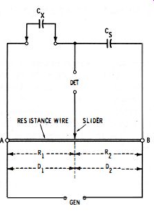
Fig. 3-1. Basic …
Neither the total resistance (R1 + R2 ) of the slide wire nor the individual values R1 and R2 need be known in order to make a Cx measurement. The calculation may be made in terms of distances Dl and D2 measured along the slide wire in centimeters, inches, or arbitrary linear units. Thus :
3-2
From the balance equations, it is seen that null occurs halfway between A and B when the unknown capacitance equals the standard capacitance, to the left of this center point when Cx > C., and to the right of center when Cx < Ca. To change the capacitance range, one needs only to change the value of the standard capacitance, C •.
Like the slide-wire resistance bridge, this type of capacitance bridge has the advantages of simplicity and relative economy. It requires few components and needs no capacitance or resistance calibration if equation 3-2 is used. And it is convenient for emergency measurements, as it requires only a standard capacitor, a length of resistance wire (stretched over a meter stick, yardstick, or other linear scale ), and a generator and detector-all usually available in the laboratory or shop. A disadvantage is the failure of the circuit to give a complete null (absolute zero balance ) unless the losses in the unknown capacitor equal those in the standard capacitor.
3.2 POTENTIOMETER-TYPE SLIDE-WIRE CAPACITANCE BRIDGE
A more compact version of the slide-wire capacitance bridge, like the similar version of the resistance bridge, substitutes a wire-wound potentiometer for the slide wire. Fig. 3-2 shows this arrangement.
In this circuit, the balancing potentiometer has a total resistance R3. At any setting, R3 = R1 + R2, the resistance between the contact blade and the low end, and the contact blade and the high end, respectively, of the resistance element. Resistances R1 and R2 determine the bridge ratio.
At null, the unknown capacitance (Cx) is determined from the standard capacitance (Cs) and the resistance ratio : 3-3
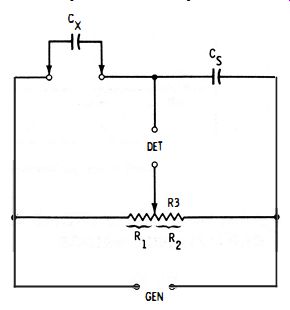
Fig. 3-2.
The potentiometer dial may be calibrated to read directly in pico-farads or microfarads by locating the null points for a number of known capacitances connected successively at Cx. It may also be calibrated with the aid of equation 3-3, in terms of measured R1 and R2 values. If the potentiometer dial already reads directly in resistance setting (as the dial of a multiturn potentiometer often does ), the unknown capacitance may be calculated with reference to that setting : where, R1 is the resistance setting indicated by the dial, R3 is the total resistance of the potentiometer.
3-4
Like the basic slide-wire bridge, the potentiometer-type circuit is simple and economical. However, it has three disadvantages : (1) because of stray capacitances in the circuit, Cx values lower than 100 pf cannot be measured accurately ; (2) unless the potentiometer has a special taper, such as logarithmic, the graduations will crowd at the ends of the dial, seriously impairing accuracy, and for that reason the capacitance range with any one standard capacitor Cs should not exceed 0. 1 to 10 times Cg, even though the potentiometer can afford a wider range; and (3) a complete null occurs only if losses in the unknown capacitor equal those in the standard capacitor.
The degrading effect of stray capacitances in the useful ranges of the bridge may be reduced somewhat by keeping the potentiometer resistance, R3, reasonably low-say, 5000 ohms. Also, the wasted ends of the potentiometer in the simple circuit may be resolved by means of extension arms (such as R1 and R3 in Fig. 3-3 ) which allow the useful 100: 1 capacitance range to be spread over the entire resistance range of the potentiometer.
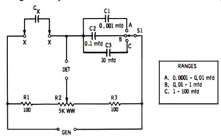
Fig. 3-3. Practical multirange potentiometer-type slide-wire capacitance bridge.
3.3 PRACTICAL POTENTIOMETER-TYPE SLIDE-WIRE CAPACITANCE BRIDGE
Fig. 3-3 shows the circuit of a practical bridge using a 5k-ohm wirewound potentiometer (R2) as the balance control. This bridge covers the range 100 pf to 100 mfd in three steps : 100 pf-0.01 mfd, 0.01-1 mfd, and 1-100 mfd. The capacitance ranges are selected by switching standard capacitors (C1, C2, C3 ). The 100-ohm non-inductive resistors R1 and R3 provide the extension arms explained in Section 3.2.
Any convenient test frequency may be employed, up to about 5 kHz. Best stability is obtained when the generator is coupled to the bridge through a shielded transformer. It is advisable also to insert a transformer between the bridge and the detector; however, this second transformer may be omitted if the first one is used, especially if the lower DET terminal is grounded.
This bridge may be calibrated by balancing it with a number of accurately known capacitors connected successively to terminals X-X, and inscribing the potentiometer dial accordingly. Only one range need be calibrated in this manner; the others will track if accurate values are used at C1, C2, and C3. Thus, the lowest range (0.0001-0.01 mfd) may be calibrated, and the A, B, and C settings of switch S1 used to multiply this basic range by 1,100, and 10,000 respectively.
The null balance is sharp if losses in the capacitor under test equal those in the standard capacitor (C1, C2, C3 ). Since high
quality capacitors customarily are used as standards, this usually means that a sharp null is obtained with low-loss test of significant losses in the capacitor under test.
3.4 THE NEED FOR POWER-FACTOR BALANCE
The preceding sections explain that a complete null is impossible with a simple slide-wire bridge unless the losses in the unknown and standard capacitors are equal . The reason for this is the complex nature of the capacitor as an impedance network (resistance and capacitance in combination, the resistance component representing the losses ). When the unknown and standard capacitors are of the same kind and magnitude, and when their equivalent impedances are the same in all respects, then a complete null may be obtained. Separate balances are required for the resistive and reactive components.
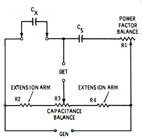
Fig. 3-4. Slide-wire capacitance bridge with power factor balance.
It is convenient to express the relation between losses (resistive component ) and capacitance (reactive component) as the power factor of the capacitor. Numerically, power factor pf = R/Z = cosine of the phase angle of the equivalent r-c network. The highest value which power factor can reach is 1 (also expressed as 100 % ). A low-loss capacitor therefore has a very low power factor. Capacitor quality may be expressed also as the quality factor Q = Xc/R = tangent of the phase angle, or as the dissipation factor D = R/Xc = cotangent of the phase angle. A low-loss capacitor has a high Q and low D. In somewhat more specific terms, the original statement may be expressed in the following way : A complete null is obtained only when the power factor, Q, or D of the unknown capacitor equals that of the standard capacitor. When these factors are unequal, as they almost always are in practice, enough resistance must be added in series (or sometimes in parallel ) with the lower-loss capacitor (usually the standard) to increase its power factor (reduce its Q) and thus make it equivalent to the higher-loss capacitor. Fig. 3-4 shows this arrangement. Here, rheostat R 1 adds this sort of compensating resistance to standard capacitor C?. In use, the bridge is balanced first for capacitance by adjusting potentiometer R3 for minimum deflection of the detector. Then, rheostat R1 is adjusted to improve the null. Additional adjustments of R1 and R3, alternately, will give complete null (dip to zero). The resistance of R1 does not enter into the calculation of unknown capacitance. Nor does the resistance of R3 enter into the calculation of power factor (see the next section ). For complete null , the resistance of R1 must be adjustable to the equivalent series resistance of the unknown capacitance, ex. A dial attached to this rheostat may be calibrated to read directly the power factor (shown either as a decimal or as a percentage ); however, this dial will read correctly only at the calibration frequency. All complete capacitance bridges are equipped with such a power, Q, or D balance.
Under some circumstances, resistive balance may be obtained also by means of a rheostat in parallel with the standard capacitor. This method works best when the dissipation factor of the unknown capacitor is higher than 1, particularly when the unknown capacitor has a significant equivalent parallel resistance (as in electrolytic capacitors ). It tends sometimes to broaden the capacitance null.
Fig. 3-5 shows how a power-factor balance rheostat is included in a universal bridge so that it may be switched in series with either the unknown or standard capacitor, whichever has the lower power factor-Le., the lesser resistance as related to capacity. (A universal bridge is a skeleton-type instrument to which unknown and standard resistors, capacitors, or inductors may be connected. ) Such a bridge is convenient for checking an unknown (Cx) against any available capacitor (Cs) whose capacitance is known, but not necessarily its power factor. When switch S1 is in position A, the power-factor rheostat (R3 ) is in series with standard capacitor Cs; when S1 is in position B, rheostat R3 is in series with unknown capacitor Cx.
3.5 CAPACITANCE COMPA RISON BRIDGE
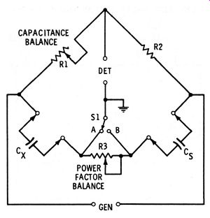
Fig. 3-5. Universal bridge with power.
The simplest and perhaps most common capacitance bridge merely substitutes capacitance arms for two of the resistance arms in the Wheatstone bridge, retains the other two resistance arms-the ratio arms-to complete the basic circuit, and adds a power-factor balance.
Because of the similarity of the two bridges, the capacitance type is sometimes familiarly called a "Wheatstone capacitance bridge," but the term capacitance comparison bridge appears most often in technical literature.
The comparison bridge overcomes many of the shortcomings of the slide-wire bridge, principally the dial crowding and lower-capacitance limit of the latter instrument. Fig. 3-6 shows the basic circuit of the comparison bridge. Here, the bridge ratio (R3/R2) is established by fixed resistor R3 and the capacitance-balance rheostat, R2.
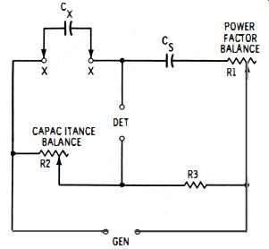
Fig. 3-6. Capacitance comparison bridge.
Cx = Cs (R3/R2 ) 3-5
The circuit of a practical multi range capacitance comparison bridge is shown in Fig. 3-7. This bridge covers the range from 10 pf to 1000 mfd in four steps : 10-1 000 pf, 1000 pf-0.1mfd, 0.1-10 mfd, and 10-1000 mfd. The similarity to the basic circuit (see Fig. 3-6 ) is easily seen, the chief difference between the two circuits being the switched values of standard capacitance C1-C3 and of ratio resistors R4 and R5 .
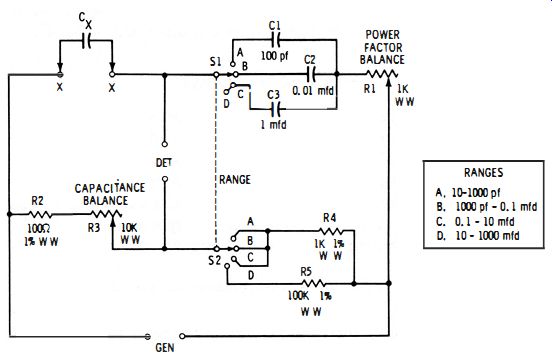
Fig. 3-7. Practical multirange capacitance comparison bridge.
The capacitance ranges are selected by switching the standard capacitance value. The same 1-mfd standard (C3 ) is used both on the 0.1-10- and 10-1000-mfd ranges by switching the ratio resistor from 1000 ohms (R4) to 100K (R5) for the higher range. Otherwise, a 100-mfd standard capacitor would be needed for the higher range, and such a high-capacitance unit is hard to obtain in accurate capacitance and low power factor. The single 1000-ohm ratio resistor (R4 ) is used on all three low ranges.
The R3 dial may be calibrated to read directly in pf and mfd either by means of equation 3-5 or by actually balancing the bridge for a number of accurately known capacitors connected successively to terminals X-X. Only one range need thus be calibrated; if C1, C2, and C3 are accurate, the other ranges will track automatically. The R1 dial may be calibrated to read directly in percent power factor on the basis of the resistance setting of R1 at complete null :
pf (%) = 0.00062 8fR1Cx
3-6
Here, f is in Hz, R 1 (the power-factor rheostat setting) in ohms, and Cx (the value of the unknown capacitance under test, read from the R3 dial ) in microfarads. However, the power factor is frequency dependent, so the power factor dial will be correct only at the calibration frequency (which, for that reason, should be the normal bridge-signal frequency-for example, 1000 Hz ).
3.6 SCHE RING BRIDGE
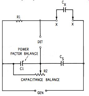
Fig. 3-8. Basic 5chering bridge.
In the Schering bridge, the resistance balance is obtained by means of a variable capacitor in parallel with one of the ratio arms (see C 1 in Fig. 3-8). This capacitor should itself have excellent power factor, so in practice it is either an air-type variable or a mica decade.
With an unknown capacitor (Cx) connected to terminals X-X, the bridge is balanced for capacitance by adjustment of rheostat R2, and separately for power factor by adjustment of capacitor C1. At null : Cx = Cs (R2/R1 ) The equivalent series resistance of the unknown capacitor is Rx = R1 (C1 /Cs)
3-7
3-8
The Schering bridge is often used for testing electrolytic and other capacitors to which a d-c voltage must be applied simultaneously with the a-c bridge signal (See section 3.8) . Practical bridges of this type have been used over a wide capacitance range (e.g., 0. 1 pf to 1000 mfd) . Ranges are changed by switching Cs and R1 together.
3.7 WAGNER GROUND
Fig. 3-9. Capacitance bridge with Wagner ground.
(A) Internal dc supply. (B) External dc supply.
Fig. 3-10. Capacitance bridge with d·c polarizing voltage.
When the bridge arms are high impedances, stray capacitances can impair the accuracy of measurement. Such capacitances from bridge arms to ground are represented by C1 and C2 in Fig. 3-9.
The Wagner ground, which is incorporated into some bridges, permits these objectionable capacitances to be balanced out. This arrangement consists simply of the auxiliary potentiometer R4 and spdt switch S1. A Wagner ground may be added to a bridge which does not already have it.
In operation, the bridge is balanced first in the normal manner; i.e., with switch S1 set to position A, rheostats R1 and R2 are adjusted for the best null that can be obtained. The switch then is thrown to position B, and potentiometer R4 adjusted for null. Next, with the switch again at A, R 1 and R2 are adjusted for deeper null; and then with S1 once more at B, R4 is adjusted for deeper null. Working back and forth in this way between the R1-R2 and R4 adjustments produces a final balance which cannot be improved by further adjustments and which frees the bridge from the effects of the stray capacitances.
3.8 BRIDGE OPERATION WITH DC POLARIZING VOLTAGE
The capacitance of an electrolytic capacitor is not the same with and without a d-c polarizing voltage. The direct application of an a-c signal to an unpolarized electrolytic capacitor, besides giving false readings, is also damaging because of polarity reversal. Moreover, the capacitance varies with the magnitude of the d-c voltage. The same is true of a capacitor having a nonlinear ceramic dielectric.
Such capacitors must be measured with their normal d-c working voltage applied simultaneously with the ac bridge signal voltage.
Fig. 3-10 shows how the a-c and d-c voltages may be applied to a typical capacitance bridge. In Fig. 3-10A, the d-c voltage is in series with the generator a-c voltage. Capacitor Cr offers a low-impedance path to the a-c signal.
Note that a capacitor (Cx, Cs ) sets up a d-c block in each branch of the bridge circuit, preventing a short circuit of the d-c supply.
However, the d-c voltage is impressed upon standard capacitor Cs, as well as upon unknown capacitor Cx, and the standard capacitors must be rated to withstand safely the maximum dc voltage which may be applied to the bridge.
Fig. 3-11. Typical Wien bridge containing capacitance and resistance components
in parallel.
In Fig. 3-10B, the d-c voltage is applied across unknown capacitor Cx. This arrangement is often used with bridges having no provision for a polarizing voltage, since an external d-c supply may easily be connected to the X-X terminals. Choke coil L (30 henrys or higher) prevents the d-c supply from short-circuiting the a-c bridge signal. A d-c milliammeter, M, may be inserted to indicate leakage current of the unknown capacitor. Capacitor Cc provides dc blocking to protect the null detector. In this arrangement, the output capacitance of the d-c power supply must be negligible with respect to the capacitance being measured; otherwise, it must be subtracted from each measured Cx value. The d-c voltage must be free from ripple, or the ripple frequency will interfere with the a-c signal and obscure the bridge balance.
3.9 WIEN BRIDGE
In the Wien bridge (Fig. 3-11) , one of the two impedance arms (C1R1 ) contains capacitance and resistance in parallel, and the other one (C2R2) contains capacitance and resistance in series. The branch containing these arms is balanced against the branch containing resistance ratio arms R3 and R4, which form a voltage divider. Resistances R3 and R4 may either be equal or in any convenient ratio.
At one frequency, null is obtained by adjusting R1 and R2. At null, the values of C1 and C2 may be determined with the aid of the following simplified Wien-bridge equations:
Thus, the two capacitance values are found in terms of frequency and resistance. This is important whenever frequency and resistance values can be known more accurately than standard-capacitor values.
If one is interested only in determining the value of C1, the capacitance of C2 need not even be known. Also, C1 and C2 both may be unknown and their values determined with equations 3-9 and 3-10 after a single bridge balance. While the capacitance calculation is somewhat involved, equations 3-9 and 3-10 may be simplified to some extent when the frequency is fixed and R3 and R4 provide a fixed ratio.
Because the Wien bridge is frequency sensitive, the generator frequency must always be stable. As long as this stability requirement is met, various frequencies may be employed, but different settings of controls R1 and R2 are required when the generator frequency is changed.
3.10 CAPACITANCE BRIDGE WITH TRANSFORMER RATIO ARMS
If the secondary winding of the bridge-generator transformer is accurately center tapped, its two halves can supply the ratio arms of the bridge, and the other two arms will consist of the unknown capacitance and standard capacitance. This arrangement is shown in Fig. 3-12.
Fig. 3-12A illustrates the basic principle. The secondary of transformer T has an equal number of turns (Nx, Ns ) on each side of the center tap; therefore, equal voltages (Ex, Es) are developed across the two halves of this winding. However, these voltages are of opposite phase, and because of this no current will flow through the detector if Cx and CII are equal-that is, if the bridge is balanced.
If Cx differs from Ca, the bridge may be balanced by varying Cs.
It may be balanced also by leaving C8 fixed and varying the number of turns (Ns) in the lower half of the secondary, as shown in Fig. 3-12B. This latter adjustment may be accomplished with a series of taps. For example, with a 100-turn lower secondary section, each 10th turn may be tapped up to the 90th turn and these taps connected to one selector switch, and each of the remaining 10 turns may be tapped and connected to a second selector switch.
(A) Basic circuit. (B) Adjustment via secondary taps. (C) Typical bridge.
Fig. 3-12. Capacitance bridge with transformer ratio arms.
The settings of the two switches then will allow Ns to be set to any value from 1 to 100 in one-turn steps, while N1: remains constant at 100. (Some commercial bridges of this type use 1000-turn secondary halves.) The value of standard capacitor Cs then may be changed to change capacitance ranges. Whichever balance method is employed, Cx/Cs = Ns/Nx, and from this relationship:

3-11
Fig. 3- 12C shows the configuration of a typical bridge employing transformer ratio arms. In this arrangement, high-efficiency toroidal core construction is employed in transformer T. The number (Ns) of lower-half secondary turns is varied by means of taps (a single switch, S1, is shown, but two or more decade switches might be included for small-step adjustment ), and this constitutes the capacitance balance. The basic capacitance range is multiplied by suitably changing the standard capacitance (C1-C5 ) by means of switch S2. Rheostat R1 in series with the standard capacitor serves as the power-factor balance.
Because a transformer may be accurately tapped, this type of bridge allows capacitance to be measured with high precision over a wide range--down to a few millionths of a picofarad. The circuit is insensitive to generator voltage fluctuations, and its ratio arms are low impedances. The transformer-type bridge is advantageous for three-terminal capacitance measurements, as is explained in Section 3. 11 .
3.11 THREE-TERMINAL CAPACITANCE MEASUREMENTS
In practical situations, capacitance never exists in two-terminal simplicity; two or more stray capacitances usually are associated with any capacitance of interest. Fig. 3-13A shows a common example of this situation. Here, capacitance Cx is not the only capacitance between capacitor terminals A and B (as might incorrectly be assumed), but is in parallel with stray capacitance C1 between terminal A and ground, and stray capacitance C2 between terminal B and ground. This three-capacitance network can result from a number of conditions : when a capacitor is enclosed in a metal can (C1 and C2 are capacitances between terminals and can) ; when a capacitor is connected to a bridge (C1 and C2 are capacitances between terminals and the metal panel of the instrument ); when an interelectrode capacitance of a vacuum tube is measured (Cx may be the grid-plate capacitance, C1 the grid-cathode capacitance, and C2 the plate-cathode capacitance ). In every instance, the main capacitance (Cx) is termed the direct capacitance.
Several techniques are available for measuring direct capacitances in the presence of stray capacitances. Fig. 3-13B shows a common one. Here, the two "stray" capacitances are returned to the ground point of the Wagner ground in the conventional capacitance bridge. (See Section 3.7 for a description of the Wagner ground.) The Wagner-ground balance then nullifies the effect of C1 and C2, and the bridge measures the direct capacitance, Cx, alone. In this way, the error which would be caused by C1 and C2 in series across Cx is avoided.
(A) Three-terminal capacitance. (B) Conventional bridge. (C) Transformer bridge.
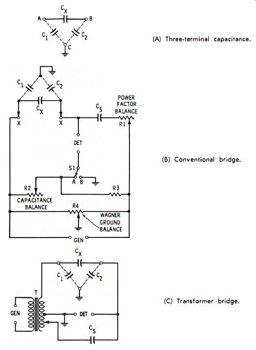
Fig. 3-13. Three-terminal capacitance measurement.
In the instance of a shielded capacitor with the shield not connected to either terminal A or B, the junction point of C1 and C2 is the shield. In a triode tube, C1 and C2 represent the interelectrode capacitances not under measurement, and the junction point of C1 and C2 is the electrode (e.g., cathode ) which is common to these two capacitances.
Fig. 3-13C shows the setup with a transformer-type capacitance bridge. Here, the C1-C2 junction is returned to the transformer center tap, which may be grounded. This places C1 across the upper transformer ratio arm, where its impedance is so high with respect to the arm that it causes no change in the secondary voltage, and places C2 across the detector, where it can have no effect on the bridge balance.
Courtesy General Radio Co.
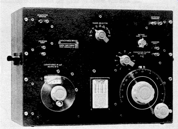
Fig. 3-15. laboratory-type capacitance bridge with provision for making substitution
measurements.
3.12 SUBSTITUTION METHOD
The difficulty of accurately measuring capacitances lower than 100 pf with some bridges, because of stray capacitances, has been mentioned in previous sections. Low values may be measured satisfactorily, however, with any bridge by using the substitution method, a process which automatically compensates for strays.
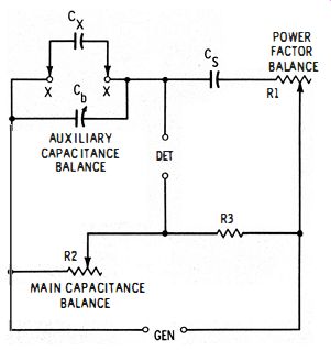
Fig. 3-14. Substitution capacitance bridge.
Fig. 3-14 shows a conventional capacitance bridge adapted to the substitution method by addition of a calibrated variable capacitor, Cb, connected to the unknown terminals, X-X. This capacitor is usually a 100- or 11 00-pf air type having a dial reading directly in picofarads. In all other respects, this bridge is identical to the one shown in Fig. 3-6.
A four-step test procedure is employed:
1. With no unknown capacitor (Cx) connected to terminals X-X, variable capacitor Cb is set to its maximum capacitance (C1), and the bridge then balanced in the regular manner by adjustment of R2 and R1. Hence, R2 is not disturbed.
2. The unknown capacitor next is connected to terminals X-X by the shortest possible leads. This adds capacitance and accordingly unbalances the bridge.
3. The bridge is rebalanced by setting variable capacitor Cb to a lower capacitance (C2 ) and readjusting power-factor balance R1.
4. Finally, the unknown capacitance is calculated from the two settings of the variable capacitor :
Cx = C1 - C2
3-12
In this way, capacitances of less than 0. 1 pf are measured with good accuracy. If long connecting leads are unavoidable, the bridge may be initially balanced in Step 1 with the leads connected to x-x and in the same position they will have when connected to the capacitor, CX' Then the capacitor is connected for the remaining steps.
A practical advantage of the substitution method is the ease with which it may be used with any capacitance bridge. Thus, a dial calibrated variable air capacitor may be connected externally to the unknown terminals of any bridge, provided that short rigid leads are used and that the four-step procedure described above is employed.
In commercial substitution bridges, the variable capacitor dial sometimes is graduated with zero at the maximum-capacitance setting of this capacitor, and with maximum capacitance at the zero-capacitance setting. The initial balance with R2 (see Step 1 above ) then becomes a zero adjustment, and after rebalance (Step 3) the dial reads Cx directly in pf, no calculation being required.
Fig. 3-15 shows a laboratory-type capacitance bridge employing the substitution method in addition to the direct method. The dial in the lower left corner of the panel operates the variable capacitor and permits the determination of C1-C2 (equation 3-12) from 0.1 to 1050 pf. An external generator and detector are required.