AMAZON multi-meters discounts AMAZON oscilloscope discounts
Most oscilloscopes, vtvm's, signal tracers, distortion analyzers, and frequency meters or counters have a comparatively high input resistance. They also have a certain amount of shunt capacitance, which will not be detrimental when used for measuring in low-impedance circuits. However, severe distortion may occur in high-impedance, high-frequency circuits, such as sync and video-amplifier circuits. Even a slight degree of loading may produce erroneous indications. With a low-capacitance probe (also known as a high-impedance or attenuation probe), the sync pulses can be followed from the take-off point to the horizontal and vertical oscillators without disturbing the synchronization of the receiver. This probe is also useful for signal-tracing and checking the signal levels through various stages of video amplifiers, because it does not contribute excessive shunt capacitance across the peaking coils to disturb the operation of the circuit. Signal levels can be observed at both the grid and the plate circuits without upsetting the circuit operation.
The low-capacitance (low-C) probe is also useful for checking the waveforms in horizontal-afc circuits. Proper waveshapes at the various test points are usually given on television schematics and in service manuals. Since a low-C probe will not load the circuit, the scope indication will be a truer representation of conditions within the circuit.
The signal observed may now be compared with the one shown in the service literature.
The grid-leak resistor in the vertical-blocking oscillator may have a value as high as 10 megohms, and the waveform at the grid will be sharply spiked. Therefore, any high-frequency content in this waveform could easily be lost if a direct scope connection were made at the grid. However, if a 10:1 low-C probe were used, the capacitance across the circuit under test would be reduced to about one-tenth the value it would be if a direct connection were made. The resultant waveform displayed on the scope will therefore be more accurate, since the circuit loading is greatly reduced. Waveform distortion may occur at the grid of some vertical oscillators, even with a 10:1 probe.
(A) Waveform without the probe. (B) Waveform with the probe.

Fig. 3-1 . Effect of a low-capacitance probe on waveform indications.
If so, a 100:1 low-C probe must be used. Fig. 3-1 shows the effect of a low-C probe on a waveform indication.
The shunt capacitance in the vertical-input circuit of an average oscilloscope is approximately 30 to 50 pf. To this we can add, on the average, another 25 to 50 pf arising from the use of the test leads.
Thus, when we place our test prod at some point within a circuit in order to observe the waveform, we are automatically shunting this point with a capacitance of 55 to 100 pf. This will have no noticeable effect in some circuits, but in others-particularly where the waveforms under observation contain .relatively high frequencies, such as square sync pulses-the additional capacitance will alter the shape of the waveform appreciably. Not only will the waveshape become distorted, but the peak amplitude of the signal will also be reduced.
Furthermore, the additional capacitance of the connecting leads, or an instrument having relatively high input capacitance, will detune resonant or tuned high-frequency circuits like the ones in television i-f stages.
The input resistance of test instruments is usually high. It may consist of the grid resistance of a tube, or the sum total resistance of a vtvm input-circuit voltage divider, plus the resistance of the isolation resistor. This resistor, as its name implies, isolates the instrument from the circuit under test. That is all well and good if we need just resistive isolation and if the signals are essentially sinusoidal . If we want to observe signals on an oscilloscope, we may use a small capacitor for isolation, instead of a resistor. That, too, will reduce the input capacitance of the instrument ; however, we do not have a known attenuation factor. Let's see what happens if a resistor or capacitor is used alone. We will soon realize that neither will do the job that both can accomplish together.
(A) Basic circuit. (B) Equivalent circuit.

Fig. 3-3. Operation of the low-capacitance probe.
Fig. 3-2. Low-capacitance probe circuit.
If, when checking waveforms with a scope, we use an isolation resistor alone in the probe, it and the distributed and input capacitance of the oscilloscope will form a low-pass filter, thereby causing integration to take place. This, of course, results in a rather large attenuation of higher frequencies and, therefore, subsequent rounding off of all sharp waveforms. On the other hand, a series capacitor alone, used to reduce the input capacitance and loading effect, would have to be a small one. The impedance of this capacitor will be quite high, however, compared with the input resistance of the oscilloscope. Therefore, this combination-the series capacitor and input resistance-will form a differentiating network (high-pass filter), resulting in attenuation of the lower frequencies. If we now combine a series resistor and a capacitor of the proper value to get not only low shunt capacitance, but also frequency compensation and a known attenuation ratio, we will have accomplished what we set out to do. Fig. 3-2 illustrates the basic circuit for such a probe in which a low-value, semivariable capacitor and a shunt resistor are encased in a special housing. The reduction in shunt capacitance takes place because the added capacitor (approximately 5-15 pf) is actually placed in series with the 80 to 100 pf from the connecting cable and the vertical-amplifier input circuit. This added capacitance reduces the effective input capacitance to a little less than the 5- to 15-pf--certainly a marked improvement over the 80 pf or so present before the probe was added.
There is, however, one disadvantage to this arrangement: the voltage actually reaching the vertical amplifier of the scope is reduced in the same proportion as the input capacitance. Thus, if the total input capacitance is decreased to one-tenth, so is the signal voltage reaching the scope. In television service work, the low-C probe is usually used for observing waveforms in circuits which have sufficient voltage to offset this loss, such as the video-amplifier, sweep, and sync stages.
Let us look at a simplified diagram (Fig. 3-3) in order to understand the operation of a low-capacitance probe. Since the probe is always used with a shielded lead, the capacitance of the shielded cable (C(, in Fig. 3-3A) and the input capacitance of the instrument are added together. This total capacitance (which we will call Cr) is shunted by the input resistance (Rr) of the instrument. The resistor in the probe is denoted Rp and the probe capacitance Cp.
The signal under test is applied between terminals A and B. The equivalent circuit in Fig. 3-3B shows we now have a voltage divider consisting of two resistors shunted by two capacitors.
Low frequencies divide across R1 and Rr in direct proportion to their resistance and the high frequencies divide across Cp and Cr in inverse proportion to their capacitance, or in direct proportion to their capacitive reactance. The voltage division is constant from direct current up into the r-f range. The attenuation factor is very easily calculated, as we will soon see. Essentially, the probe increases the input impedance of the test instrument and, at the same time, attenuates the input signal . The attenuation factor can generally be compensated for by simply adjusting the vertical-gain control of an oscilloscope for greater deflection, provided the signal under test is of sufficient amplitude . We have, however, gained the advantage of reducing or eliminating waveshape distortion, which would normally occur if there were no low-C probe.
In order for the probe to be properly compensated for at all frequencies, the following relationship must hold true:
Cp Rp
= Cr Rr where,
Cp is the probe capacitance,
Rp is the probe resistance,
Cr is the input capacitance (cable plus oscilloscope),
Rr is the input resistance of the oscilloscope.
The amount of attenuation experienced from using the low-C probe is given by the following formula:
A = Rp + RI RI A
= XCI' + XCI
= C1, + CI XCI CI,
Now suppose we have an oscilloscope with an input resistance of 500,000 ohms and an input capacitance of 25 pf. Using a two-foot coaxial cable with a capacitance of 10 pf per foot between the probe and the oscilloscope will add 20 more pf. Therefore, the effective input capacitance of the scope will now be 45 pf. Let us see what the values of R1' and C1, would have to be to provide an attenuation factor of 10: 1.
Since
Therefore,
R1 = SOaK C1 = 45 pf R1 ,
= 500,000 (10 - 1)
= 500,000 x 9
= 4.5 megohms
We need a probe resistor of 4.5 megohms for an attenuation factor of 10: 1. Now, what will Cp have to be?
Since
Therefore,
A = Cp + Cr Cp , CI Cl,
= (A - 1)
_ 45 pf C - (l O - l )
_ 45 pf
- 9-
= 5 pf
Thus, we need 5 pf for the probe capacitor. What must we do to make this probe practical to construct? A 4.5-megohm resistor is quite easy to obtain. However, as far as the capacitor is concerned, there are several problems. First of all, the input capacitance of the oscilloscope may vary by 20 percent or more from the manufacturer's specifications. Moreover, the cable capacitance may also vary by the same percentage. We also have to take into account a little distributed capacitance here and there. So, from a practical point of view, a small adjustable ceramic or mica trimmer capacitor between 3 to 30 pf can be used. Its exact value is not important since it will be adjusted anyway. However, its lowest value must always be lower than the calculated probe capacitance ; and its adjustment range is expected to compensate for other distributed capacitances in the circuit.
Not only does the low-C probe raise the input capacitance and reduce the input signal by the same attenuation factor, but it also attenuates any DC component in the circuit under test. In doing so, it reduces the DC voltage stress across the series blocking capacitor in the input circuit of AC oscilloscopes (some of which have either AC or DC inputs). In a DC scope or at the DC input setting on an AC/ DC oscilloscope, this blocking capacitor is not in the circuit, of course.
Frequency compensation of a low-C probe is best accomplished with a square-wave generator. The trimmer in the probe is adjusted for best square-wave reproduction at 20 and 20,000 hz. Several adjustments should be made by alternately switching back and forth between 20 and 20,000 hz. Usually, a satisfactory compromise adjustment can be made after a few tries. If a square-wave generator is not available, an audio sine-wave generator will do. Adjust the probe trimmer for a sine wave of equal amplitude (or a compromise) at 20 and 20,000 hz. Repeat the adjustment several times as before.
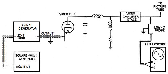
Fig. 3-4. Test setup for checking the response of a video amplifier with a
low-C probe.
A properly operating television receiver can also be used in adjusting the low-C probe. Apply the probe at the grid or cathode of the picture tube (depending on which elements are fed from the video-output stages) and observe the composite video signal on the oscilloscope. Then adjust the capacitor in the probe until the equalizing and vertical-sync pulses have the same peak amplitude and observe the horizontal pulses for proper shape (set the oscilloscope sweep rate at 15,750 hz). The trimmer capacitor in the probe can again be slightly adjusted, if necessary, so the horizontal-sync pulses will have the least rounding and tilt.

Fig. 3-5. A low-C probe with peaking coil added to help compensate for insufficient
vertical amplifier bandwidth in some oscilloscopes.
In many instances the frequency response of a particular oscilloscope is so narrow that the higher frequencies are attenuated. Thus, when a composite video signal is viewed (the higher frequencies in this instance), the horizontal-sync (15,750 hz) and equalizing pulses (31,500 hz) are not amplified as greatly as the low-frequency vertical pulses (60 hz). Never forget that the frequency characteristic of the scope presentation can be only as good as the response of the scope before the probe was added.
A low-C probe should not be used when the full sensitivity rather than the wide-band response of an oscilloscope is required-for example, in tracing and locating hum. Instead, a direct probe made of ordinary shielded cable is preferred.
(A) Without peaking coil. (B) With proper peaking-coil inductance. (C) Inductance of peaking coil too low. (D) Inductance of peaking coil too high.

Fig. 3-6. Effect of peaking coil inductance on the response curve.
Fig. 3-4 shows the proper way to check the response of a video amplifier with a low-C probe. If we want to observe the video signal at the picture tube, it is advisable to disconnect the picture tube so the circuit will not be disturbed by the slight capacitance added by the probe. By unplugging the picture-tube socket, we have actually substituted the input capacitance of the probe for that of the picture tube.
Insufficient vertical-amplifier bandwidth in oscilloscopes with no peaking coils can be improved by adding a small, damped peaking coil in the probe, as shown in Fig. 3-5 . The value of the coil will fall somewhere between 150 and 300 microhenrys--depending on the distributed capacitance in the probe, cable, and scope. Several values of inductance should be on hand; the proper one is determined experimentally. Damping resistor R1 in Fig. 3-5 reduces the Q of the coil to provide a broader peak and thus an essentially flat overall frequency response. Its exact value can be anywhere from 5000 to 10,000 ohms.
(A) Short DC blocking capacitor (if used) (B) Place potentiometer in series with scope and connect signal source to scope. vertical-input lead. (C) Measure resistance across potentiometer.
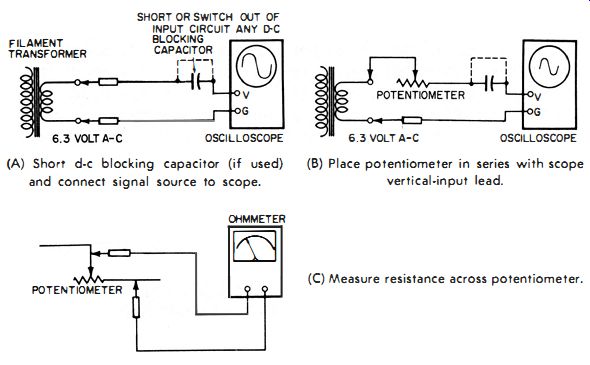
Fig. 3-7. Measuring the input resistance of an oscilloscope.
In order to determine the best value for L, apply the output from a video sweep generator to the probe, and observe the un-demodulated response curve on the oscilloscope. Fig. 3-6 shows the effect of the peaking coil on the response curve. Try several values of L for best response, and adjust the trimmer capacitor in the probe for the flat test output. Use the smallest possible inductance consistent with a good response curve . Of course, the output of the video sweep generator must be flat. (This can be quickly checked with a demodulator probe.) It is therefore desirable to use a cable with the lowest possible shunt capacitance, because the cable itself adds a substantial amount. at the picture tube, it is advisable to disconnect the picture tube so the circuit will not be disturbed by the slight capacitance added by the probe. By unplugging the picture-tube socket, we have actually substituted the input capacitance of the probe for that of the picture tube.
Insufficient vertical-amplifier bandwidth in oscilloscopes with no peaking coils can be improved by adding a small, damped peaking coil in the probe, as shown in Fig. 3-5. The value of the coil will fall somewhere between 150 and 300 microhenrys-depending on the distributed capacitance in the probe, cable, and scope. Several values of inductance should be on hand; the proper one is determined experimentally. Damping resistor R:! in Fig. 3-5 reduces the Q of the coil to provide a broader peak and thus an essentially flat overall frequency response. Its exact value can be anywhere from 5000 to 10,000 ohms.
(A) Short DC blocking capacitor (if used) (B) Place potentiometer in series with scope and connect signal source to scope. vertical-input lead. (C) Measure resistance across potentiometer.

Fig. 3-7. Measuring the input resistance of an oscilloscope.
In order to determine the best value for L, apply the output from a video sweep generator to the probe, and observe the un-demodulated response curve on the oscilloscope. Fig. 3-6 shows the effect of the peaking coil on the response curve. Try several values of L for best response, and adjust the trimmer capacitor in the probe for the flat test output. Use the smallest possible inductance consistent with a good response curve . Of course, the output of the video sweep generator must be flat. (This can be quickly checked with a demodulator probe.) It is therefore desirable to use a cable with the lowest possible shunt capacitance, because the cable itself adds a substantial amount.
The lower the instrument and cable capacitances, the smaller the compensating capacitor can be, with a consequent reduction in the shunting capacitance of the probe.
A set of five low-capacitance probes is made by Tektronix, Inc. The attenuation ratios which are now available are 5:1, 10:1, 20:1, 50:1, and 100:1.
The input resistance of an oscilloscope can be easily measured in the following manner. First be sure any DC blocking capacitor in the input circuit (Fig. 3-7 A) is either shorted or switched out of the circuit. Then connect a low-voltage AC signal (such as the 6.3 volts from a filament transformer) to the vertical-input terminals of the oscilloscope, and adjust the vertical-gain control to obtain nearly full-screen deflection or an even number of divisions. Now disconnect one lead and insert a 3- to 5-meg potentiometer in series with the lead, as shown in Fig. 3-7B. Without disturbing the scope setting, adjust the pot until the signal deflects exactly half the number of divisions it did originally. Remove the pot and measure with an ohmmeter that portion of the resistance that was inserted in the circuit (Fig. 3-7C). The value measured will equal the input resistance of the scope.
(A) Apply a 300 khz sine wave to vertical input of oscilloscope. (el Measure capacitance with a bridge. (B) Place an adjustable capacitor in series with scope vertical-input lead.
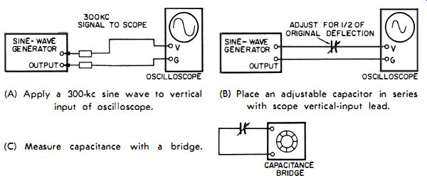
Fig. 3-8. Measuring the input capacitance of an oscilloscope.
In order to measure the input capacitance of the oscilloscope, we proceed as follows: First, set the scope vertical attenuation to the position at which we wish to measure the capacitance. Apply a 300-khz AC signal (Fig. 3-8A) and note the deflection. Now disconnect one scope lead and add a small adjustable capacitor (around 100 pf or so) in series with the lead, as shown in Fig. 3-8B. Try various values, or a trimmer in parallel with a fixed capacitor. The value giving exactly one-half the deflection, when the signal was directly connected to the input circuit, is equal to the input capacitance of the scope. Determine the amount of capacitance with a capacitance bridge (Fig. 3-8C) . Be sure the level of the signal stays constant during this test.
Probe attenuation can be checked by applying a 1000-hz sine wave to the vertical-input terminals and adjusting the scope deflection to a convenient number of divisions as close to full-scale deflection as possible. Now connect the probe to the scope terminals and apply the same 1000-hz signal voltage to the probe. This time the deflection will cover a much smaller number of divisions. Divide this number into the one previously obtained. The result is the probe attenuation factor. For example, if there were 40 divisions of vertical deflection without the probe and now, with the probe, only four divisions, the probe attenuates 40 divided by 4, or a factor of 10. Frequency compensation must be made, of course, as outlined before.

Fig. 3-9. Low-capacitance probe with micro- switch added to reduce sign.1
bounce.
Fig. 3-10. High-impedance, un-compensated gain-control used in some oscilloscopes.
When a direct or low-capacitance probe is connected to an oscilloscope, but the probe tip is not connected to anything, a stray field signal will appear on the screen if the gain of the oscilloscope is turned up high. This is called pickup and appears because the probe tip presents a very high impedance. This type of interference will disappear as soon as the probe is connected to the circuit under observation.
When a low-capacitance probe is applied at the plate or screen of a tube or at any other point where a DC voltage is present in addition to the AC signal under observation, a bounce trace will be seen.
When the probe tip is connected to the test point, the input blocking capacitor of the oscilloscope charges to the DC voltage present.
This charging action takes place through the probe and the vertical input of the scope attenuator circuit. Oscilloscopes designed to have good low-frequency response usually have a large value blocking capacitor; this may be as much as 1 mfd. Charging such a large capacitor through a high resistance produces a long charging surge, which, in turn, could produce a long and disturbing bounce in the signal.
A slight modification of the low-capacitance probe can avoid this problem. Fig. 3-9 shows a normally closed switch added to the probe so that the input blocking capacitor, which is now in the probe, be-comes charged immediately when a DC potential such as the plate of a vacuum tube is applied across it. The switch (a small microswitch inserted in the tip of the probe) can now be opened, and the signal will appear without a bounce. With a little ingenuity the microswitch can be installed in the probe so that any pressure which is produced when the probe tip is connected to the test point will open the switch automatically, eliminating the necessity for performing this function manually.
Shorting the blocking capacitor to ground eliminates bounce, but it also connects a very large capacitor in shunt with the circuit under observation. This could have a serious detuning effect and might even cause some circuits such as blocking oscillator circuits to cease functioning. However, when the switch is opened, the circuit will resume normal operation, which could result in the change of some DC levels at the test point. This will produce some bounce which, in this case, cannot be avoided.
To review briefly, there are three distinct advantages of a low capacitance probe.
1. The input impedance is kept high.
2. The input impedance is known and can therefore be reckoned with because it does not depend on the leads or their proximity to ground.
3. Pickup of extraneous signal is reduced to a minimum because a shielded lead is used.
(A) Grid resistor connected to ground. (B) Grid resistor connected to cathode.

Fig. 3-11. Basic cathode·follower circuit.
CATHODE-FOLLOWER PROBES
Cathode-follower probes provide another means of offsetting the loading effect of an instrument on high-impedance circuits. A cathode follower is a high-impedance input/low-impedance output device which exhibits excellent frequency response.
In order for high-frequency waveforms in high-impedance circuits to be measured or observed with any degree of success, the input impedance of that measuring device must be considerably higher than that of the circuit point being measured.
All measuring instruments affect, even if only to a small degree, the circuit to which they are connected. This disturbance becomes more noticeable in high-impedance circuits. The ideal measuring device would require absolutely no energy from the circuit under test. In order to approach this ideal condition, we endeavor to make the input impedance of the instrument as high as possible-which, of course, would require the shunting resistance to be high and the shunt capacitance quite low.
One of the problems in measuring voltages with a high-impedance voltmeter or oscilloscope in high-impedance audio and video circuits is the effect of test-lead capacitance. Shielded test leads are usually necessary to prevent hum pickup, but their shunt capacitance may seriously load the circuit under test-even as high as 100 pf or more.
At 15 khz this represents a reactive loading of about 100,000 ohms-a very appreciable amount, even across a one-half megohm circuit.
An average oscilloscope, together with its shielded cable, offers a circuit load of about 2 megohms shunted by around 125 pf. However, for proper compensation we must take into account the position of the vertical-gain control.
Some of the more inexpensive oscilloscopes have uncompensated vertical-input circuits like the one in Fig. 3-10, in which the input capacitance varies with each setting of the vertical-gain control . Thus, it is not practical to use a low-C probe at any but the one setting for which it has been calibrated. On the other hand, a cathode-follower type low-C probe overcomes this problem and, in addition to its other advantages, is the only practical probe that can be used with an oscilloscope having an uncompensated vertical-gain control . A cathode follower resembles an RC-coupled amplifier, except that the output is taken from the cathode instead of the plate circuit. The basic circuit of a cathode follower is shown in Fig. 3-11 A. Notice that the grid resistor (Rg) goes directly to ground.
When a signal is applied, the plate current changes in step with the control-grid to cathode voltage. Since the plate and cathode currents are the same, the cathode current also changes when the plate current changes, reproducing the input signal across the unbypassed cathode resistor (Rk). The output signal , which is taken from across Rk, has the same phase as the applied signal.
Since the cathode return is also part of the grid-cathode circuit, the output voltage across the unbypassed resistor (Rk) is opposed by part of the input voltage. As a result, negative feedback and degeneration are introduced. The voltage developed across R1; can never be equal to (or greater than) the applied voltage. Thus, the cathode follower has a gain of less than unity. We have a high input impedance at the input of the circuit, but a low impedance at the output. No voltage gain is derived, therefore, although the circuit does have a large power gain.
Fig. 3-11 B shows a slight modification of the cathode-follower circuit. The input resistor (R ) is now returned to the cathode . This connection makes it possible for a higher value of cathode resistor to be used and, consequently, a signal of greater amplitude to be applied.
To understand how a cathode follower works, assume we have an input signal of one volt applied between the grid and ground (the input terminals of the probe). The output voltage is taken across cathode resistor R1;. Because grid resistor Rj! is connected to the cathode and not to ground, it is in series with the cathode resistor. Consequently, we have a current amplifier with a voltage gain of somewhat less than 1. For ease of understanding and for the sake of illustration, let us assume the voltage gain is 0.9. Therefore, with an input signal of 1 volt, we will get an output signal of 0.9 volt.
If we apply a 1-volt signal of such polarity that the grid is positive, the cathode current through R1; will immediately increase, making the cathode more positive with respect to ground. Thus, as the grid goes positive, so does the cathode . The cathode voltage changes in phase with the input voltage. The voltage across cathode resistor R1; will approach the input voltage. As we said before, for ease of understanding we shall assume a gain of 0.9 for the circuit. Thus, only 0. 1 volt remains across the grid resistor, which therefore looks 10 times as large as it actually is. For example, with a 10-megohm grid resistor, the input resistance of the probe will be 10 times as much, or 100 megohms.
The input resistance of circuit B is equal to Rg -;- I - A, where A is the gain of the circuit. H the gain is 0.95 and Rg is still 10 megohms, Rin will be 200 megohms.
With good design, the gain of a cathode follower can be made as high as 0.98--which, of course, would greatly increase the input resistance. Theoretically, if the gain could be made exactly I-in other words, if the output signal (the one across Rk) would be exactly equal to the input signal-the input resistance would be infinite.
In the circuit in Fig. 3-11 A, the input resistance is equal to the value of the grid resistor. Because of the large amount of inverse feedback, the output impedance is only a few hundred ohms. So, we can feed our output signal to an oscilloscope or vtvm through a shielded lead, without running into pickup problems or undue attenuation of high-frequency signals.
(A) The probe. (B) Probe circuit. Courtesy Jackson Electrical Instrument Co.
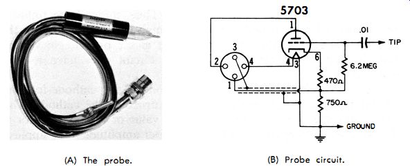
Fig. 3-12. Jackson LC·2-1 P cathode follower probe.
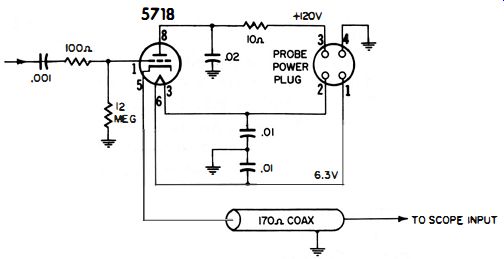
Fig. 3-13. Schematic of the Tektronix P1 70 CF cathode follower probe.
A cathode-follower probe is also suitable for use with an AC vtvm.
However, the gain of the probe, being somewhat less than 1, must be taken into account when voltage readings are made.
Another very favorable advantage of a cathode follower is that the capacitance between the grid and cathode circuits is also decreased by a factor of 1 - A. Thus, for a gain of 0.9 we are left with only one tenth the grid-to-cathode capacitance. The only other capacitance left is grid-to-plate, which accounts for about half the total input capacitance.
Sometimes it is advisable to use a cathode-follower probe ahead of a demodulator probe if circuit impedances are so high that the demodulator probe alone would present greater loading than can be tolerated. The cathode-follower probe can thus "pick-off" the signal and convert it to a low-impedance level without too much loss-at which time the demodulator probe takes over.
Now, for some practical circuits. Some oscilloscope and vtvm manufacturers have provided for a cathode-follower type of low-C probe, in which the required supply voltages are furnished by the test equipment being used. The Jackson Model LC 2- lP probe in Fig. 3-12, is designed for an oscilloscope equipped with a connector to provide the necessary filament and plate voltages. This connector also carries the cathode-follower output signal to the vertical-input circuit of the oscilloscope.
(A) Attenuator 1. (B) Attenuator 2. (c) Attenuator 3.
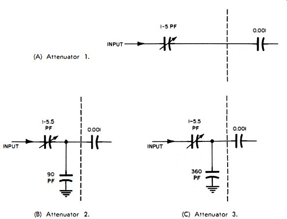
Fig. 3-14. Attenuations used with the cathode-follower probe in Fig. 3-13.
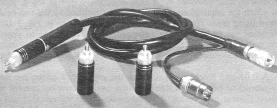
Fig. 3-15. The P 170·CF cathode follower probe and the various attenuators.
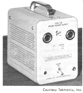
Fig. 3-16. A probe power supply.
A 0.01 -mfd blocking capacitor in the grid circuit allows AC measurements to be made in circuits where both alternating current and direct current are present. The maximum signal voltage that can be applied to this probe is 25 volts peak-to-peak, and the maximum DC level at which measurements can be made is 500 volts. The input impedance of the probe is 6.2 megohms, shunted by 8 pf. A 5703 subminiature tube is used in the cathode-follower circuit, and the probe has an attenuation ratio of 2 to I-lower than the ratios of the r-c type low-C probes discussed previously.
Another cathode-follower probe is the Tektronix P 170-CF shown schematically in Fig. 3-13 . The three attenuator circuits used with it are shown in Fig. 3-14. This probe, when used without attenuators, also has an attenuation factor of 2-to- l. It is designed for a maximum signal input of no more than ±2 volts peak for undistorted output.
Available are variable attenuator heads that screw onto the head of the probe (Fig. 3-15 ) and are adjustable by means of a screwdriver adjustment in the nose.
A maximum signal of ±6 volts may be applied at a minimum setting of the first attenuator (Fig. 3- 1 4A). For an attenuation ratio of 20 or over, the input signal may be increased to ±20 volts with the second attenuators (Fig. 3-14B). If we use the third attenuator (Fig. 3- 14C), which gives a minimum attenuation of 200, a maximum input signal of ±200 volts may be applied.
This probe is used with a Type 517 oscilloscope, which has provisions for supplying the plate and filament voltages required for proper operation of the 5718 tube in the probe.
Note that there is no cathode resistor in the probe . The cathode follower depends on the termination of the coaxial cable to complete its cathode circuit to ground. When the probe is used with the Type 517 oscilloscope, the cathode resistor of the tube is the 170-ohm input termination of the preamplifier grid line in the scope. With any other oscilloscope, however, a suitable 170-ohm termination resistor must be connected across the vertical-input terminals of the scope. For proper matching, the output signal from the cathode follower is fed through the coaxial cable, the characteristic impedance of which is also 170 ohms. If the instrument has no plate and filament voltages, a source of low-ripple 120-volt B+ and 6.3-volt filament voltage (150 milliampere; preferably direct current) must be made available. A power supply suitable for operating two of these probes is shown in Fig. 3-16.
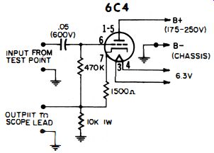
Fig. 3-17. An easily constructed cathode follower probe.
A mathematical analysis would show that a cathode follower with a capacitive load in a cathode circuit exhibits a negative-resistance component (conductance) at certain frequencies. For example, the probe circuit in Fig. 3-13 exhibits conductance between approximately 2.5 to 12 megacycles, its greatest value being somewhere between 7 and 8 megacycles. Therefore, in an inductive or tuned circuit that resonates between 2.5 and 12 megacycles, we may experience an apparent increase in the Q of the circuit. If the circuit losses are sufficiently low, the application of the probe may cause oscillations, similar to the way a Colpitts oscillator operates. Such difficulties can generally be overcome by inserting an isolation resistor of several thousand ohms at the probe tip.
Always remember, when using a cathode-follower probe, that the output-signal level will contain a DC component of several volts.
Therefore, if there is no DC blocking capacitor, one must be inserted in the input circuit of the oscilloscope. When an AC/ DC scope is employed, the switch should be in the AC position.
If no cathode-follower probe is at hand, one can be very easily constructed for checking equipment when a filament and plate voltage source is readily available. This might happen while we are servicing a television receiver and want to make observations on an oscilloscope, but have neither a low-C nor a cathode-follower probe handy.
Fig. 3-17 shows the circuit of a cathode-follower probe that can be easily assembled because it contains only a few parts.
The filament and plate voltages for this probe are taken from the receiver with which it is used. Signals up to 75 volts peak-to-peak can be applied to this cathode follower. Higher ones should be attenuated before they are applied to the probe, or else they can be directly applied to the vertical-input terminals of the oscilloscope.

Fig. 3-18. Nuvistor-transistor high impedance probe.
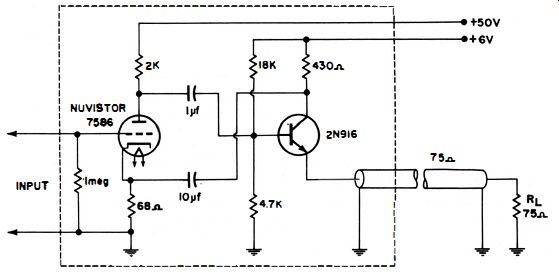
Fig. 3-19. Schematic of unity-gain, nuvistor-transistor high-impedance probe.
Fig. 3-18 shows a photograph of a unity-gain, low-capacitance probe which combines the advantages of the high input impedance of a nuvistor vacuum tube with the low output impedance of the transistor emitter-follower circuit. The probe has a nominal gain of unity at 50 megacycles and a minimum input impedance of one megohm shunted by approximately 50 picofarads. It has an output of one-half volt peak-to-peak into a 50-ohm load at frequencies up to 100 megacycles. When operating from a 50-ohm source, the frequency range extends from 10 hz to 200 megacycles. The equivalent input noise is less than 40 microvolts at a 50-megacycle bandwidth with a 10-kilohm input terminator and is typically 130 microvolts at full bandwidth. This particular probe requires a power source of 25 volts DC at 30 ma and 6.3 volts AC at 0.15 amp.
A representative circuit of a nuvistor-transistor probe is shown in Fig. 3-19. Input is to the grid of the nuvistor whose plate is coupled through a 1-mfd capacitor to the transistor base. To achieve low output impedance the transistor is connected in an emitter-follower configuration. To maintain high-gain stability, negative feedback is obtained by adding the 10-mfd capacitor from the collector of the transistor to the cathode of the nuvistor, resulting in overall unity gain. The maximum input level is about 0.2 volts.