AMAZON multi-meters discounts AMAZON oscilloscope discounts
To those who know anything about electronics, the question "What is a capacitor?" may sound rather pointless.
They may know what capacitors look like, having used them in the repair of equipment, in experimenting, or in the construction of some equipment. But do they really know the basic principles of capacitors--their characteristics, performance, and construction?
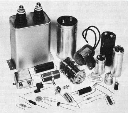
Fig. 1-1. Common types of capacitors.
There are literally dozens of different kinds of capacitors, varying in size, shape, and value. Fig. 1-1 shows a few of the more common types. Each has something in common with the others, and yet each is designed for specific applications where it excels the others in performance.
DEFINITION
In order to properly explain why there are so many kinds of capacitors, and why one type will do a certain job better than another, we have to start by learning more about what a capacitor really is. Let's begin with the simplest definition possible: a capacitor is an electronic device capable of temporarily storing electrical energy. It would be quite possible to confuse this definition with the one for a battery. There is, however, an essential difference between the two. A battery stores electrical energy, releasing it by chemical action, whereas a capacitor stores the actual electrons themselves.
In other words, a battery is essentially a chemical device, and a capacitor is an electronic device.
Although a capacitor is not a battery, it can exhibit some of the characteristics of a battery. In addition, capacitors are capable of acting like resistors, rectifiers, or inductors.
To add to the confusion, they can exhibit these characteristics all at the same time and still perform the functions of a capacitor.
HISTORY
For the moment, however, let's not be concerned about these other characteristics. Instead, let's concentrate on a simple explanation for this device, and the best place to start is at the beginning--back when capacitors were first discovered. It all happened in the year 1746. The place was Leyden, Holland, where a physicist by the name of Pieter van Musschenbrock was performing some experiments in an attempt to "electrify" water. He had a number of bulky batteries, a few glass jars, and some thin copper foil. You must bear in mind that this all took place at the very dawn of the electrical age, when the scientists of the day were willing to try anything--no matter how ridiculous it may seem to us today. At any rate, van Musschenbrock's experiment consisted of lining a thin glass jar inside and out with copper foil, filling the jar with water, and then dropping it into a larger jar which was also filled with water. When he attached the leads from the batteries, nothing happened.
Naturally, he assumed his attempt to "electrify" water was unsuccessful, so he emptied the jars and disconnected the batteries. In so doing, he accidentally touched the leads from the two copper foils, and received a distinct and unpleasant shock. This came as a surprise to him, since the batteries were no longer in the circuit. Well, you and I know that van Musschenbrock had accidentally produced a capacitor.
It is interesting to note that his original construction is almost identical to the present-day laboratory standard.
His discovery is called the Leyden jar, in honor of its place of discovery. (It's unfortunate Herr van Musschenbrock's name wasn't a little shorter and easier to spell, because he gets very little glory for what he did.)
INSIDE COPPER FOIL; GLASS JAR; OUTSIDE COPPER FOIL; BATTERY
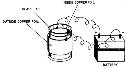
Fig. 1-2. Basic Leyden jar capacitor.
BASIC CONSTRUCTION
Fig. 1-2 shows the basic configuration of the Leyden jar. Notice that one copper foil is connected to the positive terminal of the battery, and the other to the negative terminal. The two foils are unable to touch each other because they are separated by the glass jar. Here we have the three essential parts of any capacitor: two conductors (the copper foils) and an insulator (the glass jar). Each of these three parts has a name: the positive conductor is called the anode plate, the negative conductor is the cathode plate, and the insulator is called the dielectric. It makes no difference whether the parts are cylindrical (as in the Leyden jar) or flat; the names remain the same--anode, cathode, and dielectric.
Suppose we take the cylindrical Leyden jar and flatten it. The essential ingredients of the capacitor remain-two conductors separated by an insulator (Fig. 1-3). Now this insulator (dielectric) can be glass, or any of a dozen other insulating materials such as mica, plastic, paper, ceramic even air or a vacuum. The essential thing to bear in mind is that the conductors (plates) must be electrically insulated from each other. If they are allowed to touch, the ability of the device to store electrons will be destroyed.
INSULATOR (DIELECTRIC); ANODE CONDUCTOR (PLATE); CATHODE CONDUCTOR (PLATE)
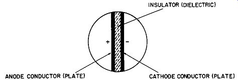
Fig. 1-3. Basic parts of a capacitor.
BASIC THEORY
Since there is no direct connection between the two plates, no current should flow--even though each is connected to a battery terminal. There is, however, a tendency for the electrons to want to pass from the negative to the positive plate through the dielectric. In other words, a potential exists across the two conductors, and electrons tend to accumulate on the surface of the negative plate (see Fig. 1-4A). Even after we disconnect the battery, they will stay there (Fig. 1-4B). However, if the two leads are permitted to touch, the accumulated electrons on the negative plate will have a way to reach the positive plate, which is lacking in electrons.
Since the electron movement is instantaneous, a spark will be produced (Fig. 1-4C).
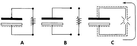
Fig. 1-4. Electron storage on the surface of the negative plate.
The number of electrons stored on the surface of the negative plate depends on its area and on the total force applied to put them there. Suffice it to say that the electrons are there, and that obviously our capacitor is capable of storing them for a short period (witness the spark). It therefore follows that a capacitor has the ability to store a given amount of electrons. The term capacitance is used in referring to the amount of electrical energy a capacitor can store.
MEASUREMENT UNITS
This brings up the question "How does one evaluate or measure capacitance?" Michael Faraday developed the method we use today. In fact, the basic unit of capacitance--the farad--is named after him. A capacitor which requires one ampere of current to raise the potential across the plates by one volt in one second is said to have a capacitance of one farad.
Now, one ampere of current is a rather large amount and, as one might suspect, a one-farad capacitor would be enormous indeed. As a matter of fact, such a large capacitor is impractical for use in everyday circuitry (although some equipment requires the use of even larger units). Much smaller units, with values expressed in microfarads and micromicrofarads, are most commonly used. A microfarad is equal to one millionth of a farad, and a micro-microfarad, to one-millionth of a microfarad. Or:
1 microfarad (mfd, mf, f.lf) = 1 00
~
000 farad , ,
VARIATIONS IN CONSTRUCTION
Let us now examine two capacitors, one a 50-mfd unit rated at 5 volts, and the other a 50-mfd value with a rating of 450 volts. What's the difference between them, and why? In order to understand the difference, we have only to consider the basic capacitance formula. The number of electrons a capacitor can store is a function of the plate area. In addition, we have two other factors to consider the kind of dielectric used, and the distance between the two plates (thickness of the dielectric).
The formula we will use is:
KA C = 0.2235 cC (N-1)
where,
C is the capacitance in micromicrofarads (mmf), K is the dielectric constant of the insulator, A is the area of one plate in square inches, d is the distance between the plates in inches, N is the number of plates.
Dielectric constants for the more common materials are listed in Table 1-1.
Using the capacitance formula, we find that two one square-inch plates, separated by Kraft paper (K = 4.0) .001 inch thick, will have a capacitance of approximately 90 mmf. It should be noted that the thinner the dielectric, the smaller the capacitor can be physically and still retain its rated capacity. In other words, capacitance increases as the distance between the plates decreases; thus, the same amount of capacitance can be achieved with smaller plates.
There is, however, another factor to be considered, and that is the applied voltage. If it becomes too great, a flashover or breakdown will occur.
-----------------------
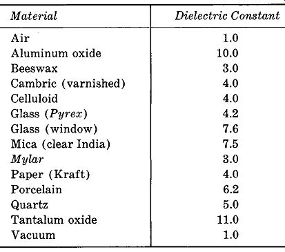
Table 1-1 Approximate dielectric constants of common capacitor materials.
Material | Dielectric Constant
Air 1.0
Aluminum oxide 10.0
Beeswax 3.0
Cambric (varnished) 4.0 Celluloid 4.0 Glass (Pyrex) 4.2 Glass (window) 7.6 Mica ( clear India) 7.5 Mylar 3.0 Paper (Kraft) 4.0 Porcelain 6.2 Quartz 5.0 Tantalum oxide 11.0 Vacuum 1.0
-------------------
A potential of 5 volts is less likely to produce enough stress to cause a breakdown, compared with a potential of 450 volts. This, then, is the principal difference between capacitors with the same value but different voltage ratings.
As you can see from the previous paragraphs, a capacitor is subject to several compromises in design. In order to raise capacitance, we can do any of three things-move the plates closer together, increase the plate area, or use a better dielectric ( one with a higher K). On the other hand, to avoid voltage breakdown we may have to space the plates farther apart (which makes the capacitor larger), or use a different and perhaps more expensive dielectric.
CAPACITOR SAFETY
Before we close this section, let's take a moment to dwell on the potential danger involved in handling capacitors.
One can receive a nasty shock, or even a fatal one, by failing to observe certain elementary safety precautions.
Capacitors can be lethal weapons--don't ever forget that.
A current as small as 5 milliamperes can be lethal under certain conditions. Before handling a capacitor be certain it has been properly discharged. This does not mean using a screwdriver or touching the leads together. Capacitors should be discharged only through an appropriate resistor.
A very rapid discharge through a short conductor can ruin an otherwise valuable component. Also make certain the discharging resistor is of adequate size, to prevent being damaged. Remember! A capacitor of only 1 mfd, charged to 1,000 volts, is capable of delivering up to 50 watts of power. So handle capacitors with respect.