AMAZON multi-meters discounts AMAZON oscilloscope discounts
Digital voltmeters or dvm's display measurement in discrete numerals, rather than as a pointer deflection on a continuous scale as commonly used in analog devices. A typical digital voltmeter is shown in Fig. 1-1.
Digital voltmeters have several advantages over analog meters.
The direct numeral readout in dvm's reduces human error and the tedious measurement process. Dvm's also eliminate parallax error and increase reading speed. Automatic polarity and range-changing features reduce operator training, measurement error, and possible instrument damage through overload or reversed polarity. Measuring devices for a-c voltages, d-c currents, and resistance are available .
Courtesy Non-Linear Systems, Inc.
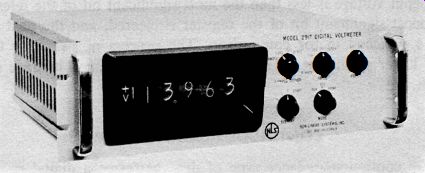
Fig. 1-1. A typical digital voltmeter.
Permanent recording instruments are available with printers, card and tape punches, and magnetic tape equipment. Data in digital form may be processed with no loss of accuracy.
BASIC OPERATING PRINCIPLES
The heart of a digital voltmeter is the circuitry which converts analog voltage to a digital form. This is known as analog-to-digital conversion or adc. Most digital voltmeters on the market today fall into one of five categories:
1. Successive approximation
2. Continuous balance
3. Ramp (voltage-to-time interval)
4. Integrating
5. Integrating and potentiometric
The basic operating principles of each of the five basic types of digital meters will be given in this section. Additional circuit descriptions are covered in later sections.
SUCCESSIVE-APPROXIMATION DVM
The successive-approximation type of digital voltmeter converts the input voltage into digital form by a series of approximations and decisions. This type of voltmeter consists of a digital storage register (digital accumulator), a digital-to-analog converter, a comparison network (error detector), a precision voltage reference, and control circuitry. The input voltage is compared first with the most significant bit. The actual comparisons are made successively in binary form. If the input voltage is less than the most significant bit of the reference, the most significant bit of the register is cleared, and the next lower bit is switched in for comparison. The process of switching to the next lower significant bit is continued until a decision is made on all digits.
CONTINUOUS-BALANCE DVM
The continuous-balance type of dvm performs a digital measurement by comparing the unknown voltage with a voltage derived from a stable reference supply. At the beginning of a measurement the unknown voltage is compared with the "full-scale" reference. If null (balance condition) is not reached, a voltage derived from the reference is reduced by an incremental value representing a unit of the least significant digit. This is done by automatic switching of the precision resistors. This process continues until null is reached.
RAMP DVM
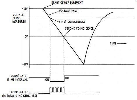
Fig. 1-2. Timing diagram of ramp-voltage generation.
The ramp (voltage-to-time conversion) category forms the economy class of digital voltmeters. The operating principle of the ramp digital voltmeter is to measure the length of time it takes for a linear ramp of voltage to become equal to the unknown input voltage, starting from a known level. This time period is measured with an electronic time-interval counter and displayed on "in-line" indicating tubes. Two advantages of this instrument are low price and simplicity. However, it requires an input noise-filter if superimposed noise is present.
Conversion of a voltage to a time interval is illustrated by the timing diagram of Fig. 1-2. At the start of a measurement cycle a ramp voltage is generated. The ramp is compared continuously with the voltage being measured. At the instant the two voltages become equal, a coincidence circuit generates a pulse which opens a gate. The ramp continues until a second comparator circuit senses that the ramp has reached zero volts. The output pulse of this comparator closes the gate. If the input is a negative voltage, coincidence with it would occur before zero coincidence. The circuitry senses which coincidence occurs first and switches the polarity indicator accordingly.
The time between the gate opening and closing is proportional to the input voltage. The gate allows clock pulses to pass into the totalizing circuits, the number of pulses counted during the gating interval being a measure of the voltage. Choice of ramp slope and clock rate enables the totalizing circuit readout to read directly in millivolts (for example, a slope of 300 volts/second and a clock rate of 300 khz).
INPUT COMPARITOR
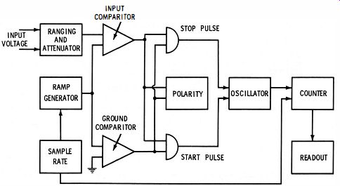
Fig. 1-3. Block diagram of a typical ramp-type dvm.
The main advantage of voltage-to-time conversion as a technique for dvm's is its simplicity. Slowly varying input voltages do not disturb the operation of the voltmeter, as often happens with null-seeking voltmeters which may continually hunt for, but never reach, a balance.
A block diagram of a typical ramp-type dvm is shown in Fig. 1-3.
Here, a voltage ramp is generated and compared with the unknown voltage, and with zero voltage. Coincidence with either voltage starts the oscillator, and the electronic counter counts the cycles. Coincidence with the second comparator stops the oscillator. The elapsed time is proportional to the time which the ramp takes to travel between the unknown voltage and zero volts, or vice versa. The order in which the pulses come from the two comparators indicates the polarity of the unknown voltage. The accumulated reading in the counter can be used to control ranging circuits.
INTEGRATING DVM
The integrating (voltage-to-frequency conversion) dvm's represent an advancement over the ramp-type units. The integrating digital voltmeter measures the true average input voltage over a fixed encoding time, instead of measuring the voltage at the end of the encoding time as do ramp-type, successive-approximation, or continuous balance units. Measurement at the end of the encoding time could easily coincide with a burst of noise, creating an inaccuracy in the ramp-type units.
Conversion of a voltage to a frequency is illustrated by the diagram of Fig. 1-4. The circuitry functions as a feedback control system which governs the rate of pulse generation, making the average voltage of the rectangular pulse train equal to the d-c input voltage.
A positive voltage at the input results in a negative-going ramp at the output of the integrator. The ramp continues until it reaches a voltage level that fires the level detector which triggers a pulse generator. The pulse generator produces a rectangular pulse with closely controlled width and amplitude, just sufficient to draw enough charge from a capacitor to bring the input of the integrator back to the starting level. The cycle then repeats.
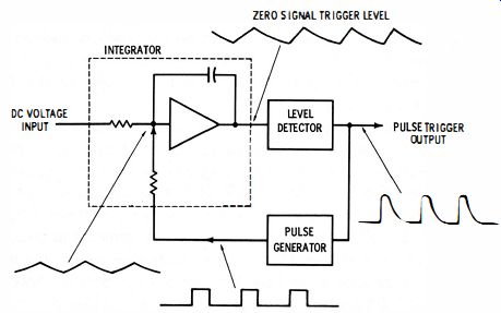
Fig. 1-4. Network for converting voltage to frequency.
The ramp slope is proportional to the input voltage. A higher voltage at the input would cause a steeper slope, resulting in a shorter time duration for the ramp. Consequently, the pulse repetition rate would be higher. Since the pulse repetition rate is proportional to the input voltage, the pulses can be counted during a known time interval to obtain a digital measure of the input voltage. Although a voltage ramp is generated in this type of dvm, the amplitude is only a fraction of a volt, and the accuracy of the analog-to-digital conversion is determined not only by the characteristics of the ramp but also by the area of the feedback pulse.
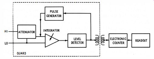
Fig. 1-5. Simplified block diagram of the guard circuit technique.
The main advantage of this type of analog-to-digital conversion is that the input is "integrated" over the sampling interval and the reading represents the true average of the input voltage. The pulse repetition frequency "tracks" a slowly varying voltage so closely that changes in the input voltage are accurately reflected as changes in the pulse repetition rate . The total pulse count during a sampling interval, therefore, represents the average frequency and thus the average voltage. This is important when noisy signals are encountered during measurement. The noise is thereby averaged out during the measurement without requiring input filters that would slow down the voltmeter response time. The voltmeter achieves essentially infinite rejection of power-line hum-the most prevalent source of signal noise--when the measurement interval is an exact multiple of the hum waveform period.
Another advantage is that the pulse circuits provide a convenient means of coupling the information out of a guard circuit. Such guard circuits are used to isolate the measuring circuit from the remaining readout circuits. Fig. 1-5 shows a simplified block diagram of the guard-circuit technique. Here the integrating digital voltmeter has a floating input, and all of the voltage-to-frequency conversion circuitry is housed within a guard shield. In other integrating dvm's, the integrator, the pulse generator, and the level detector generate a train of pulses. The total number of pulses over a specified period is directly proportional to the integral of the input signal over this same period.
This arrangement makes it possible to transformer-couple the signal to the digital circuits outside the guard, allowing complete isolation of the measuring circuit itself.
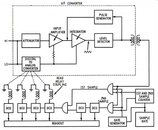
Fig. 16. Block diagram combining features of resistance ratio and stable reference
voltage.
POTENTIOMETRIC INTEGRATING DVM
The potentiometric integrating dvm combines the features of an integrating dvm and a form of differential voltmeter. (Differential voltmeters are discussed in later sections.) A conventional integrating dvm measures the true average of the input voltage over a fixed encoding time. A conventional differential voltmeter relies primarily on resistance ratios and a stable reference voltage to ensure accuracy.
It is possible to combine these two basic features, as shown in the block diagram of Fig. 1-6. Such a voltmeter is divided into three sections : a voltage-to-frequency (v/f) converter, a counter, and a digital-to-analog (d/a) converter. Readings are taken in two steps. First, the v If converter generates a pulse train with a rate proportional to the input voltage. This pulse train is gated for a precise time interval and is fed to the first four places in a six-digit counter. The stored (un-displayed) count is transferred to the d/a converter, which produces a highly accurate d-c voltage proportional to the stored count. This voltage is subtracted from the unknown voltage at the input to the v If converter.
The next step in operation occurs when the pulse train from the v If converter is again gated a second time going to the last two places in the six-digit counter. At the end of the second gate period the total count is transferred to the six display tubes. The counter display is indicative of the integral of the input voltage.
ELECTROMECHANICAL DIGITAL METERS
In addition to the all-electronic digital meters, there are a number of electromechanical units in current use. These can be classified into four general types-stepping switch, relay, analog-servo, and strobo-scoping.
Stepping-Switch Type
The stepping-switch instruments are of the comparison type in which a stepping-switch-operated voltage divider creates a feedback voltage equal to the input voltage (see Fig. 1-7). The two major differences between the various stepping-switch digital voltmeters are the sequence (logic) in which they develop the feedback voltage and whether the stepping switches are run dry or kept continuously lubricated by immersion in a bath of oil. The difference is extremely important. The proper type of logic ("scan" logic rather than "tracking" logic; see Glossary) and oil immersion can greatly increase instrument life. The "scan" logic also increases measuring speed and eliminates hunting, which is a disadvantage of the "tracking" instruments.
More stepping-switch digital voltmeters have been produced than any other kind. They are low priced with respect to their accuracy, which is on the order of ±0.01 percent of full scale. They are simpler in construction than any other instrument in this accuracy class and are relatively simple to maintain, providing such features as plug-in stepping switches are incorporated.
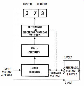
Fig. 1-7 Voltage divider for creating a feedback voltage equal to the input
voltage.
The average time per measurement of a four-digit instrument with tracking logic is 1.0 second compared with 1.9 seconds maximum for a four-digit instrument with scan logic. An advantage of the stepping switch type of instrument is that electrically isolated digital outputs in contact-closure form are obtained by adding another deck to each stepping switch.
Relay Type
The relay-type instruments are comparison units in which a relay operated voltage divider creates a feedback voltage equal to the input (Fig. 1-7). Relay-type digital voltmeters are capable of higher speed than the stepping-switch type since the relays can be operated at a higher speed (100 steps per second rather than 30 steps per second). They can be operated in any sequence (in a stepping switch, the switching sequence is fixed). Some relay-operated instruments make three measurements per second, which compares favorably with the speed of some "all-electronic" instruments having automatic ranging.
Analog-Servo Type
In the analog-servo type of instrument a feedback voltage is created by a motor-driven variable resistance (potentiometer). Its functional diagram (Fig. 1-8) resembles that of a servo system used for positioning an output shaft (position servo). That is, a balance detector compares the input and feedback voltages and issues commands which are amplified to drive the motor. The motor drives the variable resistance in the proper direction to make the feedback voltage equal to the input. When the feedback and input voltages are equal, the balance-detector output voltage ideally drops to zero, and the motor stops. Voltage readout is in terms of motor shaft position and is displayed by a calibrated drum or several numbered drums, each geared to the adjacent drum by a mechanical transmission having a 10: 1 drive ratio.
Analog-servo digital voltmeters are in the same speed class as the slowest stepping-switch instruments. Usually, initial accuracy is about 0.1 percent to 0.5 percent of full scale. Initial accuracies on the order of ±0.0 1 percent can be achieved at high cost by using a very precise, motor-driven variable resistance. Digital output, for driving printers and other output accessories, can be obtained if an analog-to-digital shaft-position converter is coupled to the drive motor; this will, however, increase overall instrument cost significantly. Automatic ranging is not normally available with analog-servo type instruments.
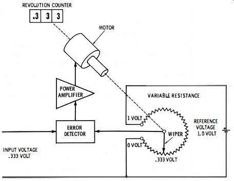
Fig. 1-8. Functional diagram of the analog servo type of instrument.
Stroboscopic Type
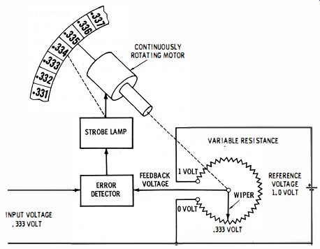
Fig. 1-9. Generation of the ramp voltage.
This stroboscopic-type device is somewhat similar to the ramp-type all-electronic instrument. It generates a ramp voltage by continuously rotating the wiper of a variable resistance (potentiometer) which is energized by a d-c reference voltage (Fig. 1-9). The ramp voltage is compared continuously with the input signal so that each time the two voltages are equal a lamp is flashed, illuminating a numbered drum coupled to the shaft of the rotating pot. The numbers aligned with a small window in front of the drum are made visible by the flashing lamp at the time of voltage equality. The drum speed is high enough (1500 rpm) to produce numbers which appear to be stationary.
The price of stroboscopic instruments is relatively low. Readout numeral size is limited by the overall instrument size. Initial accuracy is in the order of 0.5 percent of full scale. However, the high-speed rotation of the variable resistance wiper poses a life problem, and digital output and automatic range changing are not offered in these instruments. A relatively low input impedance (1 megohm) is provided.
SELECTING A DIGITAL METER
There are many factors that should be considered when selecting a digital meter. The following is a summary of these factors.
Measuring Speed
Of course, all digital voltmeters are very fast compared with pointer meters and manually balanced potentiometers. But speed varies among the basic types, ranging in balancing time from two seconds to several microseconds. Consider carefully whether you require more than one reading per second since relatively few applications require such balancing speed. Unless you are prepared to spend thousands of dollars, you will generally be sacrificing accuracy, reliability, or versatility to achieve the higher speed.
There are two general types of applications requiring high-speed measurements. One such application is when a large number of readings must be made in a short period; the other is when one reading must be made at a definite instant in time.
Examples of the former type of application are defining the waveshape of transients and measuring many channels of data quickly before test conditions change or when the quantity of data is so large as to require an inordinate time for data collection (applications which involve sampling 1000 channels of data require more than 17 minutes per complete cycle for a one-reading-per-second digital meter). Examples of the latter type of application include measuring a varying voltage at a definite instant in time so that voltage data can be correlated with other data such as time, distance, etc., as in radar tracking stations. For this type of application, a special digital voltmeter known as a sample-and-hold type should be considered. Sample-and-hold models are designed to "follow" input variations until commanded to read, whereupon they hold the input voltage constant (internally) for that instant while it is measured. Such digital voltmeters can provide much greater accuracy in this application than very high speed digital meters can without the sample-and-hold feature.
Reducing overall speed requirements can sharply reduce the cost and complexity of data logging systems and reduce procurement lead time, too. For example, a data printer capable of five recordings per second costs approximately $1500, while one capable of 300 recordings per second costs from $30,000 to $50,000. The cost of high-speed input scanners and other data logging input and output devices rises sharply with speed.
Consider the fact that the digital voltmeters with tracking logic have a very long balancing time when the input signal varies, unless they are desensitized-in which case accuracy is reduced.
Accuracy
Obviously, the manufacturer's statement of accuracy is not always sufficient. Basic questions include the following: How often must you correct for long term drift in calibration or zero point? When subjected to varying input signals, will the instrument display a value that the input signal actually had during the balancing cycle? Instruments with scan logic will; instruments with tracking logic may not.
When selecting the number of digits needed in a digital voltmeter, consider the limitations of digital resolution. In a four-digit digital meter, a reading at 20 percent of full scale (2000 volts, 20.00 volts, 200 volts) can only be accurate to ± 1 digit, which is one part in 2000 or 0.05 percent of the value read. A reading at 10 percent of full scale (1000 volts, 10.00 volts, 100.0 volts) can also be accurate to ± 1 digit, which is one part in 1000, or 0.1 percent of the value read.
Therefore, it is advisable to select a five-digit meter if close to 0.01 percent accuracy is required over most of the measuring range. Select a three-digit meter only if one-percent accuracy is acceptable.
Reliability
Reliability cannot always be judged on the basis of price alone.
Rather, look closely at the type of construction and the more subtle clues-quality of components and derating of components. For ex
ample, does the stepping-switch type meter have stock telephone switches or the type specially designed for digital voltmeter use? Do switches have phenolic insulation or diallyl phthalate, which protects the instrument accuracy against the effects of moisture? Are there excessive solder joints and cable connections? Are long-life, mercury wetted contact relays used? Often it is wise to either check with present users about the reliability which they have observed with the instrument or request all manufacturers to submit a sample for test.
Versatility
Suppose that you require voltage-ratio and resistance measurements, in addition to voltage measurements, and also require data recorder operation. A multipurpose instrument with built-in circuits designed to perform all of these functions may be lower in cost, more reliable, and much more convenient to use. One which was designed as a digital voltmeter and requires wiring changes or additional modules to convert it for voltage-ratio and resistance measurements, or to convert it for use with data recorders, may be cumbersome.
Ease of Operation
An inherent advantage of digital voltmeters is the ease of operation; however, some are easier to operate than others. For example, some instruments do not require desensitizing if the input signal varies during measurement-their logic always produces a reading as accurate as the voltage is stable.
Ease of Servicing
The ease of servicing is an often overlooked factor which deserves major consideration. Some questions to ask here are : How long does it take to replace a stepping switch? How much of the construction is plug-in? How fast can a readout bulb be replaced? Are spare parts and assemblies readily available? Does the manufacturer offer maintenance training locally, or must you travel across the nation to get it? Does the manufacturer offer servicing at regional offices as well as at the main plant?
DIGITAL VOLTMETER LOGIC
Digital meter logic is the sequence in which the digital voltage divider switches or circuits and the range and polarity circuits operate in making a measurement. Logic is important because it affects meter speed, life, and response. In digital ratio-meters reaction to reference voltage changes is also important.
The two forms of logic used in most digital meters are successive trial or scan logic and tracking or digital servo logic.
Scan Logic
The distinguishing feature of feedback-voltage creation in scan logic meters is that the output voltage of each decade is scanned, or sampled, in a definite sequence, and the decade switches are operated once per measurement, starting with the leftmost digit and progressing to the right. Some digital meter manufacturers (such as Non-Linear Systems, Inc.) designate this type of logic as "no-needless-nines" logic when used in stepping-switch meters because it eliminates needless cycling of the switches through their nine and zero positions. Scan logic is also frequently used in relay and all-electronic digital meters.
Double Scan Logic
This form of scan logic (also called doubLe duty no-needLess-nines logic or tracking scan logic-not to be confused with "tracking" logic) is of particular benefit in stepping switch meters. It affords such meters all the benefits of ordinary scan logic, plus the one operating advantage that tracking logic meters have. This is the capability of displaying a one-digit increase in voltage very quickly (in ordinary scan logic, the positions of the polarity and range switches or circuits, and all left-most decade switches must be sampled-but not changed--before the rightmost decade switch position can' be changed). In starting a measurement with a double scan-logic meter, the logic first determines (without moving stepping switches) which decade or decades must be changed. Then, numerical changes are made, starting with the left-most decade, which requires a change and progressing to the right.
Each stepping switch cycles no more than once per reading; if a switch does not have to change, it does not cycle.
For example, consider a change from 9.326 to 9.327. In double scan logic the 6 can be changed to a 7 almost immediately because in double scan logic the rightmost decade is sampled before all others.
In ordinary scan logic, the polarity switch position, range switch positions, and the three leftmost decades must all be sampled (but not changed) before the 6 can be changed to a 7. However, the double scan logic still has all the advantages of ordinary scan logic : no decade switch will cycle more than once per reading; only those decade switches that must be changed to create new numbers will step; the instrument will not hunt when the input varies during measurement, and the meter automatically adapts to a wide range of reference voltage for voltage-ratio measurements. Best of all, no adjustments are necessary.
Tracking Logic
Despite the many advantages of the scan logic, tracking logic is still used in low-cost digital meters. The most characteristic feature of tracking logic is that decade switches are always free to follow any input signal change that occurs (unless the decade switches are turned off) and that all of the readings are then computed starting with the least significant (rightmost) decade and progressing from the right to the left.
If the input voltage is greater than the feedback voltage, the meter error detector issues "up" pulses to stepping switches which operate each decade of the feedback divider. If the feedback exceeds the input, the error detector issues "down" pulses to these same stepping switches which are on a separate logic-pulse line. (See Figs. 1-10 and 1-11.)
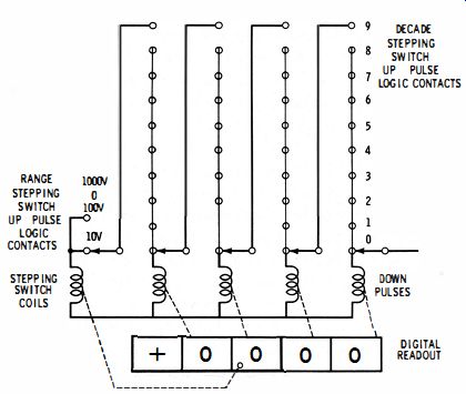
Fig. 1-10. Routing of "up" pulses.
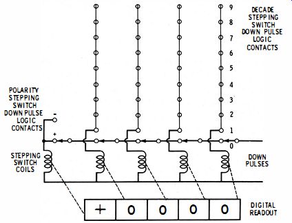
Fig. 1-11. Routing of "down" pulses.
DIGITAL VOLTMETER ACCURACY STATEMENTS
The accuracy statements of digital voltmeters are somewhat different from those of conventional analog meters. "Percent of full scale" is usually synonymous with "percent of full scale of range in use." These terms indicate an error that is of fixed amplitude over each range. An error of "0.01 percent of full scale of range in use" is an error of 0.00 1 volt for any reading on the 9.999-volt range, 0.01 volt on the 99.99-volt range, etc.
An error expressed as "percent of reading" indicates an error whose absolute value is governed by the value of the measurement. An error of "0.01 percent of reading" means an error of 0.0009 volt in a 9-volt measurement, 0.00009 volt in a 0.9-volt measurement, etc.
An error of "one digit" also called "one least count" or "one count" means an error the size of the smallest increment displayable by the digital instrument. A one-digit error means an error of 0.001 on the 9.999 range, 0.01 on the 99.99 range, etc.
Errors must sometimes be expressed in mixed quantities. To visualize the total size of the error, convert to some common quantity, such as volts. For example, in measuring 5.000 volts with a four-digit meter whose accuracy is "0.01 percent of reading plus one digit," the maximum error is 0.01 percent of 5 volts, plus 0.00 1 volt, or a total of 0.0015 volts.