AMAZON multi-meters discounts AMAZON oscilloscope discounts
The Problem
The bulk of electrical energy, more than ninety percent, is generated and transmitted as alternating current and is used to operate household appliances, alternating current motors, electric furnaces, and electrical lighting systems. The chief reasons for generating the electrical energy with an alternating waveform are:
A. Alternating electrical energy can be easily generated at high voltage. By employing high voltage, economical transmission of electrical energy over long distances is accomplished. If this high voltage is alternating in waveform, it is readily reduced in voltage at the application end of the transmission by means of efficient, non-rotating electrical step-down devices called transformers.
B. It is desirable to have electrical energy available in alternating waveform so as to be able to employ alternating current motors of the induction type which are cheaper, more efficient, and trouble free than direct current motors. These induction motors are used in great numbers in industry and in domestic appliances and systems, for example, fans, heating and ventilating systems, phonographs, and magnetic tape recorders.
C. It is more economical to generate electrical energy in large units at a central powerplant than to generate it in small units near the point of utilization. Only alternating electrical energy lends itself to the remote generation and the economical transmission in large units.
Despite these good reasons for the almost universal presence of electrical energy in the alternating waveform, there are many electrical products and techniques which require direct current for efficient operation and control. Common applications where direct current is necessary are: AC-DC radio power supply Acoustic shunt Aircraft engine starting Aircraft power supply Arc suppressors Arc welders Automotive rectifiers Battery chargers Battery eliminators Burglar alarms Business machines Computers Carbon arc lamps
Carrier control
Cathodic protection Chemical testing Circuit breakers Coin machines DC solenoids DC magnets Electro cleaning Electro etching Electro painting Electro plating Electro precipitation Electric hammers Elevator controls and brakes Engine starters Exciter lamps Fence controls Field excitation Filament supply Fire alarms Inductive surge absorber Lifting magnets Magnetic amplifiers Magnetic brakes Magnetic separators Magnetic valves Magnetic clutches Model trains Oscillograph power supply Plate voltage power supply Polarized relays Proximity fuses Railway signaling Rectifier instruments Relays Telegraph power supply Telephone power supply Television power supply Time clocks Traffic control Trickle charger Truck chargers Voltage multipliers Vibrator feeders
When direct current is needed, it must generally be obtained from the universally present alternating current system.
The alternating current must be converted in some manner into direct current. This conversion of alternating current into direct current is called rectification and may be accomplished in the manners to be described.
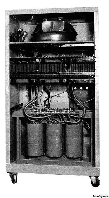
------------ Frontispiece, Rear View of Rectifier Cabinet for Elevator Control.
(Courtesy of W. Green Electric Company, Inc., New York.)
The Mechanical Approach
Mechanical rectifiers have been used to convert alternating current into direct current. Fig. 1-1 shows one method of accomplishing this mechanically. A synchronous motor M drives a shaft S upon which are mounted two slip rings A and Band a two segment commutator C having segments x and y.
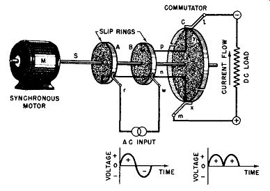
Fig. 1-1. A Mechanical Rectifier (Full Wave).
The slip rings and the commutator segments are insulated from the shaft. A conductor n connects slip ring A with commutator segment x while a conductor p connects slip ring B with commutator segment y. Brushes r and w engaging the slip rings A and B apply the alternating current to the rotating system. Brushes l and m, engaging the commutator segments as they rotate, provide the commutated direct current to the load. The reader can follow that the synchronously driven system provides direct current flow through the load circuit; for, at that instant when the alternating input polarizes brush r positive and brush w negative, the output brush m is positive while the output brush 1 is negative. One half cycle later (one half revolution of the commutator and slip rings because the mechanical system is synchronous with the alternating voltage which is driving the synchronous motor) brush r is negative while brush w is positive. Because the commutator has rotated one half of a revolution by this time too, brush r now energizes brush 1, whereas brush w now energizes output brush m.
Thus the output brush polarities remain unchanged and a direct current flows through the load with the polarity as shown. That is, the commutator segments are connected as shown so that, when the alternating input reverses, the connections to the direct current or output circuit are simultaneously reversed resulting in a direct current output. The voltage-time curve shown below the AC input in Fig. 1-1 illustrates the sinusoidal input voltage or current; the curve below the DC load illustrates the fully commutated AC input resulting in a direct current flow of varying amplitude.
The disadvantages of the mechanical rectifier are that the moving parts require frequent maintenance, and practical considerations of applied voltage and sparking at the brushes limit the device to small current and voltage outputs.
The Vibrating Reed Rectifier

Fig. 1-2. A Vibrating Reed Rectifier (Full Wave).
The vibrating reed rectifier is also mechanical in nature and operates on the same basic principles as the mechanical or rotating rectifier just described. In the vibrating rectifier, however, a pair of contacts are reciprocated between two sets of stationary contacts by means of a tuned reed or armature, which is synchronously driven by the alternating current to be rectified. To drive the reed at synchronous speed it is necessary for it to be magnetically polarized. This is accomplished by means of a permanent magnet slug mounted in a favorable position in the magnetic circuit of the vibrating rectifier. The schematic diagram of the vibrating reed rectifier is given in Fig. 1-2. The tuned reed m carries a pair of contacts, u and v, which are insulated from each other and from the reed. The electromagnet E which is part of the magnetic circuit (not shown) vibrates the moving contacts u and v between the pairs of stationary contacts R S and L N. The vibration is synchronous because the magnetic circuit is energized by the same alternating current which is to be rectified.
The moving contacts are connected each to a respective terminal of the AC input. The stationary contacts are cross connected, that is, R to N and S to L with the common connection between each becoming the positive and negative terminals of the DC output.
Thus, during that part of the alternating cycle when the AC input polarizes contact u negative and contact v positive, the electromagnet E may be so connected as to attract the magnetized reed to the right causing contact u to engage fixed contact L while contact v engages fixed contact N. The upper output terminal is then negative while the lower output terminal is positive. During the next half cycle when the movable contact u is positive and movable contact v is negative, the electro magnet E also has its magnetic polarity reversed because of the change in the polarity of the applied alternating input, thus causing it to repel the reed m and permitting the movable contacts u and v to engage the fixed contacts R and S respectively.
Because of the cross-connections between the fixed contacts, that is, R strapped to N and S strapped to L, the alternating input is mechanically commutated so that the upper output terminal is maintained negative while the lower terminal is maintained positive. Hence, the output of the vibrating reed is direct current of varying amplitude. Again the graphs near the input and output show the waveform of the current flow or voltage present at those terminals respectively.
Moving parts and small output have limited the use of this rectifier which was formerly used to charge small storage batteries. At the present time a modified form of this vibrating-reed rectifier operated synchronously with a vibrator chopper permits the operation of automobile radios from the car storage batteries.
The Chemical Approach
Another type of rectifier formerly used to change alternating current to direct current is of the chemical or electrolytic type, See Fig. 1-3. This rectifier consists primarily of a lead plate electrode and an aluminum plate electrode immersed in a solution of sodium bicarbonate or ammonium phosphate contained in a glass jar. When the electrolytic cell is energized so that the lead plate is positive and the aluminum plate is negative, electrical current flows readily. When the applied potential to the electrodes of the electrolytic cell is reversed, that is, the lead plate is made negative and the aluminum plate positive, a thin insulating film of aluminum oxide forms instantly over the aluminum electrode and acts as an insulator up to a breakdown voltage of approximately 150 volts. This oxide film prevents the flow of electrical current when the aluminum plate is positive and the lead plate is negative, provided the breakdown voltage is not exceeded. The resulting unidirectional conduction of the electrolytic cell makes it behave as a rectifier.
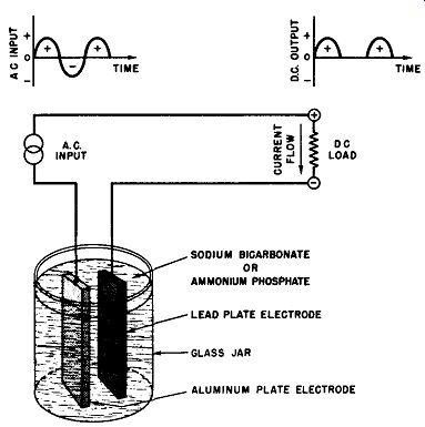
Fig, 1-3. An Electrolytic Rectifier (Half Wave), SODIUM BICARBONATE OR AMMONIUM
PHOSPHATE LEAD PLATE ELECTRODE ALUMINUM PLATE ELECTRODE
In the arrangement shown in Fig. 1-3 wherein a single electrolytic cell is used, half-wave rectification occurs, that is, every other half cycle of the alternating current is per mitted to flow through the DC load. It is necessary to employ two such cells with a center-tapped transformer as in Fig. 1-4A, or four such cells in a bridge circuit as in Fig. 1-4B, before full-wave rectification ( unidirectional current flow from both negative and positive alternations of the alternating current waveform) can be accomplished. Circuit details in connection with any type of rectifier cell used in half-wave and full-wave will be thoroughly discussed in the section dealing with "Rectifier Circuits."
Small current capacity, low efficiency, as well as the generally messy nature of the electrolytic cell rectifier have limited the use of this means of rectification.
(A) Using Two Cells and a Center-Tapped Transformer.
(B) Using Four Cells in a Bridge Circuit.
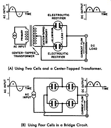
Fig. 1-4. Full Wave Rectification with Electrolytic Cells.
The Motor-Generator Approach
Alternating current motor-driven DC generators have also been used to indirectly change AC to DC by means of an electromechanical transfer. These arrangements have been and are still being used in some electroplating organizations.
Electroplating service is a low-voltage, high-current application and the efficiency of motor-generator combinations is low at low output voltages--of the order of 25 to 30 percent.
For full output voltage the efficiency of the motor-generator combination may approach 60 to 80 percent. Moreover, the motor-generator combination requires frequent overhauling and attention to the brushes and commutator, for it is difficult to protect it from the corrosive electroplating fumes as the machine must be mounted near the point of application to se-cure short copper bus bars to the job. Short bus bars are essential so as to minimize the electrical losses which would be excessive as a result of the heavy current employed for plating.
Mercury Arc Rectifiers
For the abundant rectification of alternating electrical energy, especially in the metal manufacturing industries, very large mercury-arc rectifiers of the glass enclosure or steel tank construction have been used. Small mercury-vapor rectifiers have been used for battery charging for 40 years. Some examples of small mercury-vapor rectifiers available for general purpose rectification at high voltages and moderate current of the order of 10 to 15 amperes are shown by the sketches of Fig. 1-5. Large mercury-arc rectifiers have been constructed with capacities up to several thousand kilowatts.
The large glass type mercury-arc rectifiers are obsolete today and the steel tank type mercury-arc rectifiers are being superseded by the ignitron, fundamentally, a mercury-arc tube containing in addition an igniting electrode and the necessary associated actuating circuits.
(A) Screw-Bose Mercury-Vapor Rectifier.
(B) Flexible-Lead Mercury-Vapor Rectifier.
(C) Symbol for Mercury-Vapor Rectifier.
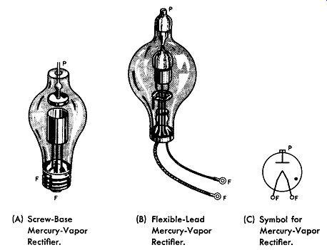
Fig. 1-5. Small Mercury-Vapor Rectifiers Rated at 10 to 15 Amperes.
The Metallic or Dry Disc Rectifier
Another type of rectifier, the subject of this guide, is the metallic or dry disc rectifier. This type of rectifier has be come widely accepted because of its simplicity, absence of moving parts (hence, negligible maintenance), silent and instantaneous operation, practically unlimited life, and low cost.
The metallic rectifier is identified by a variety of names still in common usage. The original rectifier cells were fabricated from discs, hence, the title "dry disc rectifier". Still later some manufacturers started using square or rectangular plates for the rectifier cells, originating the noun "dry plate rectifiers". In recent years, as the mechanism of the metallic rectifier is becoming better understood, some people have emphasized one of its important elements by calling the device a "semiconductor rectifier". The communication engineers call the metallic rectifier "varistors", more specifically "non symmetrical varistors" defining a varistor as "a two-terminal circuit element composed of an electronic semiconductor and suitable contacts which has a markedly nonlinear volt-ampere characteristic".
The National Electrical Manufacturers' Association has identified the rectifier under discussion as metallic rectifier and this term is the name which was selected to identify it in this guide.
The basic principle of the metallic rectifier for converting alternating current into direct current is that the resistance to the passage of electrical current in one direction is exceedingly great, whereas the resistance to the flow of electrical current in the opposite direction is almost negligible. The result is that, when an alternating potential is applied across a series circuit comprising a metallic rectifier and a load, the current flow is substantially unidirectional--the metallic rectifier performs as a one-way valve for the alternating current.
Certain combinations, such as iron or aluminum and selenium, magnesium and copper-sulphide, or copper and copper-oxide have this valuable property of passing an electric current uni-directionally; because of this property, these combinations are used as rectifiers or converters of alternating into direct current.
In so far as the writer is aware the original discovery of the metallic rectifier was made in November, 1920, by L.O. Grondahl and P. H. Geiger of Union Switch and Signal Company. The first type of rectifier involved copper and copper-oxide elements.
The discovery that a copper-copper oxide junction had rectifying characteristics was the by-product of another re search problem under study at that time. This problem was to produce an electrical relay without moving parts or contacts.
The experimental procedure for this research was to study all forms of electrical impedance which could be easily and non mechanically changed through a large resistance range to simulate the opening and closing of electrical contacts as by relay contacts.
One of the experiments towards achieving non-mechanical relays involved photoelectric cells using selenium or copper oxide. The copper oxide was selected for the tests since its properties had been more stable during previous laboratory experiments.
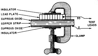
Fig. 1-6. Exaggerated Cross-Sectional View of Original Copper-Oxide Type,
Half-Wave, Metallic Rectifier.
The first experimental model of the relay comprised a strip of copper which had been heated in an electric furnace at about 1000 degrees centigrade for one hour. A connection to the copper plate was made by breaking off the cuprous oxide at one end. The cupric oxide on the surface of the copper strip which had formed during the cooling was ground off by an emery wheel. Contact to the surface of the cuprous oxide was obtained by means of a piece of lead sheet compressed against the cuprous-oxide surface by means of a clamp. Sheets of insulator material at either side of the assembly prevented short circuit of the test junction due to the metal clamping means used. See Fig. 1-6.
This assembly was tested by means of a Wheatstone bridge energized by direct current so as to determine its resistance with and without light falling upon the active cuprous oxide surface. It was hoped that light falling upon the active surface would greatly reduce the normally high resistance-simulating the non-mechanical actuation of a circuit switch.
Wheatstone bridges are commonly used in the laboratory for resistance measurements and the circuit diagram with the essential operating equation is shown in Fig. 1-7. Ra and Rb are predetermined fixed resistances and are called the ratio arms of the bridge. The unknown resistance, Rx, is connected to the test terminals of the Wheatstone bridge. The fourth arm of the bridge consists of a variable, but known resistance Rs, in the nature of decade resistance boxes or a calibrated resistance slide wire. Across one diagonal of the resistance bridge is connected the electrical energizing means, a low voltage battery. Across the other diagonal of the bridge is connected in series a galvanometer switch and a galvanometer.
The adjustable known resistance, Rs, is varied until there is no difference of potential across the diagonal containing the galvanometer. This condition is detected when closure of the galvanometer switch does not result in a deflection of the galvanometer pointer from its null position. When Rs is adjusted to achieve null balance the potential drop across Ra and Rx is equal to the potential drop across Rb and Rs. This condition is necessarily so if there is to be no difference of potential across the galvanometer.
Hence,
Rx Ra
=--
Rs Rb
or
Rx = Ra
Rs.
Rb
When measurements on the experimental copper-copper oxide assembly were made by means of the DC Wheatstone bridge, it was found that the photoelectric effect was nil, but a peculiar effect was discovered. At times the experimental assembly measured a resistance of 400 ohms and at other times the assembly measured 1200 ohms. It was soon determined that the resistance value of the assembly depended upon the polarity of the battery powering the Wheatstone bridge or upon the way in which the assembly was connected to the bridge, that is, whether the assembly was connected to the bridge so that the copper electrode was connected to terminal A and the copper oxide electrode to terminal B or vice-versa.
Refer to Fig. 1-7.
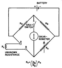
Fig. 1-7. A DC Wheatstone Bridge for Measuring Unknown Resistances.
The two values of resistance measurement indicated a non-symmetrical conduction of electrical current through the experimental assembly and this copper copper-oxide combi nation was recognized as a potential rectifier of alternating current. Because the available rectifiers of the early 1920' s were bulky, unstable, or difficult to use and consisted of rotating or vibrating mechanisms or chemical cells already described, and because there was a need for a simple and reliable rectifier for the operation of a DC relay from an AC source, the copper-oxide combination was further improved. By 1924 a practical installation was made in a train control equipment which actuated a DC relay from an AC supply. As late as December, 1947, this rectifier was still operating in the same application.
Another pressing problem of those days accelerated the development of this accidental finding. In the early 1920' s the filaments of vacuum tubes used in radios were energized by means of 6-volt storage batteries which were called "A" batteries. These "A" batteries required chargers to maintain them as sources of electrical energy. During the latter part of 1926 the Westinghouse Electric Corporation was producing 6000 "A" battery chargers a day employing copper oxide assemblies.
In the succeeding years the magnesium-copper sulphide and the selenium rectifiers were developed by others and commercially applied. Currently the design and application engineer has a choice of the three types of metallic rectifiers.
Certain advantages or properties of one of the types may help in the decision of which of the three to use for a specific application. These properties will be described in later sections of this guide.