AMAZON multi-meters discounts AMAZON oscilloscope discounts
Introduction
The need for conversion of alternating current into direct current was discussed in Section 1. Various methods for this conversion were described involving mechanical, chemical, and gaseous vapor and arc tubes. A short history of the discovery of the metallic rectifier was given and it was stated that this type rectifier was to be the subject matter of this guide. By means of this device efficient and inexpensive rectification of alternating current into direct current is obtained for all but huge amounts of electrical energy as used in the metal industries.
In this section, some of the general properties of the metallic rectifier will be described before presenting the three specific types of these rectifiers commercially available; these three types are the copper-oxide, the magnesium-copper sulphide, and the selenium.
Some Conventions and Nomenclature
Although there is presented at the end of the guide an abbreviated section on nomenclature and standards on metallic rectifiers, it is thought best to define here some of the more pertinent conventions and rectifier terminology.
Electric Current Flow. The conventional direction of electric current flow in the circuit external to the applied potential is from the positive to the negative terminal.
Electron Flow. In a circuit the electron flow is from the negative terminal of the applied potential to its positive terminal.
Conductor. Substances in which the electrons are able to pass readily from atom to atom under the influence of a small applied potential are called conductors; examples of conductors are silver, copper, aluminum, etc.
Insulator. Substances in which the electrons are so tightly bound that it takes enormous electric potential to cause current flow are called insulators; examples are ceramics, glass, and mica.
Semiconductor. Substances which are not good conductors and yet are not insulators are called semiconductors; examples are carbon, metal oxides, and certain alloys.
Rectifier. A rectifier is an electrical device for converting alternating current into direct current; it possesses this property because it conducts current effectively in only one direction.
Metallic Rectifier. A rectifier utilizing the non symmetrical conduction of the junction between dissimilar solid conducting substances to obtain unidirectional flow of electric current is called a metallic rectifier. It is also frequently called a "dry-disc rectifier", a "dry plate rectifier", or a "semiconductor rectifier". Cell. The elementary metallic rectifier having one positive electrode and one negative electrode between which is located a single rectifying junction is called a cell. It may also be called a rectifier plate, rectifier element, or a rectifier couple.
Rectifying Junction. The region in a metallic rectifier cell which possesses the unidirectional conductivity is called the rectifying junction. It is also called the barrier or blocking layer.
Forward Direction. The forward direction of a metallic rectifier is the direction of least resistance to current flow through the cell. With conventional current flow the forward direction is from positive to negative.
Reverse Direction. The reverse direction of a metallic rectifier cell is the direction of greatest resistance to current flow through the cell; with conventional current flow the re verse direction is from negative to positive.
Rectifier Stack. A rectifier stack comprises a single columnar assembly of one or more metallic rectifier cells.
Half-Wave Rectification. Half-wave rectification is rectification wherein only one half of the alternating cycle is transmitted as unidirectional current.
Full-Wave Rectification. Full-wave rectification is rectification wherein both halves of the alternating cycle are transmitted as unidirectional current.
The Generalized Metallic Rectifier It will be seen later in the guide that the three commonly used metallic rectifier cells can be simply represented by a generalized rectifier element comprising four essential components. In the generalized rectifier element the specific identification of these components will not be necessary (specific examples will be given in subsequent sections); hence, simplified discussion of theory and structural nature of the various rectifier stacks can be given without a confusing recitation of the different metals, alloys, and semiconductors employed.
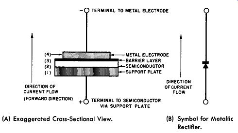
Fig. 2-1. The Generalized Metallic Rectifier Element. (A) Exaggerated Cross-Sectional
View. (B) Symbol for Metallic Rectifier.
This generalized metallic rectifier element is shown in Fig. 2-1. Fig. 2-1A representsanexaggeratedeross-sectional view of the rectifier cell and Fig. 2-1B represents the electrical symbol for the rectifier cell. The generalized metallic rectifier cell is made up of the following four essential components:
1. A metal support plate which does not enter into the rectification process but provides a mechanically strong and stable plate for the rest of the rectifier and serves as one of its terminals.
2. A semiconductor layer the nature of which depends upon the specific rectifier type.
3. A barrier, blocking, or insulating layer which is formed electrically or by heat treatment.
4. A metal electrode making intimate contact with the barrier layer by either plating, metallic spraying, or by mechanical pressure.
In a typical rectifier cell the whole cross-sectional thickness need not be more than 1/16th inch or less. This will give the reader some measure of the amount of exaggeration in Fig. 2-1A which is not drawn to scale, especially the barrier layer, which in reality is extremely thin.
The pertinent structure of the metallic rectifier cell then is a semiconductor layer separated from a metal electrode by an extremely thin insulating layer, called the barrier or blocking layer. The opposite surface of the semiconductor is in contact with a low resistance metal plate which does not function in the rectification act, except as an electrode and stable supporting means for the semiconductor.
This assembly, as described, has the unique property of readily permitting the flow of electric current in one direction through the rectifier cell, but substantially blocking the flow of electric current in the reverse direction through the rectifier cell. With conventional current flow, defined as from :he positive polarized terminal to the negative polarized terminal, the rectifier element described possesses low resistance to electric current flow in the direction from the semiconductor to the metal electrode {defined as the forward direction) and offers high resistance to the flow of electric current flow in the direction from the metal electrode to the semiconductor (defined as the reverse or bucking direction). The arrow to the left of Fig. 2-1A indicates the forward direction when the terminals of the rectifier cell are polarized as shown. Like wise, in the symbol for the rectifier cell shown in Fig. 2-1B as a bar and an arrowhead, the arrowhead indicates the for ward direction.
In a practical rectifier cell the ratio of forward resistance to the reverse resistance under rated operating conditions may be as high as 1 is to 2000. That is, for a given voltage it is 2000 times easier for the electric current to flow from the semiconductor to the metal electrode than in the re verse direction-from the metal electrode to the semiconductor. Hence, the device described performs substantially as a one-way valve to electric current flow. This is the property required of the device to make it function as a rectifier convert alternating current into direct current. The higher the resistance ratio between the reverse and forward direction, the more efficient the rectifier cell.
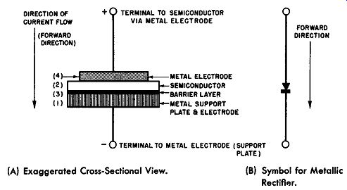
Fig. 2-2. The Modified Generalized Metallic Rectifier Cell. (A) Exaggerated
Cross-Sectional View. (B) Symbol for Metallic Rectifier.
Some people think of metallic rectifiers as comprising three essential parts in place of the four listed previously, that is, the semiconductor and two suitable electrodes. The barrier layer is not mentioned since it is not tangible nor added physically during the manufacturing process but is derived by electroforming or by heat treatment. However, the presence of the barrier layer is absolutely essential to the successful operation of the metallic rectifier and in this guide will be included as a necessary member of the rectifier cell.
Moreover, the exact position of the barrier layer is not always self-evident. It may be positioned as shown in Fig. 2-1 or as in Fig. 2-2. Both types of rectifier cells are commercially available and both generalized rectifier cells, as shown in Figs. 2-1 and 2-2, are electrically equivalent. The only difference between the two cells is in the location of the barrier layer. In Fig. 2-1, previously described, the barrier layer is located between the metal electrode and the semi conductor layer. A good example of this cell is the selenium rectifier cell. In Fig. 2-2 the barrier layer is located between the support plate and the semiconductor; an example of this type cell is the copper-oxide rectifier.
The position of the barrier layer determines the forward direction of current through the metallic rectifier cell. To avoid confusion, as each type of rectifier is presented in subsequent sections, there will be given an exaggerated cross sectional view of its rectifying components together with the correct forward direction.
The reader may remember the following general rule regarding present-day commercially available metallic rectifiers irrespective of the arrangement of the rectifying junction components. The forward direction or direction of substantial current flow in a metallic rectifier occurs when the applied polarizing potential is directed from the semiconductor to the adjacent metal across the barrier layer.
Rectification in a metallic rectifier occurs at the rectifying junction called the barrier or blocking layer. This layer is at the interface of two dissimilar conducting materials, the metal electrode and the semiconductor--in fact, it is sandwiched between the two. This rectifying couple formed by the metal plate and the semiconductor layer presents a high resistance to an applied voltage of one polarity and a considerably lowered resistance when the applied voltage is of the opposite polarity.
Theory of the Rectifier Junction
The rectifier cell described in the preceding discussion may be considered as a resistive device having a low resistance in one direction and a very high resistance in the opposite direction. Electric current flows freely in the forward direction (the low-resistance direction) while in the reverse direction (the high-resistance direction) very little current flows.
To learn in detail the latest opinions of the experts as to the explanation for the non-symmetrical conduction proper ties of the rectifying junction requires studying reference books much more complex than the present guide. For our purpose, however, an explanation given by E. A. Richards ten years ago will suffice as a brief and simplified account for the rectifier junction behavior.
It was stated that the rectifying junction consists primarily of a semiconductor and a good conductor, the two dissimilar conductors being separated by a barrier layer. This barrier layer, which is extremely thin and in itself an insulator, will permit electrons to pass in either direction through it provided the potential gradient across it is of sufficient magnitude. Of the two dissimilar conductors, the metal electrode is an abundant source of free electrons, while the semiconductor, which is the poor conductor, is a sparse source of free electrons. In Fig. 2-3A the free electrons are represented by short dashed lines, a greater number of free electrons being placed in the metal or front electrode than in the semiconductors. The rectifying junction is shown as part of a series circuit comprising a current indicating instrument (ammeter) and a source of direct current power. Fig. 2-3B gives the equivalent schematic diagram of Fig. 2-3A.
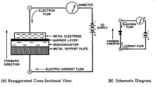
Fig. 2-3. The Rectifier Junction Showing Proportion of Free Electrons In Metal
Electrode and In the Semiconductor. (A) Exaggerated Cross-Sectional View. (B)
Schematic Diagram.
When the two dissimilar conductors are connected to a source of direct current electricity, as shown in Fig. 2-3, the opposite polarities set up an electric field across the barrier layer; as this barrier layer is so very thin, a nominally small potential difference across it will result in a steep potential gradient. If the metal electrode is connected to the negative terminal of the direct current source and the semiconductor is connected by way to the support plate to the positive terminal as in Fig. 2-3A, the free negative electrons in the metal electrode are accelerated to a sufficient velocity to pass through the barrier layer and the inter-crystalline space of the semiconductor to the metal support plate with the result that this flow of electrons constitutes an electric current flow in the forward direction.
The characteristic curves of the rectifier cell to be discussed later support this theory in that the rectifier junction has high resistance in the forward direction for very low applied voltage; as the applied potential is increased, more free electrons from the metal electrode are accelerated and reach the support plate resulting in greater current flow through the rectifier.
When the applied polarity to the rectifying junction is reversed, that is, the metal electrode is polarized positive and the semiconductor polarized negative, the same action takes place but a new condition exists. Now the semiconductor has to supply the free electrons and, as it is a sparse source of free electrons because it is a poor conductor, few electrons will be able to penetrate the barrier layer and make contact with the metal or front electrode; hence, the resulting current flow is much smaller. This current flow in the reverse direct ion is called reverse current or leakage current.
The function of the metal support plate is to afford a conducting support for the semiconductor layer and provide one terminal of the rectifying junction. It is essential that no barrier layer be formed between the semiconductor and its support plate for the type of rectifying junction shown in Fig. 2-3A; should this occur, counter rectification would take place and the rectifying properties of the cell would be reduced or nullified. For equal voltages in both directions across the rectifying junction, the forward current is several thousand times greater than the reverse current.
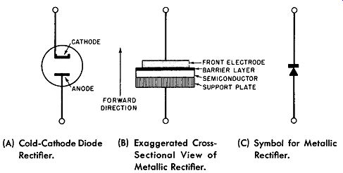
Fig. 2-4. Comparison of Metallic Rectifier Cell to Cold-Cathode Rectifier.
(A) Cold-Cathode Diode (B) Exaggerated Cross- (C) Symbol for Metallic Rectifier. Rectifier. Sectional View of Metallic Rectifier.
The rectifier junction may be compared to a cold cathode electronic tube as shown in Fig. 2-4, in which the front-metal electrode forms the cathode; the metal support plate, the anode; and the semiconductor and barrier layer, the insulator between the two electrodes. The function of the semiconductor is chiefly that of a medium between the anode and the barrier layer to enable the accelerating positive potential to be in extremely close proximity to the cathode without simultaneously resulting in a high reverse current.
From this assumption the thickness of the semiconductor and its crystalline structure should have considerable influence on the performance of the rectifying junction; this is verified in practice. The forward resistance of the rectifier cell is a function of the semiconductor, the barrier layer and the front electrode; the reverse resistance is the function of the barrier layer.
It can be inferred from the above theoretical explanation, and this is borne out in practice, that the barrier layer is the most important part of the rectifying junction as to its performance and stability.
Volt-Ampere Relationship of the Junction
The unidirectional conducting property of the metallic rectifier is best shown graphically by its volt-ampere curve--the graph which shows the relationship between the applied voltage to the junction and the resultant current flow. This type of curve may be obtained experimentally by the circuit given in Fig. 2-5.
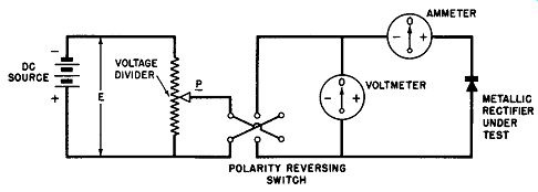
Fig. 2-5. Test Circuit for Rectifier Junction.
Here a source of direct current power energizes a voltage divider; any desired value of DC voltage from zero to E may be obtained by adjusting the position of the slider, P. This adjustable voltage is then applied to a polarity reversing switch the output of which is applied to the metallic rectifier junction under test. An ammeter in series measures the current flow and a voltmeter across the circuit indicates the magnitude and the polarity of the applied voltage.
The characteristic of the rectifier for one polarity is determined by maintaining the polarity of the applied voltage fixed and increasing the applied voltage by successive adjustments of the slider P and noting the current flow at each value of applied voltage. Reversing the polarity switch and repeating the process gives the opposite polarity performance. The experimental data thus obtained can be plotted in the form of a curve.
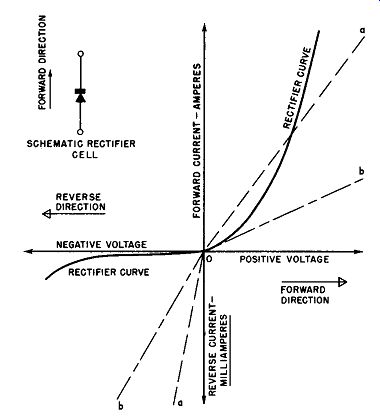
Fig. 2-6. Volt-Ampere Curve for Generalized Me tame Rectifier Junction.
This curve depicts the voltage-current characteristic of the metallic rectifier cell. Such a characteristic curve is shown in Fig. 2-6; from this type of information it becomes possible to more quickly determine the operating properties of the rectifier for circuit applications.
Since the reverse current is so much smaller than the forward current, the current scale of the graph is plotted as amperes per unit area above and in milliamperes per same unit area below the voltage axis. This is common practice in metal rectifier graphics. Moreover, for reference and comparison two other volt-ampere curves A and B are also drawn in Fig. 2-6. These are characteristic curves for pure resistors, curve A for a moderate value of resistance; curve B for a higher ohmic resistance. The break in the linear resistor curves as they pass through O is due to the non symmetrical current axis described in the foregoing.
The non-linear properties of the rectifier junction is clearly seen when its curve is compared with that of the pure resistors. As the applied voltage is increased in the forward direction, the current through the rectifier junction increases quite slowly at first; then, the current rate becomes quite rapid with applied voltage approaching a linear characteristic for its larger values.
In the reverse direction the applied voltage must be increased to large values before even small amounts of current flow are detected.
In the forward direction the maximum applied voltage (voltage drop across the cell) is limited by the maximum rated current for the particular rectifier. This rated current is based mainly upon the effective rectifier cell area and the permissible temperature at which the rectifying junction operates.
Typical forward direction voltages for commercial cells of the types to be described are of the order of a fraction of a volt to a few volts.
In the reverse direction the maximum applied voltage across the rectifying junction is limited by the breakdown across the barrier layer when the potential gradient becomes too great. When a breakdown occurs the cell junction no longer has the rectifying properties and symmetrical current flow results. Some of the commercial rectifying junctions to be described possess self-healing rectifying junctions against voltage breakdown troubles provided the junction is not unduly and prolongly abused. For power rectifier type junctions the maximum reverse direction voltage varies from 5 to 32 volts rms per cell, depending upon the type of junction. Small current rectifiers have been made to withstand 50 or more volts per cell in the reverse direction.
The forward or positive polarity values correspond to the low resistance direction of the rectifier, while the reverse or negative polarity values represent the high resistance direction. The curve described previously clearly shows that the metallic rectifier performs substantially as a unidirectional valve readily permitting current flow in the one direction while resisting current flow in the opposite direction. This is the function of a rectifier cell. The ideal rectifier would have zero resistance in the forward direction and infinite resistance in the opposite direction. The volt-ampere curve of Fig. 2-6 illustrates that the commercial rectifier nearly approaches this ideal rectifier. This type of graph is also called the static characteristic of the rectifying junction because the applied voltages and the resulting current flows are direct, not alternating.
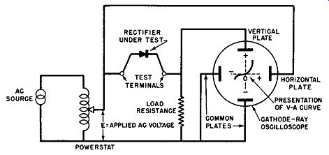
Fig. 2-7. Circuit for Testing Dynamic Volt-Ampere Properties of Metallic Rectifier
Cells.
Often it is desirable to obtain the voltage-current curve simultaneously with changes in circuit conditions; of course, this would be impossible with laborious data seeking and plotting technique described before. By using a direct-coupled cathode-ray oscilloscope with suitable amplification in both the vertical and horizontal axes, an automatic and instantaneous presentation of the voltage-current characteristic of any rectifier junction may be had for any desired circuit condition.
This type of presentation is called the dynamic characteristic of the rectifying junction. The simplified circuit for obtaining this information is given in Fig. 2-7. This arrangement is very useful for production or receiving inspection. The nominal curve of a rectifier with desired performance can be traced upon a transparent sheet and placed before the oscilloscope screen. The characteristics of the unknown rectifier cells can be quickly compared with the desired standard-making out of the arrangement a "go", "no-go" inspection de vice for testing newly produced rectifier cells from the assembly line or newly received rectifiers from a vender.
Moreover, it may be desirable to see the changes in performance of a given rectifier for varying ambient conditions such as temperature, humidity, or varying applied frequency.
All this is readily possible with the dynamic type of characteristic presentation.
Voltage-Resistance Properties of the Junction
The voltage-resistance properties of a generalized metallic rectifier junction of unit area is shown in Fig. 2-8. The graph shows the resistance of the junction or rectifier cell in the forward and reverse direction as a function of applied voltage of positive and negative polarity.
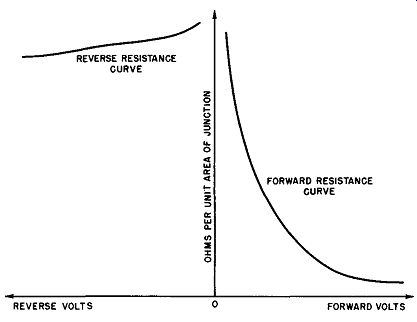
Fig. 2-8. Static Voltage-Resistance Properties of a Generalized Rectifier
Junction of Unit Area Operated Within Its Voltage Limits.
This curve may be obtained for any junction by using the experimental arrangement of Fig. 1-7 where a Wheatstone bridge method of resistance measurement is shown. The voltage applied to the bridge is varied in discrete steps and the corresponding resistance measurements made. The actual applied voltage to the junction may be obtained by computation or by means of a DC vacuum-tube voltmeter.
The actual voltage-resistance curve for any specific rectifier junction may differ from the one shown in Fig. 2-8 but in general the following comments will apply. As the applied voltage is increased in the forward direction the resistance decreases very quickly at first and then gradually approaches a constant value. In the reverse direction the resistance also decreases with applied voltage of opposite polarity but the rate is very small within the limits of the rated cell voltage.
It can be inferred from Fig. 2-7 and 2-8 that the resistance of a metallic rectifier junction is not constant with respect to current flow and in the forward direction decreases as the current increases. See Fig. 2-9.
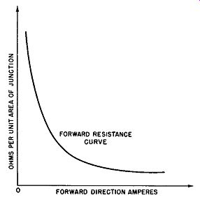
Fig. 2-9. Forward Resistance Versus Forward Current for Generalized Rectifier.
The non-linear resistance properties of the rectifying junction in the forward direction may be employed in a number of interesting applications, an example is voltage regulators in direct current circuits.
Other Properties of the Metallic Rectifier Cell
Other properties of the metallic rectifier cell such as temperature effects, current and voltage rating, efficiency, forming, speed of operation, and the like are too difficult to generalize since they differ so radically for the three types of rectifiers to be discussed. Hence, these and other effects will be reserved for later discussion under the specific types.