AMAZON multi-meters discounts AMAZON oscilloscope discounts
Introduction
Up to this point in this guide the reader has become acquainted with the need for an effective device for changing alternating current electricity into direct current electricity and has studied in some detail the elements, the properties, and the electrical characteristics of three types of metallic rectifiers; namely, the copper-oxide, the selenium, and the magnesium-copper sulfide.
In a very few metallic rectifier applications the type of rectifier which is used is not of any particular consequence, but in general some property of one particular type makes it especially suitable for a given application. How then is one to determine which rectifier type to use in a specific application? A comparison of the properties of the three types will perhaps reveal the advantages and limitations of the rectifiers under discussion. Such is the purpose of this section.
Comparison of Volt-Ampere Characteristics
The reader has learned from past sections of this guide that the volt-ampere characteristic of a metallic rectifier is a valuable and quick way to evaluate its potential merits. What we are principally looking for in these characteristics in the forward direction is the required forward voltage drop across the cell for the permitted forward current flow, and the amount of current flow in amperes per square inch. In the reverse direction we are interested in the maximum value of reverse applied voltage before breakdown of the barrier layer or before substantial leakage current results, and the magnitude of the leakage current. The reverse voltage of the rectifier cell gives us an idea as to the potential voltage rating permitted for the cell. Of course, the comparison characteristics should be at the same temperature for we have learned that the characteristics under study are not independent of temperature.
In Fig. 7-1 is drawn a comparison graph of the volt ampere characteristics of the three types of metallic rectifiers--drawn to a common volt-ampere scale and representative for each type at 20 degrees Celsius. The magnesium-copper sulfide curve was a little awkward to draw since the current response is so much greater than for the other two types for both directions of current flow. Moreover, we learned in Section 6, that the static or DC characteristics of this type rectifier is highly variable and that the hysteresis nature of the volt-ampere property produces a closed loop curve for both directions of current flow. The magnitude of the magnesium copper sulfide rectifier curve in the forward direction is of the order of 25 to 50 amperes per square inch; the curve runs off the graph. The forward current values shown in this graph are for comparison purposes only--not operating values; at the values shown the rectifier cells would overheat unless forced cooling were employed.
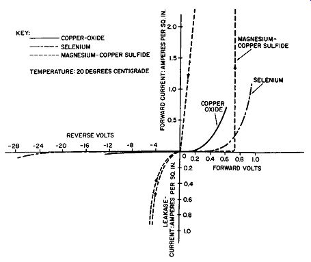
Fig. 7-1. A Comparison of the Volt-Ampere Characteristics of the Three Types
of Rectifiers.
On a comparative basis it is easy to see from Fig. 7-1 that the copper-oxide rectifier has no forward threshold voltage, while the threshold voltage for the selenium is about 0.2 volt and that for the magnesium-copper sulfide is a pronounced 0. 7 to 0.8 volt. Moreover, the forward current for the copper-oxide and the selenium rectifiers is of the order of one ampere per square inch compared to the 25 to 50 amperes per square inch for the magnesium-copper sulfide rectifier. Additionally, the forward voltage drop at a given current density is approximately one-half as great for the copper-oxide rectifier as for the selenium rectifier.
In the reverse or leakage current direction one can see from Fig. 7-1 that the applied voltage to the rectifiers must be limited to about 3 1/2 volts for the magnesium-copper sulfide, 8 volts for the copper-oxide, and 26 volts for the selenium type. At these values of reverse applied voltage the leakage current for the copper-oxide and the selenium rectifiers is about 2 to 4 milliamperes per square inch, while for the magnesium-copper sulfide it is an excessive 1 ampere per square inch.
Comparison of the Voltage-Temperature Characteristics
The curves of Fig. 7-2 illustrate the variation of the for ward voltage drop across the rectifier cell as a function of temperature. It will be noted that although a greater forward voltage drop is required, namely 0.8 to 0.9 volt, this drop· is maintained practically constant in the case of the magnesium-copper sulfide cell.
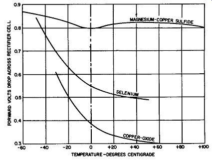
Fig. 7-2. Forward Voltage-Temperature Characteristics of Rectifier Types.
The selenium and copper-oxide rectifier cells shows a large increase in the forward voltage drop across the cell as the temperature is decreased.
The behavior of the three rectifiers in the reverse direction is somewhat more difficult to give graphically. The over-all response of the rectifier is dependent upon this as well as upon the current density of the cells, but, in general, the over-all response is similar to Fig. 7-2--the magnesium copper sulfide type being less dependent upon the temperature and over a greater temperature range. Refer to Fig. 6-14 as further illustration of this statement.
Comparison of the Voltage Ratings
In line with the discussions in previous sections of this guide, the voltage rating of the three types of rectifier cells at their rated temperatures and current densities is as follows:
Type
Magnesium-copper sulfide Copper-oxide Selenium Volts per Cell.
3.5 8.0 26.0
This information is given pictorially in Fig. 7-3 and represents a rectifier type selection chart on the basis of voltage rating.
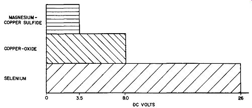
Fig. 7-3. Selection Chart on Basis of Expected DC Volts Required.
For example, if the proposed application calls for a rectified output of 20 volts, the economical cell type to select is the selenium, for, in a half-wave circuit but one such cell is required; in a full-wave bridge circuit four such cells are required. If the copper-oxide type cell is selected, the half-wave circuit re-quires 3 cells whereas the full-wave bridge requires 12 cells.
Thus, on the basis that the more economical and efficient rectifier stack uses the least rectifier cells, the selenium type is the choice and the chart of Fig. 7-3 makes possible an easy selection of the rectifier type on the basis of voltage requirements alone. Other considerations may alter the selection.
For economical selection on the basis of volts output alone, up to 3.5 volts, the choice of the three types of rectifiers is optional; from 3.5 to 8 volts, the magnesium-copper sulfide drops out and the selection is between the copper-oxide or selenium; beyond 8 volts the selenium is the one to use. If the required rectified voltage is greater than 26 volts, two or more selenium rectifier cells in series are required. (Refer to Section 3.)
Selection On the Basis of Current Ratings
For the convection cooled rectifier cell at an ambient temperature of 35 to 40 degrees Celsius, the copper-oxide rectifier cell is rated at 1/10 ampere per square inch, the selenium rectifier cell is rated at 1/ 4 ampere per square inch, and the magnesium-copper sulfide rectifier cell is rated at 15 amperes per square inch. This information is pictured graphically in Fig. 7-4 which forms a convenient rectifier type selection chart on the basis of current rating alone. We have learned that physically these rectifier cells are limited to certain dimensions (refer to chart on page 142 of this section). Thus to achieve large current ratings for the copper-oxide or selenium rectifier types requires paralleling rectifier stacks.
On the basis of current requirements alone Fig. 7-4 makes for easy selection of the rectifier type.
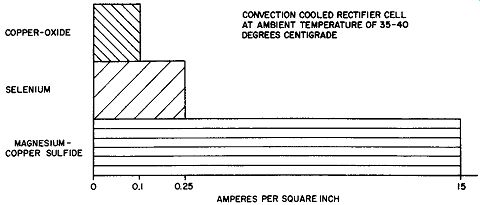
Fig. 7-4. Comparison of Rectifier Types on Basis of Ampere Per Square Inch
Current Flow Permissible.
Comparison of Efficiency
The curves of Fig. 7-5 make possible the comparison of the efficiency of the three types of rectifiers. These curves are based upon using the rectifiers in a three-phase circuit which feeds a resistive load. On the basis of efficiency alone then, the selenium type rectifier is best with the copper-oxide rectifier a close second.
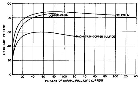
Fig. 7-5. Efficiency Curves for the Three Types of Rectifiers-Three-Phase
Circuit, Resistive Load.
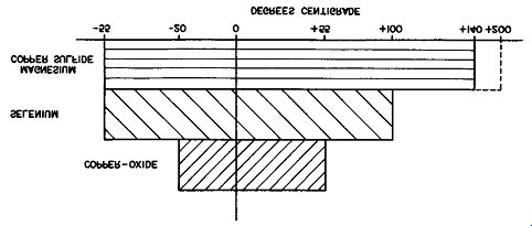
Comparison of Operating Temperatures
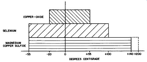
Fig. 7-6. Operating Temperature Range for the Three Rectifier Types.
Fig. 7-6 presents a metallic rectifier comparison chart on the basis of operating temperatures alone. It confirms our past discussion that the magnesium-copper sulfide rectifier type covers the widest temperature ranges and is the only rectifier which works satisfactorily above 125 degrees Celsius to over 200 degrees Celsius.
The selenium rectifier has the next best temperature range, while the temperature range of the copper-oxide type rectifier, by comparison with the other two types, is quite restricted, indeed.
Actually, the temperature range over which satisfactory operation is secured must be qualified by the desired life expectancy. Thus, with some reduction of life, selenium power rectifiers may operate up to 125 degrees Celsius while the magnesium-copper sulfide rectifiers will operate in excess of 500 hours in temperatures of 200 degrees Celsius or over.
Temperatures below zero degrees Celsius limit the electrical properties of all three types of metallic rectifiers and all three types can be operated for a short time at temperatures as low as minus 70 degrees Celsius.
The Comparison Chart
Many of the properties of the three types of rectifiers are not easily compared graphically because of dependency upon other factors. Moreover, the best solution for an application is not usually dependent upon a single factor such as efficiency, voltage rating, current rating, etc. It then becomes necessary to present a chart with the pertinent properties listed in such a fashion as to permit comparison. This chart is given on page 142; knowing the operating conditions of an application this chart should ease the selection of the rectifier type.
Conclusions
The conclusions which one can draw from the preceding comparison discussion may be briefly summarized as follows:
1. Where the application calls for heavy current, moderate voltage output up to 50 to 60 volts and/ or operating temperatures over 125 degrees Celsius, consider the magnesium-copper sulfide type of rectifier.
2. Where the application calls for moderate to low currents, high stability, and reproducible characteristics, such as for instrument or control purposes, use the copper oxide type of rectifier.
3. Where the application calls for high efficiency, moderate to heavy current, rectified voltages greater than 50 to 60 volts, use the selenium rectifier.
------- METALLIC RECTIFIER COMPARISON CHART