AMAZON multi-meters discounts AMAZON oscilloscope discounts
Introduction
The next type of metallic rectifier to be discussed in this guide is the magnesium-copper sulfide rectifier. This type in conjunction with the other two types ( copper-oxide and selenium) already discussed have, up to the present time, serviced the bulk of the rectifier applications in the United States.
The magnesium-copper sulfide rectifier is not as widely used as the copper-oxide or the selenium rectifiers already described, but it has several important properties which has kept it in demand. First of all, it is the only commercial rectifier that will operate successfully above 200 degrees Celsius. The second desirable property is its current rating.
As an example: for design purposes selenium and copper-oxide rectifiers are considered to have a current of less than one ampere per square inch, while the magnesium-copper sulfide rectifier is rated at 35 amperes per square inch.
It appears from a study of the patent literature that the magnesium-copper sulfide rectifier also had an early beginning. It would be extremely interesting to determine whom to credit with the invention of the first metallic rectifier and to learn the rectifier type. It seems that the copper-oxide and the magnesium-copper sulfide rectifiers were developed concurrently. For example, United States Patents numbered 1,649,741, 1,649,742, 1,649,743, 1,649,744, 1,723,525, and 1,751,359, all issued to Samuel Ruben, clearly outline the magnesium-copper sulfide type of rectifier. The first patent of the above list has an application file date of September 27, 1924, whereas the last number has an application file date of August 20, 1925.
From a study of the trade literature it appears that Samuel Ruben's magnesium-copper sulfide rectifier patents are implemented chiefly by P.R. Mallory Company of Indianapolis, Indiana, for this is the principal source of this type of rectifier. The second, and only other source for the magnesium-copper sulfide rectifiers is Electronic Rectifiers, Inc., also of Indianapolis.
Production
The principal components of a magnesium-copper sulfide rectifier cell, before electroforming, are a magnesium or magnesium alloy plate or disc having a slightly oxidized active surface and a cupric sulfide plate or disc. Rectification can be secured by placing these two plates in contact with each other; however, stable and dependable rectification characteristics demand bonding between the two electrodes which can be obtained by the electroforming process to be described.
Magnesium as the base plate metal has the advantage of good electrical conductivity as an electrode and it helps form a barrier layer of limited thickness. In manufacturing the magnesium-copper sulfide cells, the magnesium is processed in strip form and then the washers or plates are punched from this strip and prepared for assembly with the copper sulfide elements.
The copper sulfide as the front electrode also possesses the advantage of good electrical conductivity; it also has a low temperature coefficient for its resistance and supplies one of the components for the formation of the barrier and semiconductor layers integral with the front and base electrodes.
The barrier and semiconductor layers are formed electrically by the interfacial reaction of the above two electrodes.
Thus, the actual physical materials which are required to produce the magnesium-copper sulfide cells are a pure magnesium disc or plate as the base metal and a pure and dense cupric sulfide disc for the front electrode.
Besides these physical requirements for the production of magnesium-copper sulfide cells, it is necessary that the magnesium disc or plate have on its active surface a very superficial layer of oxide; this is required so as to limit the initial electro-formation currents to small areas reducing the heating, electric arcing, and the electrical energy which would be required if the entire cell junction were formed simultaneously.
The superficial oxide film upon the active surface of the magnesium electrode may be produced electrochemically or may be formed by treating the magnesium with a chemical solution; the film should possess a voltage breakdown characteristic of a few volts (about 4 volts), the exact value being somewhat critical.
The cupric sulfide disc must also be chemically pure to produce a stable rectifier cell; moreover, since it must have a smooth surface to assure a good mechanical contacting area with the magnesium electrode for the electroforming operation, it must have great mechanical strength to withstand the grinding operation necessary to achieve this smooth surface.
Sulfide discs processed from pure copper are not satisfactory because they are too soft and fragile for the grinding operation. In commercial practice the copper sulfide element of the magnesium-copper sulfide rectifier cell is generally formed from a brass disc which possesses about 15% zinc.
This brass disc, which is to become the copper sulfide element of the rectifier cell, is treated with liquid sulfur which removes the zinc from the surface of the brass disc leaving on the outer surface of this disc pure cupric sulfide (CuS) and a center of zinc and copper sulfides. Another method used to produce the front electrode consists of exposing the copper or brass discs to sulfur vapor at about 400 degrees Celsius for various periods of time. By this treatment the copper is converted to either cupric sulfide, CuS, or cuprous sulfide, Cu2S. Front electrode washers obtained by the sulfiding process are very dense and mechanically strong; they lend themselves to the grinding operation necessary to provide a highly smooth and finished surface for contacting the magnesium element.
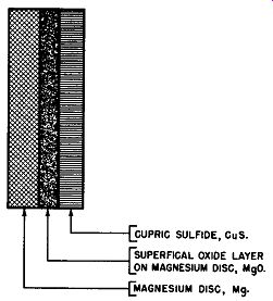
Fig. 6-1. Grossly Exaggerated Cross-Sectional View of Magnesium Disc In
Contact with Cupric Sulfide Electrode Previous to Electro-formation to Produce
Magnesium-Copper Sulfide Cell.
To electroform the magnesium-copper sulfide cell, the magnesium and the cupric sulfide electrodes are placed together, either as cells in special forming fixtures or in the ultimate rectifier stack. Fig. 6-1 shows in cross-sectional form the layout of the unformed magnesium-copper sulfide rectifier cell. It can be seen from this figure that the unformed rectifier cell comprises a disc of magnesium, Mg, with a superficial layer of magnesium oxide, MgO, on its active surface adjacent to which is placed the cupric sulfide disc, CuS. Then an alternating voltage is applied to the cell. The peak value of this alternating voltage exceeds the breakdown voltage of the superficial oxide film on the active surface of the magnesium electrode (about 4 volts) and causes a current to flow through the weakest part of the oxide film.
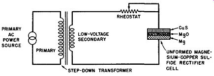
Fig. 6-2. Electrical Circuit Suitable for Electroforming the Magnesium-Copper
Sulfide Discs Into a Magnesium-Copper Sulfide Cell.
A simple circuit suitable for this process is shown in Fig. 6-2. Here, a primary source of AC electrical energy is reduced in voltage by means of the step-down transformer shown. The secondary of this transformer supplies the unformed magnesium-copper sulfide cell in series with a current controlling rheostat. This rheostat is adjusted so that the forming current is limited to about 2.5 amperes per square inch of the active cell area.
In each half cycle of the applied AC voltage when the magnesium disc is polarized positive and the cupric sulfide disc negative, that is, when the cell's reverse voltage exceeds the breakdown voltage of the magnesium oxide film, electro formation of the junction takes place. This electro-formation continues until all of the magnesium surface of the cell has been converted into magnesium sulfide.
When the electroforming process is completed, the magnesium-copper sulfide cell has a cross-sectional layout as shown in Fig. 6-3. It will be observed that the active surface of the metal base electrode, the magnesium disc, is covered with a layer of magnesium sulfide, MgS, while the cupric sulfide surface layer of the copper sulfide electrode adjacent to the magnesium disc is converted into cuprous sulfide, Cu2S, and bonded to the magnesium sulfide film which constitutes the rectifier cell's barrier layer. The cuprous sulfide layer is the rectifier cell's semiconductor layer.
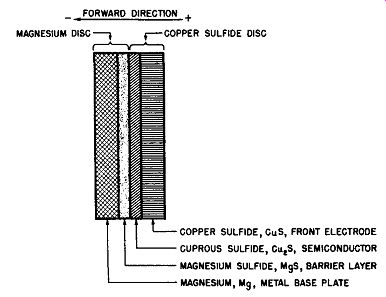
Fig. 6-3. Exaggerated Cross-Sectional View of Magnesium-Copper Sulfide Cell
After Electroforming Operation.
The normal operating range of the magnesium-copper sulfide rectifier cell is 3.5 volts and the forming voltage is of the order of 4 to 6 volts. A forming voltage greater than that required to produce the barrier film results in sparking due to the breakdown of the insulating layer of magnesium sulfide and the decomposition of the cuprous sulfide into copper or copper-oxide. This copper-oxide in contact with the magnesium increases the forward resistance and decreases the re verse resistance which increases the leakage current.
The inventor of the magnesium-copper sulfide rectifier, Samuel Ruben, has a concise explanation for the process of the electro-formation and his explanation, derived from the "Transactions of the Electrochemical Society", Vol. 87, 1945, page 248, is given below.
"The action that occurs in the process of formation following the initial puncture of the MgO film may be explained as follows: When the cupric sulfide electrode is the negative terminal in the forming circuit, the current flow to it from the contacting magnesium electrode through the localized point area will reach a value where there will be an insufficient number of electrons available from the surface of the cupric sulfide. At this point there is a rise in potential at the sulfide surface, which at a sufficient value causes disruption of the cupric sulfide into cuprous sulfide and a free sulfur ion. Under the influence of the electric field, the sulfur ion combines with the magnesium, forming a polarized layer of magnesium sulfide. As soon as the blocking effect of the reacted area exceeds the breakdown voltage of the superficial MgO layer, adjacent areas puncture and form until the entire junction area is uniformly reacted.
"When the layer of MgS, which integrally bonds the electrodes, is built up to a value at which the potential gradient becomes distributed over it, instead of at the electrode inter face, the current decreases to a leakage value and no further increase of the barrier layer thickness occurs. If the potential were to be continuously increased to a point above the critical breakdown voltage of the magnesium sulfide layer, instead of increasing the thickness of the layer, continuous sparking by disruption and oxidation of the electrode surfaces would occur." From this description it can be understood that the forming operation is somewhat critical and must be done under carefully controlled conditions of cell mechanical pressure, temperature, applied voltage, and current.
At the conclusion of the electroforming process the magnesium and the copper sulfide elements are cemented firmly together by the thin film of magnesium sulfide which is formed from the original elements of the cell under the influence of temperature and the electric current.
Cells electroformed in this manner have the property of asymmetric current conductivity with the electric current flowing more readily from the copper sulfide to the magnesium than in the reverse direction. The thin film of magnesium sulfide serves as the barrier layer of the rectifier cell, the magnesium element serves as the metal base electrode, and the copper sulfide element serves both as a source of sulfur to contribute to the production of the barrier and semiconductor layers and as a front electrode.
Fig. 6-4 is a cross-sectional and front view of a magnesium-copper sulfide rectifier cell. The interfacial details are not repeated--these can be studied in Fig. 6-3. The dimensions which are given are representative of a typical commercial cell rated at 100 amperes maximum DC, when it is used in a single-phase, full-wave bridge circuit. This maximum current rating applies when forced draft cooling employing an air flow of 500 cubic feet per minute is used. For natural convection cooling this cell is rated at 15 to 16 amperes DC. The effective rectifying area of the cell shown is about 2.65 square inches and the thickness dimension given does not include the non-polarizing disc.
The central hole is used for mounting purposes when the cell is assembled into rectifier stacks. The base plate is magnesium or magnesium alloy and in commercial practice it has been found that its thickness may be varied appreciably with out altering the rectifying properties of the cell to any great extent.
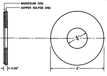
Fig. 6-4. Cross-Sectional and Front View of a Typical Magnesium-Copper Sulfide
Rectifier Cell With out Non-Polarizing Disc.
The front electrode of the magnesium-copper sulfide rectifier cell is the copper sulfide disc; however, to maintain the original operating characteristics of the rectifier cell after the electroforming process, it is necessary to employ a counter electrode or non-polarizing contact to engage the inactive surface of the sulfide electrode. The reason for this is that all common metals which might be used to contact the sulfide electrode will sulfide in time under the influence of the cell voltage drop and the chemical effects. Sulfide formation on the surface of the copper sulfide adjacent to the contacting electrode will increase the internal resistance of the rectifier cell and cause polarization which results in a continuous de crease in efficiency. The use of a thin carbonized nickel or iron disc as a counter electrode or non-polarizing electrode eliminates this difficulty and maintains the desired low resistance contact to the copper sulfide disc. Often the front electrical connection to the copper sulfide surface is achieved by contact with the nickel plated surfaces of spacer washers or radiator and terminal plates of the rectifier stack.
Another condition which is required to maintain the original operating characteristics of the magnesium-copper sulfide cell is the exclusion of moisture. Although the cell junction is bonded and electrically stable by virtue of the electroforming process, it is still subject to adverse reactions in the presence of moisture. The combination of MgS and water yields magnesium oxide and hydrogen sulfide which causes progressive blocking off of the effective rectification area by the production of a magnesium oxide layer. This moisture effect is eliminated by the application of several layers of waterproof and heat-resisting varnishes to the entire surface of the rectifier unit and then thoroughly baking the finish.
The forward current flow in the magnesium-copper sulfide cell is in a direction normal to the plane of the cell disc and its magnitude is dependent upon the effective rectifying area of the cell and upon the applied voltage in a manner to be described later in this Section.
In commercial practice the magnesium-copper sulfide cell is generally made in disc form and in diameters which range from 1/2 to 2 inches.
Construction In the practical application of the magnesium-copper sulfide rectifier cells, it is necessary to assemble these cells in the required number and sequence into rectifier stacks in the manner discussed in Section 3.
Actually, in the case of the magnesium-copper sulfide rectifiers, the cells may be electroformed either before or after being assembled into stacks. The rectifier stacks are assembled under pressure of about 2500 pounds per square inch upon threaded studs or bolts and consist of the required number of cells and their associated heat dissipating and terminal plates, spacer washers, and non-polarizing discs. These non-polarizing discs are inert conductors, such as carbonized materials or nickel plated spacer washers or radiator plates and terminal plates; the job intended for the non-polarizing discs is to pre vent counter rectification at the outer surface of the copper sulfide disc which would decrease the rectifying properties of the cell.
The radiator plates besides providing electrical connection to the cells facilitate cooling of the cells both for convection or forced draft cooling mode of operation.
The necessary components to fabricate a commercial magnesium-copper sulfide rectifier stack are shown in Fig. 6-5. These components are required so as to assemble the individual rectifier cells in series, parallel, or series-parallel arrangements to provide the voltage and current specifications of the stack. As each rectifier is rated at about 3. 5 volts rms, it is necessary to assemble the required number of cells upon an insulated and threaded stud or bolt passing through the hole in the center of the cell. The rectifier stack also requires radiator plates, terminal plates, non-polarizing discs or the optional nickel-plated spacer washers, insulators, end washers, spring washers, and assembly nuts.
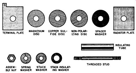
Fig. 6-5. Elements of the Magnesium-Copper Sulfide Rectifier Stack.
In practice, the length of the rectifier stack is limited to about 40 cells--about 10 to 12 inches long. The cells re quire the processing treatment already described which limits their diameters from a minimum of 1/2 inch to a maximum of 2 inches. Thus, heavy current rectifiers require one or more of the large size cells in parallel and forced draft cooling.
Paralleling of the cells is frequently accomplished on common radiating and terminal plates; or, if desired, separate stack assemblies may be paralleled externally.
Fig. 6-6 illustrates a cutaway view of a single-phase, full-wave bridge rectifier using two magnesium-copper sulfide rectifier cells per leg.
A typical single-phase, full-wave magnesium-copper sulfide bridge rectifier employing the 2 inch diameter cells and operating under forced draft cooling of 500 cubic feet per minute, has the following approximate specifications:
Maximum AC volts rms, no load Maximum AC volts rms, loaded DC volts at maximum resistive load 10.5 9.75 4.8
Maximum DC current into resistive load, amperes Maximum DC current into resistive load, convection cooling, amperes Number of cells per leg of bridge Total number of cells in rectifier stack 100 16 3 12 Overall Dimension of stack Weight of stack 4x5x7 inches 6 1/2 pounds
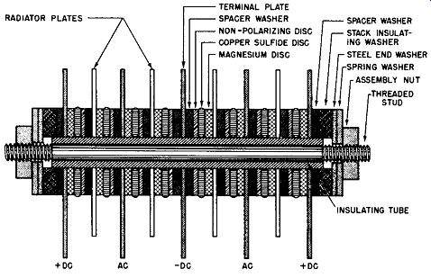
Fig. 6-6. Cutaway View of a Magnesium-Copper Sulfide Bridge Rectifier, Single-Phase,
Full-Wave.
As can be seen from Fig. 6-6 the central terminal of the rectifier stack is the negative output connection whereas the two end terminal plates are the positive terminals of the DC output; thus, it is necessary to strap these two terminal plates together to complete the bridge connections. The situation is clarified in schematic form in Fig. 6-7. Fig. 6-7A shows the simplified schematic for the magnesium-copper sulfide rectifier cell, identifying both the forward direction polarity and the rectification polarity as previously defined in this guide.
Fig. 6-7B shows the magnesium-copper sulfide stack circuit as represented by the physical layout of Fig. 6-6 except that for simplicity only one cell per leg is displayed; and the bridge circuit is completed by strapping the two DC terminals together in Fig. 6-7C. See the dotted line connections.
Of course, if it is desirable, there is nothing to prevent the magnesium-copper sulfide cells being so placed upon the stack assembly that the central terminal is positive and the outer terminals, which must be strapped together to complete the rectifier bridge, are negative.
(A) Magnesium-Copper Sulfide Rectifier Cell.
(B) Single-Phase, Full-Wave Bridge Rectifier Without Positive Terminals Strapped Together.
(C) Single-Phase, Full-Wave, Bridge Rectifier With Positive Terminals Strapped Together by Dotted Line.
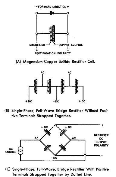
Fig. 6-7. Schematics of Single-Phase, Full-Wave Magnesium-Copper Sulfide
Rectifier.
Elements of the Magnesium-Copper Sulfide Rectifier Cell
Section 2, of this guide defined the generalized metallic rectifier cell as comprising four elements listed below:
1. Metal base or support plate.
2. Semiconductor layer.
3. Barrier layer.
4. Front or counter electrode.
This description of the generalized metallic rectifier cell also applies to the magnesium-copper sulfide rectifier cell discussed in this section. By reference to Fig. 6-3, which illustrates the magnesium-copper sulfide rectifier cell after it has been electroformed, it can be seen that the metal base plate here is the magnesium or magnesium alloy disc or plate.
The semiconductor layer is the cuprous sulfide film on the active surface of the copper sulfide disc, placed there as a result of the electroforming operation previously described.
The barrier layer is the magnesium sulfide film on the active surface of the magnesium electrode, also placed there by the electroforming process. Moreover, this barrier layer bonds or cements the magnesium and copper sulfide elements together upon the completion of the electroforming process. The front electrode is the copper sulfide disc and, to prevent sulfide action between it and the contacting terminal electrode, a contacting electrode of carbonized iron or a nickel plated washer is used which serves as the electrical connection to the inactive surface of the copper sulfide and in addition prevents counter rectification at this surface. Thus, electrical connection to the rectifier cell is obtained by one terminal to the magnesium plate and the other terminal to the carbonized disc which makes electrical contact to the surface of the cuprous sulfide, semiconductor, through the low-resistance copper sulfide.
Easy flow of electric current occurs when the magnesium is made negative with respect to the copper sulfide. This is the forward direction of the magnesium-copper sulfide rectifier cell and follows the general rule which defines the forward direction as that resulting from the potential difference being directed from the semiconductor (cuprous sulfide) to the adjacent metal electrode (magnesium) across the barrier layer (magnesium sulfide). An exaggerated cross-sectional view of the magnesium-copper sulfide cell is shown in Fig. 6-8A. The forward direction is also shown. Although from Fig. 6-8A it would appear that the magnesium-copper sulfide rectifier cell has five elements, the combination of the copper sulfide disc and the carbonized washer may be considered as the front elect rode, since the only purpose for the carbonized washer is to prevent sulfiding and a gradual deterioration of the rectifier properties.
In Fig. 6-8B the electrical symbol for this rectifier cell is given. The arrow points towards the forward direction; however, when the cell is used as a rectifier, the rectification polarity is as shown here. (Refer to Section 3.)
(A) Exaggerated Cross-Sectional View of Rectifier Cell.
(B) Schematic Diagram Showing Rectification Polarity.
(C) Exaggerated Cutaway View of Half-Wave Rectifier With Rectification Polarity Identified.
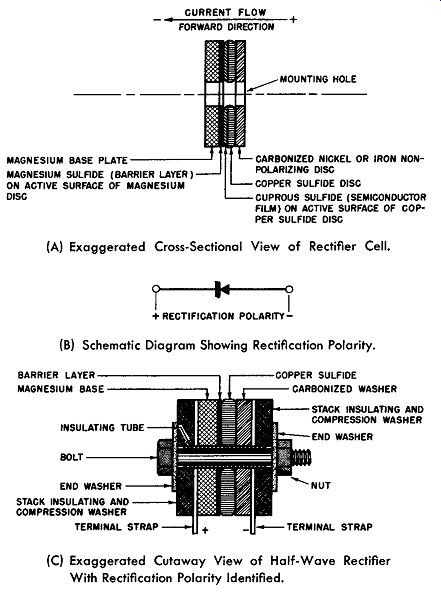
Fig. 6-8. The Magnesium-Copper Sulfide Rectifier.
In Fig. 6-8C a sketch is given to show how the magnesium-copper sulfide rectifier cell may be assembled into a practical half-wave rectifier. Radiator plates are omitted for simplicity and are not needed for low-current capacity stacks.
Volt-Ampere Characteristics
Previous sections have stressed the importance of the volt-ampere characteristics of rectifier cells. It also has been stated that two methods are available for obtaining this information--the DC or static characteristics technique and the AC or dynamic characteristics technique. For details of these two systems of measurement refer to Section 2.
Inconsistent results are obtained in an effort to determine the volt-ampere characteristics of the magnesium copper sulfide rectifier cell by the DC or static characteristics method because of the interrelationship of time and internal temperature with the primary variables of voltage and current.
However, the dynamic or AC characteristics at power line frequencies (preferably at 60 cycles per second) produce a more accurate indication of the operating relationships as they actually exist during rectification. Moreover, these dynamic characteristics are stable and reproducible, showing insignificant change with time or mean temperature.
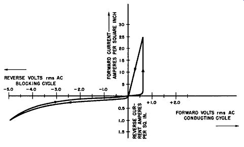
Fig. 6-9. Dynamic Volt-Ampere Characteristics of a Typical Magnesium-Copper
Sulfide Rectifier Cell.
Fig. 6-9 is a graphical presentation of the dynamic voltage-current characteristics of a typical magnesium-copper sulfide cell. Note that the forward or conducting voltage axis is plotted in increments of 1/2 volt; the reverse voltage axis is also plotted in 1/2 volt increments. To expand the rectifier characteristics, the forward current axis is plotted in 5 ampere increments, while the reverse or leakage current axis is plotted in 1/2 ampere increments.
From a study of these curves it will be seen that in creasing the forward voltage from zero results in an insignificant forward current until a critical voltage of about 0.6 volt rms is reached; after this initiating voltage is applied to the magnesium-copper sulfide rectifier cell the forward current rises abruptly to a relatively high value with little increase in the forward voltage. When the forward voltage is decreased from this critical conducting voltage value, the forward current decreases in approximately linear fashion.
On an alternating voltage excitation the conducting cycle of the magnesium-copper sulfide rectifier consists of a short period during which the current flow is negligible, until the applied voltage reaches about 0.8 volt peak value (0.6 x 1.4). From this point the current increases to a maximum value at practically constant voltage drop (note the vertical ascent of the current) and then decreases from the maximum value to zero at substantially constant resistance with reference to the value of resistance obtained at maximum current.
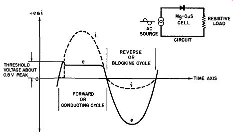
Fig. 6-10. Applied Voltage and Resulting Current Versus Time as Seen on
an Oscilloscope for a Magnesium-Copper Sulfide Rectifier Cell.
The lower curve in the section which displays the blocking cycle shows the leakage current as a function of the voltage as the applied reverse voltage is increased. The upper curve in this same section of the graph shows the leakage current as a function of reverse voltage as this voltage is reduced to zero. Both reverse voltage curves are non-linear. The arrows on the curves point in the direction which indicates the direction in which the applied voltage is increasing or decreasing.
This type of volt-ampere characteristic wherein the for ward and retrace properties are not the same, that is, there is a pronounced difference in forward and reverse conductance for increasing voltage as compared to decreasing voltage, is identified as a hysteresis effect.
Another way of exhibiting the voltage-ampere characteristics of the magnesium-copper sulfide rectifier cell is to display the functions of voltage and current against a common time base upon an oscilloscope screen. Such a presentation is given in Fig. 6-10. Here the voltage waveform which represents the voltage applied to the magnesium-copper sulfide cell is shown by the solid line curve. The resultant current through the rectifier cell, forward as well as leakage, is given by the dashed line curve. Again it can be clearly seen that the applied voltage in the forward direction must exceed a critical value of about 0.5 to 0.6 volt rms before current conduction initiates. Upon the initiation of the forward current it assumes large magnitudes with negligible forward voltage drop across the rectifier cell. For example, note the horizontal nature of the forward voltage waveform after conduction is initiated. In the reverse direction the magnesium-copper sulfide cell is different from the other two types of rectifiers studied previously in that appreciable reverse current flows, namely about 0.5 ampere per square inch for a reverse voltage across the cell of the order of 3 to 5 volts peak value.
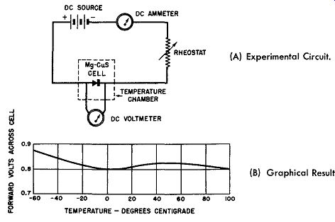
Fig. 6-11. Voltage-Temperature Characteristics of a Magnesium-Copper Sulfide
Cell.
(A) Experimental Circuit.
(B) Graphical Result.
Temperature Characteristics
The magnesium-copper sulfide rectifier cell may be operated over a wide range of temperatures with little change in internal resistance because its junction components have negligible resistance temperature coefficients.
The stability of the magnesium-copper sulfide rectifier cell from temperature effects may be experimentally demonstrated in a number of ways. For example, a constant current may be passed through the rectifier in the forward direction and the resulting forward voltage drop measured as the cell is exposed to a wide change in temperature. Any change in the forward voltage drop represents a change in the forward resistance with the changing temperature.
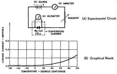
Fig. 6-12. Reverse Current-Temperature Characteristics of a Magnesium-Copper
Sulfide Cell. (A) Experimental Circuit. (B) Graphical Result.
The experimental set-up for this test is shown in Fig. 6-11A which shows a DC source of electricity; a rheostat by which to maintain the forward current constant, say at 5 amperes; a DC ammeter to indicate the value of the forward current; and a magnesium-copper sulfide rectifier cell all wired in series. Note that the DC voltage is applied to the cell in the forward direction. The cell is placed within a chamber in which the temperature can be varied over a wide range.
The experimental result from such a test is graphically presented in Fig. 6-11B. It can be easily seen that the change in forward resistance is negligible over the temperature range of -60 degrees to +100 degrees Celsius (212 degrees Fahrenheit), for the forward voltage across the cell varies less than 0.1 volt over this temperature range. The slight increase at the -60 degrees Celsius end of the curve indicates a small increase in the forward resistance for this end of the temperature spectrum.
To determine what happens to the magnesium-copper sulfide cell's reverse or blocking resistance over the same temperature range, the circuit of Fig. 6-12A may be employed.
Here a DC voltage is applied in the blocking direction of the magnesium-copper sulfide cell; the rheostat in the circuit is adjusted to maintain the blocking voltage constant at about 3 volts over the range of temperature change employed. The series ammeter measures the resulting leakage current flow through the rectifier cell which is placed within the tempera ture chamber for this test. The graphical presentation of the results are shown in Fig. 6-12B. Again the actual leakage resistance change as indicated by the value of the leakage current is very small for the wide temperature change experienced by the magnesium-copper sulfide rectifier cell. This time the largest change of reverse resistance occurs· at the high end of the temperature spectrum and the increasing leakage current here indicates a slight decrease in the blocking resistance.
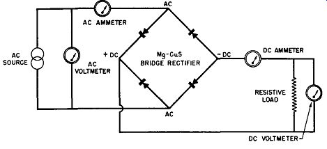
Fig. 6-13. Experimental Setup for Single-Phase, Full-Wave, Magnesium-Copper
Sulfide Bridge Rectifier.
The last experimental set-up to be described in connection with the temperature effects of the magnesium-copper sulfide rectifier cell gives the over-all effect of temperature upon the cell's rectified output. The circuit employed is given in Fig. 6-13 and snows a single-phase, full-wave bridge rectifier using magnesium-copper sulfide cells; this bridge is excited by a constant AC voltage of 12.8 volts rms. The output of the magnesium-copper sulfide bridge rectifier feeds a constant resistance load of 0.75 ohm. The resistive load is shunted by a DC voltmeter to indicate the DC output voltage while a DC ammeter in series with the output indicates the DC output current. In a like manner, an AC voltmeter across the AC source measures the applied input voltage and an AC ammeter in series with the rectifier input measures the AC current drawn by the rectifier.
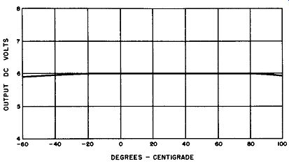
Fig. 6-14. DC Output Voltage of Single-Phase, Full-Wave, Magnesium-Copper
Sulfide Bridge Rectifier Versus Temperature.
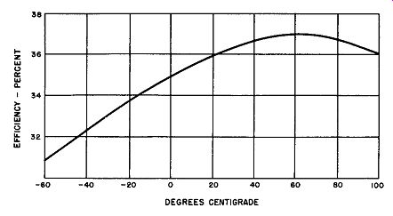
Fig. 6-15. Efficiency Versus Temperature for a Single-Phase, Full-Wave,
Magnesium-Copper Sulfide Bridge Rectifier Feeding A Resistive Load.
Again the rectifier is placed within a temperature chamber and exposed to a wide range of temperatures. Fig. 6-14 presents graphically the DC output voltage as a function of temperature. As one would expect from a study of previous experiments in Figs. 6-11 and 6-12 which indicated negligible resistance change in the cell, the output voltage of the magnesium-copper sulfide bridge rectifier is remarkably constant over the wide temperature range of -60 to +100 degrees Celsius; there is but a slight dip at the temperature extremes.
The experimental set-up of Fig. 6-13 also permits one to determine how the efficiency of the magnesium-copper sulfide rectifier varies with temperature. Efficiency of the rectifier is defined by the following formula:
This information is obtained experimentally by the set-up of Fig. 6-13 and the result is plotted graphically. Fig. 6-15 displays the curve. Here one will note that the efficiency is a minimum of 31 % at-60 degrees Celsius; the efficiency is a maximum of 37% at +60 degrees Celsius; and it is about 36% at +100 degrees Celsius. Using the efficiency figure of 36%, which it is at 20 degrees Celsius, as a reference (this temperature is that considered as normal) the tempera- ture extremes then cause a 5% decrease at-60 degrees Celsius and a 0% increase at +100 degrees Celsius.
Voltage-Resistance Characteristics
In the forward direction the magnesium-copper sulfide rectifier cell exhibits a very large resistance to forward current flow until the applied voltage (copper sulfide polarized positive and the magnesium base polarized negative) exceeds the critical initiating voltage of about 0.8 volt DC or AC peak value. When the initiating voltage is applied to the cell the forward resistance drops abruptly to a low value and de creases as the forward current increases. As the applied voltage is lowered from the initiating value for the magnesium-copper sulfide cell the forward resistance of the cell is maintained at a constant value.
In the reverse direction the resistance is not infinite as substantial leakage current flows during this part of the cycle.
It can be seen from the voltage-amperage curves of Fig. 6-9 that the resistance change with the applied reverse voltage is not linear and it is more nearly coincident than in the forward direction.
Because of the heavy leakage current and the hysteresis effects exhibited by the magnesium-copper sulfide cell in its voltage-resistance properties, it is not suitable for instrument or control applications. Its adverse voltage-resistance characteristics are not objectionable for the application for which the magnesium-copper sulfide rectifier is most suited--heavy current, low-voltage rectification.
Voltage Rating of the Cell
The voltage rating of the magnesium-copper sulfide rectifier cell is 3.5 volts rms. This low voltage rating for this cell makes it necessary to place too many cells in series in order to achieve high voltage ratings for rectifier stacks. For this reason magnesium-copper sulfide rectifier stacks having voltage ratings greater than 50 to 60 volts rms are not economical unless high temperatures or other unusual requirements justify the higher cost.
Current Rating of the Cell
The magnesium-copper sulfide rectifier cell has a higher current rating than the two types of metallic rectifiers previously described. It will be recalled that current rating is a function of heat dissipation, thus, such ratings as are given must be qualified as to the cooling methods used. When forced draft cooled, the magnesium-copper sulfide rectifier cell has a current rating as high as 50 amperes per square inch. When the same cell is convection cooled the current rating drops to about 15 to 16 amperes per square inch. For design purposes a conservative figure of current rating to remember is about 35 amperes per square inch under forced draft cooling. All these current ratings are for an ambient of 40 degrees Celsius.
Voltage Regulation
In the conducting direction the magnesium-copper sulfide rectifier stacks have an extremely low internal resistance which decreases as the current increases. This property of the rectifier promotes good DC output voltage regulation over a wide range of heavy load conditions. The regulation of a single-phase, full-wave magnesium-copper sulfide bridge rectifier depends upon the type of load it is feeding. A resistive load provides the best regulation, the full-load voltage being 75 to 80 percent of the no-load voltage. The inductive load provides the next best regulation and the capacitive load the poorest regulation.
The voltage regulation of the magnesium-copper sulfide rectifier stack is not favorable when compared with the previous types of metallic rectifiers described, but the reader must remember the much heavier load currents involved. If closer voltage regulation is desired, it is possible to use simple compounding schemes to provide more nearly constant output voltage over the load range.
Efficiency
The efficiency of the magnesium-copper sulfide rectifier is practically constant with respect to hours of use, wide range of load, and ambient and operating temperatures. As a single-phase, full-wave rectifier, its efficiency is in the neighborhood of 35 to 40 percent when it is feeding a resistive load or an inductive load, and 40 to 45 percent when feeding a capacitive or storage battery load. As a three-phase full-wave rectifier the magnesium-copper sulfide rectifier's efficiency is independent of the type of load and is between 50 to 60 percent.
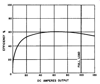
Fig. 6-16. Efficiency Characteristics of a Magnesium-Copper Sulfide Rectifier
Employed In a Three Phase, Full-Wave Bridge Circuit.
It will be recalled that the forward voltage drop across the magnesium-copper sulfide rectifier cell is practically constant regardless of current density. It is this property along with the excessive leakage current which limits the wattmeter efficiency of this rectifier to about 60 percent. Fig. 6-16 shows in graphical form the DC efficiency curve with respect to load.
It will be observed that after the 20 percent loading of the three-phase, full-wave bridge rectifier, the efficiency remains practically constant up to 120 amperes output, this output representing 20 percent overload.
To study the change of efficiency with respect to temperature refer to Fig. 6-15.
Power Factor
In common with the other two types of metallic rectifiers described previously, the magnesium-copper sulfide rectifier is essentially a resistive device at power frequencies.
Because of the other properties already described, this rectifier can not be used for signal detection or control valve purposes, hence, it is limited to power frequencies where full advantage may be taken of its heavy current rating. At power frequencies its power factor is unity. In practical circuit application the power factor will be determined by its associated circuit components.
Frequency Characteristics
The heavy current rating and the peculiar threshold properties limit the use of the magnesium-copper sulfide rectifier to power frequencies.
At 60 cycles per second this rectifier's full current rating may be utilized. At 25 cycles per second, it is necessary to reduce the current rating by 25 percent, while at 400 cycles per second the maximum current rating may be increased by 50 percent.
Effect of Idleness and Speed of Operation
Over the temperature range of -70 to + 130 degrees Celsius (-94 to +265 degrees Fahrenheit) the speed of operation of the magnesium-copper sulfide rectifier is practically instantaneous. When the rectifier has been stored or has been idle for an appreciable period of time some deformation of the rectifying cells may occur. However, the cells will reform rapidly, when the rectifier is placed into service.
Ambient Temperature Effects
An outstanding feature of the magnesium-copper sulfide rectifier is that it will operate in high ambient temperatures which will destroy the copper oxide and selenium types of metallic rectifiers.
Magnesium-copper sulfide rectifiers may be operated continuously in ambient temperatures as low as -70 degrees Celsius (-94 degrees Fahrenheit) or as high as 120 degrees Celsius (248 degrees Fahrenheit) with slight change in efficiency or output voltage over operation secured at room temperature, 20 degrees Celsius (68 degrees Fahrenheit). The magnesium-copper sulfide rectifier stack ratings are based upon a 40 degree Celsius (104 degrees Fahrenheit) maximum ambient temperature.
Aging of Magnesium-Copper Sulfide Rectifiers
Aging, as interpreted by the definition as a change in the rectifier characteristics with time and usage is negligible in the magnesium-copper sulfide rectifiers. One advantage of this property of this rectifier is that designers of metallic rectifier power supplies using the magnesium-copper sulfide rectifier do not have to include transformer taps for adjustment of the input voltage to the rectifier to compensate for rectifier aging. This feature is especially convenient for manufacturers of electrical equipment who are reluctant to have non-technical people in the field make adjustments or changes on their equipment.
Life and Operating Temperature
Originally the magnesium-copper sulfide was considered to have a definite life span; however, improvements in the technique of manufacturing and a better understanding of its characteristics have now made it possible to state that if this rectifier's ratings are not exceeded, it, like the selenium and copper-oxide rectifiers, has unlimited life.
The temperature of the magnesium-copper sulfide rectifier stack for maximum life is about 85 degrees Celsius (185 degrees Fahrenheit). Magnesium-copper sulfide rectifiers operated in applications where the longest possible life is not a requisite, a stack operating temperature of 130 degrees Celsius (265 degrees Fahrenheit) is permissible. At this temperature many magnesium-copper sulfide rectifiers, on duty continuously, have been in operation in excess of 10,000 hours.
Operation at temperatures of 200 degrees Celsius or over, although successful and only achieved by the magnesium-copper sulfide rectifier, reduces its life to 500 to 1500 hours depending upon current and voltage factors.
Another factor besides the operating temperature of the magnesium-copper sulfide rectifier stack is the current density of the cells. Current density of the cell is defined as the DC amperes per square inch of the active rectifying area.
Where longest life of the rectifier is required, it is necessary to derate the current rating from its maximum value.
Threshold Characteristics
A study of the voltage-ampere characteristics (see Fig. 6-9) reveals that the magnesium-copper sulfide rectifier cell has a pronounced threshold voltage. This threshold voltage is in the conducting direction and has a value of 0.5 to 0.6 volt rms or about 0.8 volt DC or AC peak value.
That the magnesium-copper sulfide rectifier is not suit able for instrument rectifier applications and that its efficiency is limited to 60 percent maximum even for three-phase operation can be a credited to this threshold effect.
Future Outlook
It appears unlikely that there will be any revolutionary improvements in the properties of the magnesium-copper sulfide rectifier since it has seen many years of intensive development in the past. Although it is the only commercial rectifier which will operate successfully above 200 degrees Celsius, with reduced life, of course, its chief limitations are the low voltage per cell, about 3.5 volts rms, and the low conversion efficiency of 35 to 40 percent for single-phase, and from 50 to 60 percent for three-phase operation.
Because of its high temperature properties the magnesium-copper sulfide rectifier is under further development by the sponsorship of the Armed Forces for low-voltage, cathode heater supplies for electronic equipment.
The most recent improvement applied to the magnesium copper sulfide rectifier for high temperature application has been hermetic sealing. For, although this rectifier operates successfully at 200 degrees Celsius (with reduced life), full advantage of this property has not been exploited in the past because of the lack of protective coatings which would withstand the high temperature operation. The new solution to this problem is the hermetic sealing.
This technique involves electroformed magnesium-copper sulfide cells assembled upon a bolt and soldered into a bath-tub can such as used for hermetically sealed capacitors.
Terminal connections are secured through glass-to-metal or ceramic-to-metal seals. To facilitate cooling of the sealed rectifier stack, the bath-tub can is coated black. The outside dimensions of the hermetically sealed rectifiers developed thus far is 1 3/8 inches long, 1 1/4 inches high, and 1 13/16 inches wide. A rating for a typical hermetically sealed magnesium-copper sulfide rectifier for a resistive load are listed as follows: AC input voltage Normal output amperes DC Normal output volts DC Rated output amperes DC@ 200 C. Rated output volts DC @ 200 C. Maximum load amperes, any condition 16
0.7 8.4
0.9 6.7 1.5
The normal rating is at 35 to 40 degrees Celsius with a life rating of 10,000 to 20,000 hours to unlimited life, whereas the operation at 200 degrees Celsius results in a rectifier life of 1000 to 1500 hours.