AMAZON multi-meters discounts AMAZON oscilloscope discounts
Not all power supplies involve the conversion of a 120-volt a-c power source to various values of direct current. Sometimes it is necessary to change low-voltage direct current to a higher voltage, or an a-c output may be required from a d-c source. This chapter examines several rather new and novel power-supply circuits.
TRANSISTOR POWER CONVERTERS AND INVERTERS
Before the advent of the transistor, low-voltage d-c to high-voltage d-c power converters (such as those used to operate auto radios) employed an electromechanical switch called a vibrator. It provided the necessary rapid interruption of current so that a step-up transformer could be used to produce a higher voltage. A simplified example of this type of supply is shown in FIG. 1. The electromechanical vibrator operates much like a door buzzer-an electromagnet causes the movable armature to vibrate rapidly between the two current carrying contacts. This rapid switching action creates current pulses from the d-c power source in alternate halves of the primary winding.
Pulsating direct current in the primary of the transformer induces across the secondary of T1 a high-voltage alternating current which is rectified and filtered.
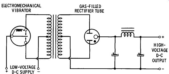
FIG. 1. Vibrator converter.
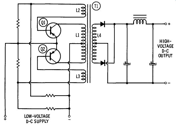
FIG. 2. Transistorized converter.
Although the electromechanical vibrator did its job fairly well, it had limitations. Because it employed moving parts, it was subject to mechanical failure within a relatively short time. Also, the electrical contacts would wear and impair circuit efficiency.
With the advent of the transistor, the mechanical vibrator has frequently been replaced by transistor switching. FIG. 2 shows a typical transistorized direct-current to direct-current converter. Transistors Q1 and Q2, the center-tapped primary winding (L1) , and the two feedback windings (L2 and L3) form an oscillator circuit. The pattern of oscillations is such that when Q1 is saturated (has a maximum collector current) and thus has a very low internal resistance, Q2 is cut off ( zero collector current). Likewise, Q1 is cut off while Q2 is saturated. This rapid switching from cutoff to saturation generates a square-wave current in center-tapped primary winding L1 of step-up transformer T1. Pulsating current through the primary induces a high voltage in secondary winding L4. The latter voltage is rectified and filtered to yield the desired d-c output voltage.
Mechanical-vibrator power supplies were generally designed with operating frequencies in the range of 60 to 300 Hz; transistor-converter operating frequencies range from 60 to 5000 Hz. Since transistor converters employ no moving parts, they can operate at much higher frequencies. This permits smaller values of filter elements to be used. Also, at higher operating frequencies, the power transformer need not have as much inductance, which means that less iron and copper are required in its construction. Consequently it is much lighter in weight than a transformer designed for 60-Hz operation.
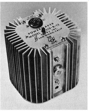
---------- An inverter that supplies up to 300 watts at 115 volts
a-c from a 12-volt battery. Courtesy Topaz Inc.
D-c to a-c power inverters operate basically in the same manner as the d-c to d-c converters just described. The major difference between the two is that the inverter is designed to provide an a-c output (most generally 60 Hz). That way the output may be used to operate equipment designed for regular house power.
RADIO-FREQUENCY POWER SUPPLIES
FIG. 3 is the schematic of a rather unusual type of power supply that is capable of efficiently providing very high voltages at low current. This circuit was widely used in the earlier tv receivers employing electrostatic-deflection picture tubes, and is still used in oscilloscopes and electrostatic dust precipitators.
As shown in FIG. 3, this supply consists of a radio-frequency oscillator, a high-voltage transformer, and a rectifier. The circuit values are selected to provide an oscillator frequency of approximately 80 kHz, with a power output of approximately 25 watts. The r-f energy developed in windings L1 and L2 is inductively coupled to the secondary, L3, which consists of many more turns than L1 and L2 so a high r-f voltage is induced in winding L3. This is applied to half-wave rectifier V2. The rectified voltage is filtered by R1 and C3. Because of the very high ripple frequency, the value of the filter capacitor is quite small, normally 500 pf.
The r-f power-supply output can be voltage-regulated by the closed loop method shown in FIG. 4. A portion of the output voltage is sampled and compared with a fixed reference voltage. The resulting error signal is amplified and used to vary the screen-grid voltage of oscillator tube V1.
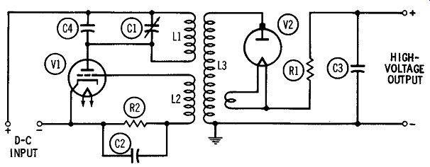
FIG. 3. Radio-frequency high-voltage power supply.
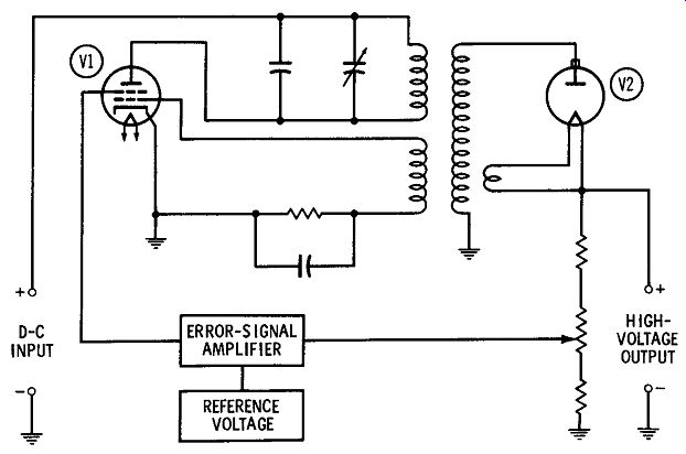
FIG. 4. Voltage-regulated r-f power supply.
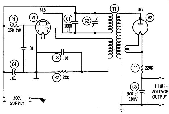
FIG. 5. Practical high-voltage power supply.
------------------
Parts List for FIG. 5
Item No. Description
C1 Capacitor, 1000 pf, mica
C2 Capacitor, trimmer, 500-1000 pf, mica
C3 Capacitor, .01 mfd, mylar
C4 Capacitor, .01 mfd, mylar
C5 Capacitor, 500 pf, 1 0KV
R1 Resistor, 15K ohms, 2 watts
R2 Resistor, 22K ohms, ½ watt
R3 Resistor, 220K ohms, ½ watt
T1 Transformer, high-voltage (Spellman 10-15KV-1, or equivalent)
V1 Tube, 6L6
V2 Tube, 1
B3
----------------
To see how this works, assume that the load current increases. This will increase the error signal in the positive direction, causing the voltage applied to the screen grid of V1 to increase. The amplitude of oscillation developed by V1 will likewise increase. In turn, this will increase the voltage developed across the secondary of T 1 and the rectified output voltage. If the output voltage should increase, the reverse action will occur-the screen voltage of V1 will decrease and the rectified output voltage will drop accordingly.
The 5KV d-c power supply shown in FIG. 5 is ideal for the high voltage crt requirements of an oscilloscope, insulation tester, electronic dust precipitator, etc. The supply is constructed around an inexpensive r-f high-voltage transformer that is commercially available. The operation of this supply is identical with the one shown in FIG. 4.
The construction is not particularly critical, although care must be taken that adequate insulation is used around high-voltage rectifier V2, its associated wiring, and filter capacitor C5. Adjustment of the supply consists of setting C2 for maximum high voltage output. Although, because of its low current output, this supply is not considered dangerous, care should be taken not to get directly across the output terminals when it is operating.