AMAZON multi-meters discounts AMAZON oscilloscope discounts
Semiconductor rectifiers offer a number of advantages over vacuum-tube and gas-filled rectifiers. Chief among these are smaller size, greater reliability, absence of a heated cathode, lower forward-voltage drop, and greater mechanical ruggedness.
FIG. 1 illustrates how the semiconductor rectifier may be used in the four basic rectifier circuits: half-wave, full-wave, bridge, and voltage-multiplier. Although there are various types of rectifiers which are broadly classified as "semiconductor rectifiers," in this chapter we will deal primarily with silicon rectifiers, as they are the type most commonly used in power supplies.
SEMICONDUCTOR-RECTIFIER RATINGS
As in the case of high-vacuum and gaseous rectifiers, semiconductor rectifiers have specific operating limitations. In circuits where they are employed it is very important that these ratings not be exceeded.
Peak Inverse Voltage (piv)
The peak inverse voltage, sometimes referred to as the peak reverse voltage ( prv), is a rating of a semiconductor diode that denotes the maximum reverse voltage which may be applied to the diode. It is dependent in part upon the temperature of the diode, decreasing as the diode temperature increases.
(A) Half-wave.
(B) Full-wave.
(C) Bridge.
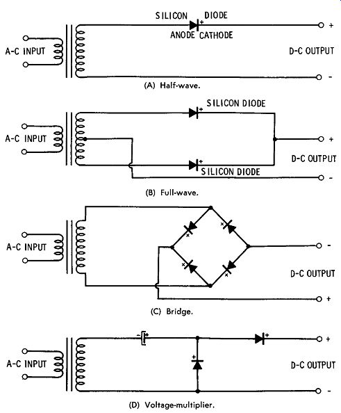
FIG. 1. Semiconductor-rectifier circuits.
Peak Surge Current
This rating refers to the peak instantaneous value of forward current which a semiconductor diode can safely conduct for a limited time ( usually one cycle of the applied alternating current). It is especially significant in circuits where the output of the semiconductor diode is applied to a capacitor-input filter. Under this condition, care must be taken to assure that the initial current charging the input filter capacitor does not exceed the peak surge-current rating. When a large value of input filter capacitor is required, a current-limiting resistor should be placed in series with the input capacitor.
Average Forward Current
The average forward-current rating of a semiconductor diode refers to the maximum value of forward current which the diode can safely handle on a continuous basis. Average forward-current ratings of silicon diodes range from a fraction of an ampere to many hundred amperes.
SERIES CONNECTION OF SEMICONDUCTOR DIODES
Often it may be necessary to connect several semiconductor diodes in series in order to obtain a higher piv ( peak inverse voltage) than is obtainable from a single unit. In order to do this safely, several pre cautions must be observed.
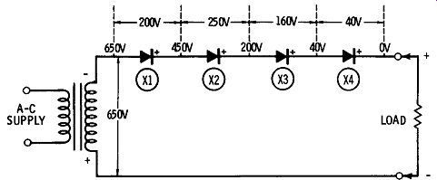
FIG. 2. Voltage distribution across series-connected diodes.
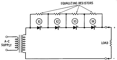
FIG. 3. Use of equalizing resistors.
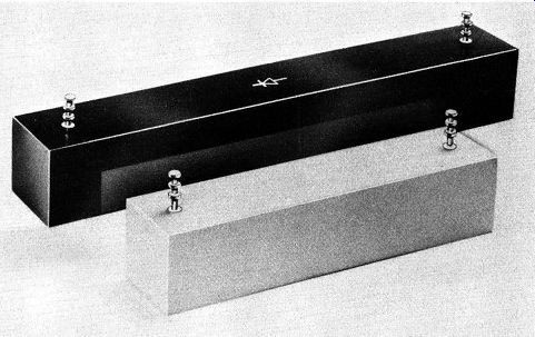
----------- Courtesy Electronic Devices, Inc. A commercial silicon-rectifier
unit to be used in high-voltage (3000 to 50,000 volts) applications.
FIG. 2 shows four typical series-connected silicon diodes in a simple half-wave power-supply configuration. Notice that the reverse voltage distribution across the diodes is unequal, the voltage across X 1 and X2 being higher than that across X3 and X4. The cause of this voltage variation is the difference in reverse leakage currents of the individual diodes. In this situation, the voltage across one or more of the series-connected diodes may exceed their PIV rating, causing their failure.
FIG. 3 illustrates a method for equalizing this variation in voltage division across the diodes. A resistor is connected across each diode, the value of each resistor being low in comparison to the normal re-verse resistance of the diodes. The effect of these resistors is to provide a constant voltage division across the diode string. Typical values of these resistors are 250,000 to 500,000 ohms. Their value is not critical.
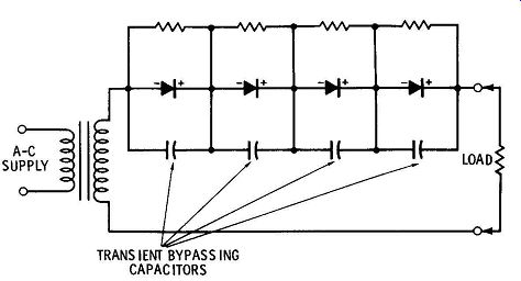
Fig. 4. Use of bypass capacitors.
In addition to equalizing resistors, it is wise to place bypassing capacitors across each series-connected diode, as shown in FIG. 4.
These capacitors bypass any transient-voltage pulses in the power line feeding the diodes. Transients occasionally reach a high enough amplitude to exceed the piv of the diodes. The value of these bypass capacitors should be between .01 and 0.1 mfd, and their voltage rating should be equal to or greater than the piv rating of the diode across which they are connected.
Another method of reducing the chance of diode damage by line voltage transients is shown in FIG. 5. A thyrector diode is connected directly across the primary of the transformer feeding the diodes. The thyrector is a special type of semiconductor which will abruptly con duct in either direction when the voltage across it exceeds a certain predetermined value, thereby absorbing any voltage transients above its design value. Below this value, the thyrector appears as an open circuit. In effect, the thyrector is like two back-to-back zener diodes.
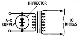
FIG. 5. Use of thyrector diode.
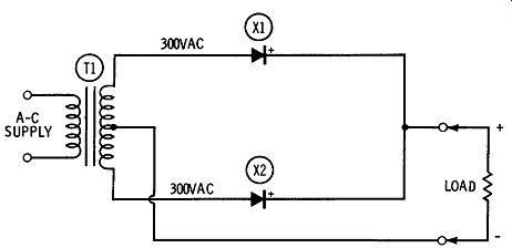
FIG. 6. Full-wave semiconductor-rectifier circuit.
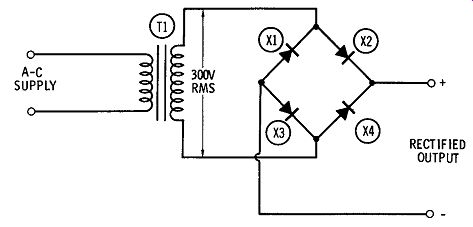
FIG. 7. Bridge rectifier.
SUBSTITUTING FOR TUBE RECTIFIERS
Because of the much smaller physical size and lower voltage drop of silicon rectifiers, it is often advantageous to use them as replacements for their vacuum-tube or gas-filled rectifier counterparts in existing power supplies. When this is done, certain precautions must be observed if satisfactory performance is to be achieved. To see what these are, examine the following circuits.
FIG. 6 shows a typical full-wave rectifier circuit using silicon diodes. The piv rating of X1 and X2 should be equal to at least the peak value of the voltage appearing across the entire secondary of T 1-not just one-half of the winding as you might expect. The reason for this becomes clear when you examine the circuit of X1 and X2 during a half-cycle of operation. Notice that while X2 is conducting, the full secondary voltage appears across the reverse-biased X1. In effect, X2 is a short circuit. On the following half-cycle of operation X1 is conducting, thereby placing the full secondary voltage of T1 across X2. From this, it is apparent that the piv rating of X1 and X2 should equal at least the peak voltage across the secondary of T1 1.4 x 600 volts, or 840 volts. Actually, an additional 20 percent should be added to this value to allow for power-line voltage variations. X1 and X2 should therefore have a piv rating of 1080 volts.
Either 1000-volt diodes may be used, or X1 and X2 may be made up of strings of series-connected diodes of lower piv ratings. If the latter is done, the precautions outlined earlier in this chapter should be observed.
FIG. 7 shows a bridge-rectifier configuration using silicon diodes.
The bridge arrangement is an advantage under some circumstances since a center-tapped transformer winding is not required.
The piv ratings of X1, X2, and X3, and X4 should be at least equal to the peak value of the voltage developed across the secondary of T1. In the case of FIG. 7, this would be 300 x 1.4, or 420 volts.
Add to this a 20-percent safety factor, and we get a piv rating per diode of 504 volts. This can be rounded off to 500 volts. If desired, series-connected diodes may be used for any or all of the four rectifiers.
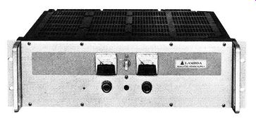
------ Courtesy Lambda Electronics Corp. An all-silicon regulated power
supply with continuously variable voltage output.
When silicon diodes are substituted for vacuum tubes, the rectified d-c voltage from the diodes will increase. The reason is that the diodes have a lower forward-voltage drop than tubes. For example, the for ward-voltage drop across a typical silicon diode will be approximately one volt, while the voltage drop across a typical vacuum-tube rectifier may be as high as 30 volts. This higher output voltage can, under some circumstances, cause difficulties in the circuit being supplied with power by the diodes.
FIG. 8 shows how the voltage output of a full-wave rectifier circuit can be decreased. Resistor R 1 has been placed in series between the output of the diodes and the input of the filter. The correct value of this series resistor can be obtained by the use of Ohm's law: where, R=E I R is the value of the resistor, in ohms, E is the desired drop in voltage, in volts, I is the d-c output current, in amperes.
The required wattage rating of the resistor can be calculated from
W= E^2 / R
where, E is the voltage drop across the resistor, in volts, R is the value of the resistor, in ohms.
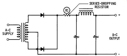
FIG. 8. Use of series-dropping resistor.
Another method of voltage dropping is considerably more efficient than the resistor method just described. A choke can replace the series-dropping resistor ( FIG. 8) since it reduces the output of the filter to nearly the rms value of the input to the rectifier. Without choke or resistor the output would be nearly equal to the peak value.
This choke also makes life easier for the rectifier diodes by greatly reducing the high initial charging current of the input-filter capacitor.
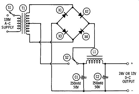
FIG. 9. Dual-voltage power supply.
---------------
Parts List for FIG. 9
Item No.
C1 C2 L1 S1 S2 T1 X1 X2 X3 X4
Description
Capacitor, 250 mfd, 50 volts, electrolytic
Capacitor, 250 mfd, 50 volts, electrolytic
Choke, .035 hy, 2 amps (Knight 54D2343, or equivalent)
Switch, spst
Switch, spst
Transformer, power, 25 volts center-tapped, 1 amp (Knight 54D1421, or equivalent)
Rectifier, silicon, 1 N2482
Rectifier, silicon, 1 N2482
Rectifier, silicon, 1N2482
Rectifier, silicon, 1N2482
---------------------
A DUAL LOW-VOLTAGE POWER SUPPLY
The low-voltage power supply shown in FIG. 9 can furnish two switch-selected d-c output voltages at a current rating of up to 1 amp.
The supply uses step-down transformer T1 in conjunction with a bridge rectifier composed of X1, X2, X3, and X4. The output from the rectifier is filtered by C1, C2, and LL The dual voltage is obtained by making use of either the entire bridge rectifier ( full output voltage) or half of the bridge and the secondary center tap (half voltage). The full-voltage output of the supply is 24 volts at the rated load of 1 amp, and the half-voltage output is 12 volts, also at 1 amp. Since a capacitor-input filter is used, the output voltages from the supply are higher under light loads.
A 600-VOLT "HAM-TRANSMITTER" POWER SUPPLY
This high-voltage power supply is ideal for a medium-power transmitter. The supply provides 600 volts at 200 ma, with more than adequate filtering. The unit is physically small because no bulky mercury vapor rectifier tubes are required. As an added bonus, the supply provides "instant-on" operation. There are no tubes that need to warm up before they can function, so the voltage is available at the output the instant the switch is closed.
As shown in FIG. 10, the voltage across the secondary of power transformer T1 is rectified by a full-wave circuit consisting of X1, X2, X3, and X4. Each half of the full-wave rectifier consists of two series connected 800-piv silicon diodes. Equalizing resistors and transient bypassing capacitors are connected across the diodes. As mentioned earlier in this chapter, the high piv rating of the diodes in a full-wave rectifier is necessary because the full peak voltage of the transformer secondary appears across the nonconducting diodes.
The output from the rectifier is applied to the filter consisting of L1, L2, CS, C6, C7, C8, R1, R2, R3, and R4. A choke-input filter is used both to limit the initial charging current drawn from the rectifier and to improve voltage regulation. Because of the choke-input filter, the output voltage of this supply will vary only slightly from no load to full-load operation.
In order to obtain the required voltage rating, the filter capacitors are stacked-CS with C6, and C7 with C8. The actual capacitance is half the value of each of the stacked capacitors-20 mfd. Equalizing resistors are placed across the capacitors to assure equal voltage distribution across them.
VOLTAGE-MULTIPLIER CIRCUITS
Because of their small physical size and their freedom from filament power requirements, silicon diodes are ideally suited to voltage-multi plier circuits. The following are a few practical examples of such circuits.
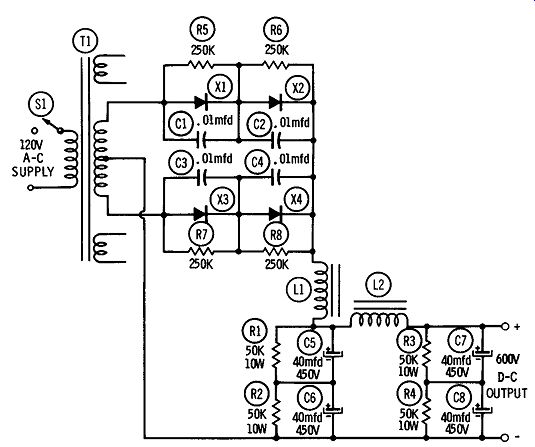
FIG. 10. Transmitter power supply.
--------------------
Parts List for FIG. 10
Item No.
C1 C2 C3 C4 C5 C6 C7 C8
L1 L2
S1
T1
X1 X2 X3 X4
Description Capacitor, .01 mfd, 1000 volts, mylar Capacitor, .01 mfd, 1000 volts, mylar Capacitor, .01 mfd, 1000 volts, mylar
Capacitor, .01 mfd, 1000 volts, mylar
Capacitor, 40 mfd, 450 volts, electrolytic Capacitor, 40 mfd, 450 volts, electrolytic
Capacitor, 40 mfd, 450 volts, electrolytic Capacitor, 40 mfd, 450 volts, electrolytic
Choke, 6 hy, 200 ma (Knight 54D4704, or. equivalent)
Choke, 6 hy, 200 ma (Knight 54D4704, or equivalent)
Switch, spst Transformer, power, 600 volts, 200 ma (Knight 54D2549, or equivalent)
Rectifier, silicon (Sarkes Tarzian FS, or equivalent)
Rectifier, silicon (Sarkes Tarzian FS, or equivalent)
Rectifier, silicon (Sarkes Tarzian FS, or equivalent)
Rectifier, silicon (Sarkes Tarzian FS, or equivalent)
--------------------------------
Voltage-Doubler Power Supply
The power supply in FIG. 11 is ideal for the experimenter who needs a well-filtered voltage source for experimental vacuum-tube circuits. It may also be integrated into a new design such as a ham transmitter or exciter.
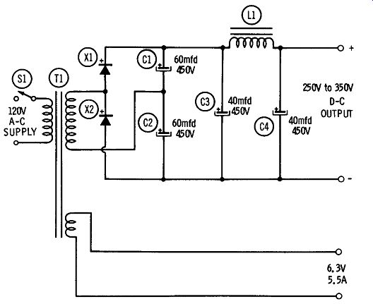
FIG. 11. Dual low-voltage power supply.
------------------
Parts List for FIG. 11
Item No.
C1 C2 C3 C4
L1 S1 T1 X1 X2
Description
Capacitor, 60 mfd, 450 volts, electrolytic Capacitor, 60 mfd, 450 volts, electrolytic Capacitor, 40 mfd, 450 volts, electrolytic Capacitor, 40 mfd, 450 volts, electrolytic Choke, 5 hy, 100 ma (Knight 5402348, or equivalent)
Switch, spst
Transformer, power. Secondaries: 135 volts, 200 ma; 6.3 volts, 5.5 amps (Knight 5403708, or equivalent)
Rectifier, silicon, 1N2483
Rectifier, silicon, 1 N2483
------------
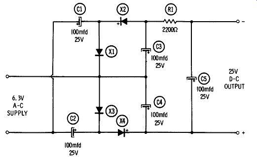
Fig. 12. Voltage-quadrupler bias supply.
---------------
Parts List for FIG. 12
Item No. Description
C1 Capacitor, 100 mfd, 25 volts, electrolytic C2 Capacitor, 100 mfd, 25 volts, electrolytic C3 Capacitor, 100 mfd, 25 volts, electrolytic C4 Capacitor, 100 mfd, 25 volts, electrolytic C5 Capacitor, 100 mfd, 25 volts, electrolytic R1 Resistor, 2200 ohms, ½ watt X1 Rectifier, silicon, 1 N2482 X2 Rectifier, silicon, 1N2482 X3 Rectifier, silicon, 1N2482 X4 Rectifier, silicon, 1 N2482
-------------------
As shown in FIG. 11, the power supply consists of power transformer T1 ; diodes X1 and X2; capacitors C1, C2, C3, and C4; and choke L1. In operation, the voltage across the secondary of T1 is fed to a full-wave voltage doubler. The voltage at the output of the rectifier is filtered by L1, C3, and C4.
The output voltage from the power supply will be approximately 250 volts at a load current of 100 ma. It will rise to a maximum of about 350 volts at no-load.
Voltage-Quadrupler Bias Supply
This is a relatively simple way of obtaining a bias supply up to 25 volts without the use of an extra transformer or special tapped secondary winding. As shown in FIG. 12, a voltage quadrupler consisting of X1, X2, X3, X4, C1, C2, C3, C4, C5, and R1 is connected across a 6.3-volt filament winding of the equipment in which the bias supply is to be incorporated. The output of the quadrupler is applied to a simple filter consisting of R1 and C5. A resistor is used in place of the more conventional filter choke since the current drawn from the bias supply is almost negligible.