AMAZON multi-meters discounts AMAZON oscilloscope discounts
Just as there are many electronic devices which must be operated from a source of constant voltage, so are there many types of circuitry and equipment which require a source of constant current for their operation. In this chapter the various methods of obtaining a constant current source are examined. Both vacuum-tube and semiconductor current regulators are described.
One application of a constant-current source is the testing of certain types of semiconductor devices. For example, in the evaluation of zener diodes, it is important to use a constant-current source. Also, most tunnel-diode circuits perform at their best when operated from a source possessing constant-current characteristics.
REGULATING WITH A SERIES RESISTOR
The process of voltage regulation consists of maintaining a constant voltage across a load in spite of variations in the load and the current through it. By contrast, current regulation is achieved when the current through a load remains the same although the resistance of the load and/ or the voltage across it may change.
Perhaps the simplest method of obtaining a relatively constant current source is to place a resistance in series between the source of operating voltage and the load, as shown in FIG. 1. The value of series resistor R1 should be about ten times that of the load. Under these conditions resistor R1 is the factor that limits the current in the circuit. Variation in the resistance of the load has an almost negligible effect. This can be seen more easily by studying an example. If the operating voltage is 100 volts, R1 is 1000 ohms, and the load is 10 ohms, current in the circuit will be
E 100 I = R = 1000
+ 10
= .099 amp
If the load changes to zero ohms, the current will be 100 I= 1000
+
0
= 0.1 amp If the load doubles, to 20 ohms, the current will be 100 I = 1000
+ 20
= .098 amp
Thus a change of ± 100% in the load resulted in a current change of
± 1%.
The disadvantage of this method is that it is very wasteful. All the power dissipated by R1, which is nearly all the power in the circuit, serves no useful purpose. However, there are circumstances under which this method is useful.
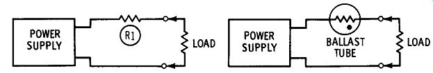
Fig. 1. Simple method of obtaining a constant-current source.
FIG. 2. Use of ballast tube to obtain constant current.
Another simple type of current regulator is shown in FIG. 2.
Known as a "ballast tube," this current regulator was widely used at one time to maintain a constant current to a load connected to the 120-volt power line.
The ballast tube consists of an iron-alloy wire element enclosed in a special gas atmosphere. In operation, current variations through the ballast-tube element cause it to change temperature. This heating and cooling varies the resistance of the element proportionally-as the temperature increases, so does the resistance, and vice versa. When the ballast tube is connected in series with the load, an increase in current will cause an increase in temperature and, hence, resistance of the ballast-tube element. This greater resistance reduces the current in the load, keeping it close to its original value. Conversely, a decrease in current lowers the temperature of the ballast-tube element, and more current will be delivered to the load.
A modified version of the ballast tube, called a surgistor, is found in many television receivers. The surgistor is connected in series with the tube-heater string of the tv receiver. When the receiver is first turned on, the tube heaters have a cold resistance that is much less than their operating-temperature resistance. The surgistor limits the initial inrush of current by having a high resistance when it is cold.
This high resistance limits the initial current through the tube heaters to safe values. As the tube heaters warm up, so does the surgistor because of the passage of current through it. The resistance of the surgistor drops, and there is normal operating current in the tube heaters.
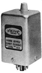
-------- A constant-current power supply that provides exactly 25 milliamperes in spite of wide variations in load and input voltage. Courtesy Viking Industries, Inc.
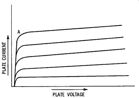
Fig 3. Pentode characteristic curves for various control-grid voltages.
ELECTRONIC METHODS
Although the ballast tube is capable of providing some current regulation, its reaction time is relatively slow. The reason for this is the thermal lag of the element-it takes a second or so for the ballast-tube element to change temperature after the current through it has changed. As a result, the ballast tube cannot correct for rapid changes in current through it.
This problem can be solved by using an electronic current-regulator system. Let us examine a vacuum-tube regulator first, to get the feel of electronic current regulation. FIG. 3 is the family of plate curves for a typical pentode. Notice that above the knee, point A, the plate current remains essentially constant for large changes in plate voltage.
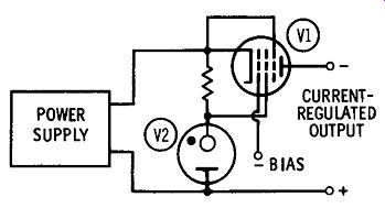
FIG. 4. Pentode current regulator.
FIG. 4 shows how these pentode characteristics can be put to use in a practical current regulator. Pentode V1 is connected so that the external load is in its plate circuit. Proper values of control-grid bias and screen voltages are used to operate the pentode in the region where the plate-current characteristic is constant. Since the plate current of a pentode is highly dependent on the value of screen voltage, the latter is held at a constant potential by gas-filled voltage regulator V2.
FIG. 5 is the transistorized version of the above circuit. Transistor
Q1 is biased for constant collector current, and the external load is connected in series with the collector. Zener diode X1 holds the base of Q1 at a fixed potential. If the collector current begins to change, the resulting change in base-emitter voltage returns the load current to its original value.
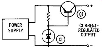
FIG. 5. Transistor current regulator.
Another current regulator is shown in FIG. 6. Notice that this circuit is similar to the voltage regulator shown in FIG. 13. Referring to FIG. 6, assume that the current drawn by the external load increases. This causes a greater current through R1, resulting in a greater voltage drop across it. The base of Q2 will now become more negative with respect to its emitter, which is held at a constant voltage by zener diode X1. The collector current of Q2 will increase, thereby causing the collector to become less negative. In turn, the base of Q1 will become less negative with respect to its emitter, and as a result, Q1 will pass less current to the external load-bringing the load current back down to its original value.
A decreasing load current will have the reverse action. The reduced voltage drop across R1 will cause the base of Q2 to become less negative with respect to its emitter, thus increasing the negative collector voltage of Q2. Since the collector of Q2 is direct-coupled to the base of Q1, base current in the latter will increase, increasing the current passed on to the load.
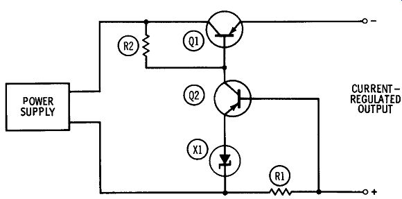
FIG. 6. Current regulator with error-amplifying stage.
Notice that although current regulation was obtained with this circuit, it is actually the voltage drop across series resistor R1 that sup plied the error signal. This, of course, is satisfactory because the voltage drop across a resistor is directly proportional to the current through it.