AMAZON multi-meters discounts AMAZON oscilloscope discounts
Gaseous components have a long history in electronics technology. If you are a grandfather, you may recall the "soft" detector tubes used during World War 1. These tubes were triodes with a certain trace of gas and provided unusually sensitive detection when the tube was critically biased. And if you happen to be a great-grandfather, you may remember singing arcs and Poulsen arcs. These were the first gaseous components used to transmit voice by radio.
Today gaseous components have evolved into more sophisticated types, as exemplified by familiar neon bulbs, voltage regulator tubes, and thyratrons. The advantages of gaseous components are realized in applications which require switching action or current control with low internal resistance.
Since ionized gas glows, gaseous components are also used as indicators. Low internal resistance is desirable in high-current applications because efficiency is improved--the J2R loss through a thyratron is very small, compared to the loss in a comparable high-vacuum tube.
When a gas tube is designed so that more of the cathode and anode area is covered by the glow discharge as the current is increased, the voltage drop remains quite constant between anode and cathode over a wide current range. This type of gas tube is used as a voltage regulator. Gas tubes can be connected in series to increase the available voltage drop.
Tests of gaseous components differ somewhat from tests of high-vacuum tubes, for example, because a basic switching action is involved, instead of a valving action. Many tests can be made satisfactorily with meters, although a scope provides more complete data. Beginners are sometimes surprised to find that most gaseous components have negative-resistance intervals. This fact becomes apparent in scope tests.
BASIC PRINCIPLES OF GASEOUS COMPONENTS
A wide range of gaseous components is encountered in electronics technology. Air, of course, is a gas and probably the simplest gaseous component is the air spark-gap. Occasionally a color-TV receiver utilizes a spark gap in the high-voltage section to protect the picture tube against excessively high voltage surges. The spark gap acts as a switch. Spark gaps have been used to measure voltages, and in the absence of a high-voltage probe, a needle gap can be used for approximate measurements of potentials less than 30,000 volts. Fig. 1 shows the maximum gaps for various voltages for No. 1 sharp needles, as well as for 1-inch brass spheres. Note that gap spacing versus voltage is linear for needle points and is nonlinear for spheres.
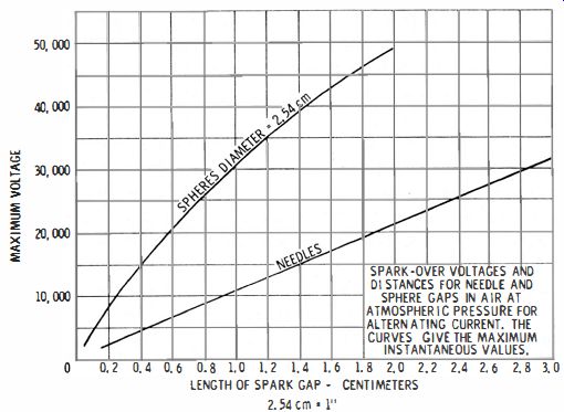
Fig. 1. Voltage to space relationship for spark gaps.
Most gaseous components operate at pressures that are less than that of the atmosphere. Some familiar examples are neon bulbs, thyratrons, and voltage-regulator tubes. A neon bulb is similar to a spark gap in that it does not conduct until the applied voltage passes a certain critical value. Then the gas ionizes and glows. The resistance of the neon bulb suddenly drops from infinity to a finite value. For example, at 54 volts a neon bulb typically draws 1 ma ; therefore its DC resistance is 54K. However, within its conduction region, its DC resistance is much lower, for example, say 2,500 ohms.
Conductance Resistance
As shown in Fig. 2, the characteristic of a neon bulb is a special type of nonlinear resistance. It has a point of discontinuity called the firing point, and past the firing point, the bulb is a conductor instead of an insulator. The slope of the conduction interval gives the conduction resistance of the bulb. This is a parameter of central concern in voltage regulator applications. Note that the power dissipated by the bulb is simply the product of the voltage across the bulb and the current flow. Thus, referring to Fig. 2, the power dissipation at 40 volts is zero, and the power dissipation at 55 volts is 1.21 watts. This power is dissipated as heat.
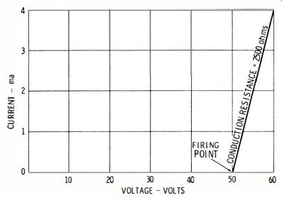
Fig. 2. Neon-bulb characteristic.
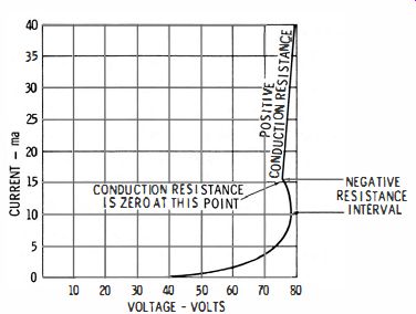
Fig. 3. VR tube often has a negative-resistance interval.
The conduction resistance of a thyratron is much lower than that of a neon bulb, and is regarded as practically zero in a good tube. As a thyratron ages to the extent that it is considered defective, its conduction resistance becomes appreciable and can be measured with a simple oscilloscope test, as will be explained subsequently. Also, the conduction resistance of a voltage-regulator tube is very low and is also commonly regarded as practically zero. However, the conduction resistance does slightly vary in a perhaps unexpected manner.
As shown in Fig. 3, a typical voltage-regulator tube has a very low conduction resistance over a current range of 10 to 40 ma. However, between 10 and 15 ma, the current increases as the voltage decreases-this is the negative-resistance interval. If appreciable circuit reactance is connected across the tube during this interval of current demand, spurious oscillation will occur. During the higher current interval, the tube has a low, positive conduction resistance. The voltage drop across a typical VR tube varies only 3 or 4 volts over its rated current range.
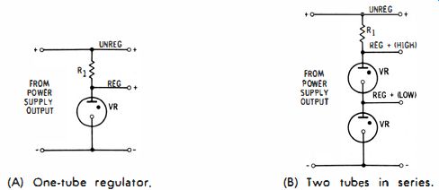
Fig. 4. Basic configuration for VR tubes. (A) One tube regulator. (B) Two
tubes in series.
Zero-Resistance Point
Any component that has adjacent positive and negative resistance intervals also has a zero-resistance point on its characteristic. This point occurs where the slope of the tangent is infinite-The zero-resistance point is indicated on the VR characteristic indicated in Fig. 3.
Since gas tubes have a conduction resistance that is a low positive, negative, or zero value, external circuit resistance must always be provided (Fig. 4A) to limit the current flow and not exceed the rating of the tube; otherwise, the tube will overheat and explode. Beginners often explode neon bulbs by connecting them across a 117-volt line without a series resistor.
Typical, small neon bulbs are rated for a maximum current of 2 ma. Therefore, a 56-K resistance, or greater must be connected in series with the bulb for 117 -volt operation. "High brightness" neon bulbs are commonly rated for a maximum current flow of 6 ma.
Series Connection of Gas Tubes
Note that voltage-regulator tubes can be connected in series (Fig. 4B) to double the output voltage. VR tubes are rated for conduction drops of approximately 75, 90, 105, or 150 volts. Thus, if two, 150-volt, VR tubes are connected in series, the available output is approximately 300 volts. The series limiting resistor must maintain current flow within the maximum rating of a single tube. For example, suppose that a 150 volt VR tube is rated for a maximum current of 40 ma. If two of these tubes are connected in series and powered from a 450-volt source, the series resistor must have a value of at least 3,750 ohms.
Thyratron Ratings
A thyratron is an electron-relay tube, which means that it acts as a switch. The grid has the ability to turn the "switch" on, but it cannot control anode current flow once the tube fires.
An elementary thyratron configuration is shown in Fig. 5.
An adjustable, negative DC bias is applied to the first grid. The anode is powered from an AC-voltage source (117 volts rms in this example ). A type 2050 thyratron (Fig. 5 ) is rated for a peak anode voltage of 650 volts. Since a 117-volt rms source has a peak voltage of 1.4 x 117, or 163.8 volts, the tube operates well within its peak-voltage rating.
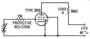
Fig. 5. Elementary thyratron configuration.
A 2050 thyratron has a maximum anode current rating of 0.5 ampere. If the grid bias is raised until the tube fires on the peak of the anode voltage, the anode load resistor must have a value of at least 306. This value follows from the fact that the drop across a 2050 is 8 volts during conduction, which makes the maximum applied anode potential 109 volts. In turn, the peak voltage at the firing point is 152.6 volts in this example. Since R = Ell, the series resistance must be not less than 306 ohms.
The anode could also be operated from a DC source, in which case the 2050 would conduct continuously (once it has been fired) , instead of conducting only on positive half -hzs from the AC source depicted in Fig. 5. When operated from a DC source, the 2050 is rated for 0.1 ampere anode current ; therefore, in this application, the series resistance must be chosen by Ohm's law to limit the anode current to 0.1 ampere, or less. The voltage drop from anode to cathode of the thyratron is the same during conduction, whether AC or DC voltage is employed.
Some thyratrons have lower ratings, and others have considerably higher ratings. In any case, a tube manual should be consulted and the tube operated within its maximum ratings.
Otherwise, its life expectancy will be decreased. Note that all mercury-vapor thyratrons require a brief warm-up time before voltage is applied to the anode-to prevent damage to the tube.
The mercury droplets in the tube must be sufficiently heated to form vapor before applying high voltage.
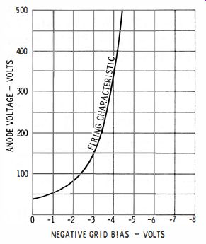
Fig. 6. Relation of grid bias and anode voltages to firing.
Extinction Voltage
No current flows in a thyratron until the grid and anode voltages permit the tube to fire (Fig. 6). At an anode potential of 150 volts, a typical thyratron will fire if the grid voltage is -3 volts. However, it will not fire at a grid voltage of -4 volts. Once the tube fires, the grid loses control, and conduction continues regardless of grid bias ; but the tube will stop conducting suddenly when the anode voltage is brought down to the extinction voltage. This anode extinction voltage might be zero, or slightly negative, depending upon the particular thyratron. Once the thyratron is thus deionized, the grid regains control.
It is clearly advantageous to employ AC anode voltage so that the anode is driven negative, insuring that the_ tube will de-ionize during the desired time. Test instruments that utilize on-off DC anode voltage for a thyratron commonly inject a small ripple voltage into the anode circuit so that a small negative extinction voltage is provided during the DC-off time.
TESTING NEON BULBS
The firing voltage of a neon bulb is readily measured with the test setup shown in Fig. 7. As the supply voltage is advanced, the voltmeter reading rises to the firing voltage and then suddenly falls back to the conduction voltage of the bulb.
The conduction voltage will rise slightly as the supply voltage is advanced further. However, the rated current of the bulb should not be exceeded during a check of conduction-voltage variation. The extinction voltage is less than the firing voltage.
A typical neon bulb fired at 75 volts, and then it fell back to 57.5-volts conduction drop. When the applied voltage was reduced to make the conduction voltage slightly less than 57.5 volts, the bulb was extinguished, and the voltmeter reading suddenly rose slightly (due to removal of the bulb current ). Various bulbs of the same type will vary appreciably in firing and extinction voltages. As the bulbs age, the critical voltages increase, and eventually a bulb will fail to fire at any reasonable value of applied voltage.
Oscilloscope Test
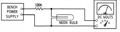
Fig. 7. Neon bulb firing voltage test.
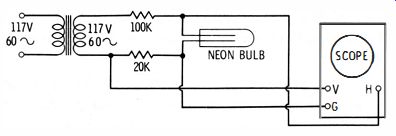
Fig. 8. Scope test of a neon bulb.
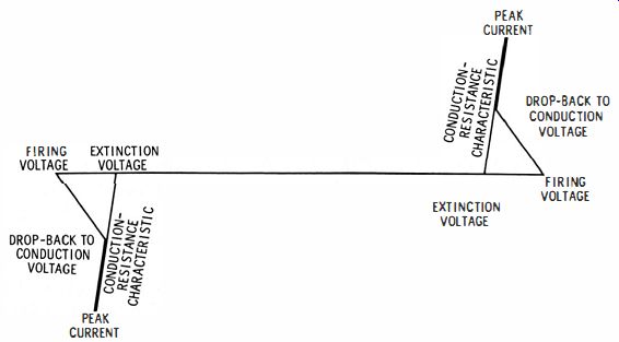
Fig. 9. Pattern obtained in the test of Fig. 8.
When bulbs are tested at quality-control positions, or on incoming inspection, an oscilloscope test provides faster and more complete test data. A suitable test setup is shown in Fig. 8. A 1:1 transformer is used to obtain isolation from ground.
An electrostatically shielded transformer is the best device to minimize possible spurious ground circulating currents. The voltage drop across the neon bulb produces horizontal deflection. The current flow (voltage drop across the 20K resistor) produces vertical deflection. If the vertical and horizontal channels are previously calibrated, voltage and current measurements can also be made from the screen pattern.
The resulting pattern for a good bulb is depicted in Fig. 9.
It shows that the bulb is a bilateral and symmetrical nonlinear resistance with discontinuities at the firing and extinction points. Now, if you advance the vertical and horizontal gain considerably, to expand the pattern in the region of the extinction voltage, you will see that the conduction-resistance characteristic is not quite linear but is slightly curved, as depicted in Fig. 6-10. In other words, the conduction resistance is not quite constant at different voltage drops across the bulb.
Note that the scope should have full response at 60 cycles without phase shift ; otherwise, the pattern will be distorted.
A DC scope is the best choice.
Pattern Looping
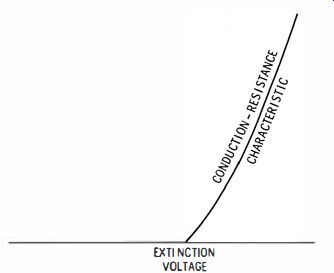
Fig. 10. The characteristics reveal. some nonlinearity.
Although it is not always recognized, a neon bulb has negative resistance over the striking interval of its characteristic.
Fig. 9 shows how the voltage drop across the bulb decreases or drops back after the critical firing voltage is passed. But although the voltage is decreasing, the current is increasing.
Ohm's law for this interval of the characteristic is written I = E/ -R. If the external circuit reactance is negligible, the negative-resistance interval is displayed as a straight line.
However, if the transformer in Fig. 8 has appreciable leakage reactance, the negative-resistance interval appears looped, as typically shown in Fig. 6-1 1. In this case the neon bulb oscillates briefly during the striking interval.
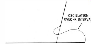
Fig. 11. Oscillation due to leakage reactance and distributed capacitance.
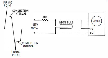
Fig. 12.
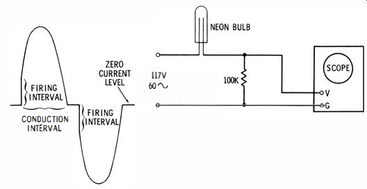
Fig. 13. Current flow …
Display on Linear Time Base
Neon bulbs can also be tested to determine whether they are within fixed limits by displaying voltage or current waveforms on a linear time base (sawtooth deflection ). For example, the test setup illustrated in Fig. 12 displays the voltage across the bulb versus time. If the vertical channel of the scope has been previously calibrated, the firing voltage can be measured, as well as the conduction voltage drop. Variation in internal resistance of the bulb over the conduction interval appears as a small curvature and a downward slope.
The test setup shown in Fig. 13 displays the current through the bulb versus time. A calibrated scope will show whether the current proportions and durations are within limits for a given type of neon bulb. It is clear that if the waveform in Fig. 12 applied to the horizontal channel of the scope, and the waveform in Fig. 13 is applied to the vertical channel of the scope, the pattern depicted in Fig. 9 results. Since the cyclo-gram of Fig. 9 displays both current and voltage information, it provides the most inclusive test.
TESTING VOLTAGE-REGULATOR TUBES
Service-type tube testers often provide a configuration, such as the one shown in Fig. 14, to check voltage-regulator tubes.
A variable DC voltage is applied to the tube in series with a current-limiting resistor. A voltmeter is connected across the tube. As the test voltage is increased, the meter reading rises until the critical firing voltage is reached. Then the pointer suddenly drops back on the scale. For example, if a VR tube fires at 110 volts, the pointer may drop back to 105 volts.
Next, the regulation of the tube is checked by increasing the current through the tube to rated maximum and observing the voltage drop across the tube. A typical VR tube varies less than 4 volts over its rated current range. This is basically a test of the conduction or dynamic resistance of the tube. A VR tube such as an OA3 has a normal dynamic resistance of 100 ohms or less. As a VR tube ages, the firing-voltage point raises, and its conduction-voltage level also increases. The regulating action becomes poor, due to increase of dynamic resistance.
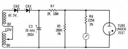
Fig. 14. A test circuit for VR lubes.
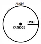
Fig. 15. Structure of a VR lube showing the anode probe.
As the tube symbol indicates (Fig. 14 ), the anode of a VR tube has a comparatively large area. The anode also has a probe projecting toward the cathode, as depicted in Fig. 15. These structural features affect the tube operation if the applied voltage is reversed. The tube has very poor regulation if the cathode is operated as an anode.
Oscilloscope Test
Quality-control or incoming-inspection tests of VR tubes are facilitated by oscilloscope tests. A typical test setup is shown in Fig. 16. A rectifier (M) is employed in order to apply the DC voltage in correct polarity to the VR tube. A bleeder resistor insures that leakage in the rectifier does not apply reverse voltage to the tube. If the vertical and horizontal channels of the scope have been previously calibrated, voltage and current values can be measured on the screen.
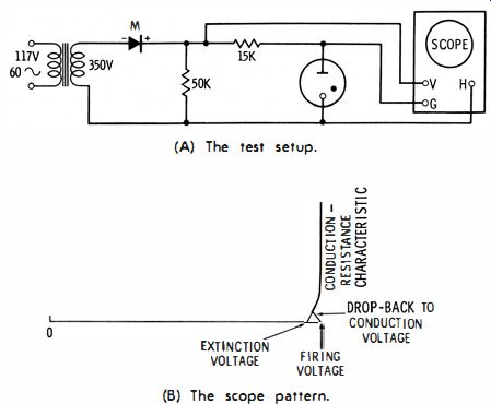
Fig. 16. Quality- control test for VR tubes.
The VR tube has a negative-resistance interval during the drop from firing to conduction voltage. Hence, the drop-back trace might have various shapes, depending on the leakage reactance of the transformer. The conduction resistance generally has a higher value near the start, but with increasing current the tube resistance then stabilizes at a constant, low value.
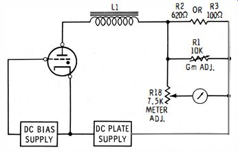
Fig. 17. Test circuit for a thyratron tube.
TESTING THYRATRON TUBES
Service-type tube testers usually check the grid-bias voltage level at which a thyratron fires, and the conduction voltage (arc drop) from anode to cathode. A milliammeter is connected in series with the anode lead, as shown in Fig. 17.
The tube is initially held beyond cutoff by a high negative grid bias. The bias voltage is reduced until the critical firing point is reached, as indicated by a sudden flow of anode current. There is a substantial tolerance for most thyratrons. At a 200-volt anode potential, a thyratron might be specified to fire at a grid bias between -2 and -6 volts, approximately. Fig. 18 illustrates the rated tolerance on firing voltage for a typical thyratron.
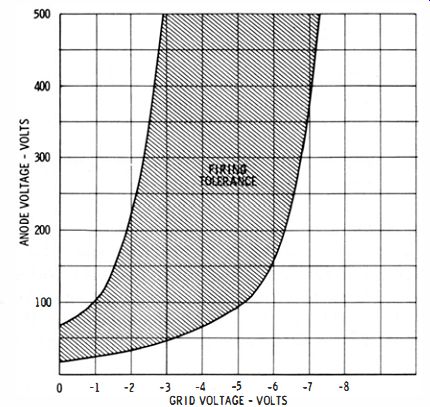
Fig. 18. Firing tolerance for a typical thyratron.
The second part of the test depicted in Fig. 17 is a measurement of anode current after the thyratron has fired. Since the tube normally has an extremely low conduction resistance, the current flow should be limited essentially by the anode circuit resistance only. Conversely, if the thyratron has abnormally high conduction resistance, this fact is indicated by a current reading lower than specified.
Oscilloscope Test
Failing thyratron tubes are easily detected with a scope test during routine maintenance procedures. Scope patterns provide more complete data than meter tests, as previously described. Practically all thyratrons in industrial equipment operate with AC anode voltage and when a scope is connected between anode and cathode of an operating thyratron, patterns are displayed as shown in Fig. 19. The most significant portion of the pattern is the arc-drop interval. If the tube is in good operating condition, and has adequate emission and correct gas pressure, without vapor contamination the thyratron will have a small and fiat arc drop. A failing tube has a comparatively high conduction resistance, which is displayed as a high and irregular arc-drop interval.
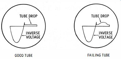
Fig. 19. Scope pattern, obtained in thyratron test.
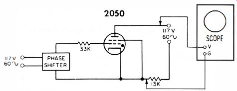
Fig. 20. A conduction angle scope test.
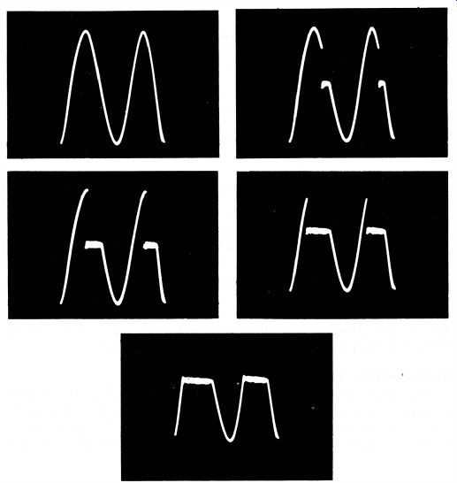
Fig. 21. Voltage waveforms from anode to cathode of a thyratron, showing
the conduction time for various phase relationship. between grid and plate
voltage.
Conduction Angle
The conduction angle of a thyratron can also be easily checked with a scope on an in-circuit test. Although the control grid in a thyratron tube has only "on" switching action, the phase of an AC grid voltage does control the average anode current. Fig. 20 shows a circuit in which the relative phases of grid and anode voltages determine the conduction angle, which varies from zero to 1800 as the grid phase-shifter is turned through its range. The phase shifter is often calibrated, and a scope test gives a check of thyratron response.
In Fig. 21, the anode-cathode voltage displayed in the first photo is a complete sine wave. There is no arc-drop interval (no anode-current flow)-the grid phase shifter has been adjusted so that the grid voltage is 180 0 out of phase with the anode voltage. In the remaining photos, the grid voltage is brought progressively into phase with the anode voltage, causing the conduction angle (arc-drop interval ) to increase accordingly. The average anode current increases as the arc-drop interval lengthens_ Note that the arc-drop intervals appear "fuzzy." This is a plasma oscillation, which is often observed in thyratron circuits.
The meaning of "conduction angle" is illustrated in Fig. 22, which shows the construction of a sine wave from a circle. The full circle contains 360° by definition. If you travel counterclockwise around the circle from zero and stop at p], you have gone 1/12 of the total circumference, or 30°. At point p] the vertical distance is half the maximum value. That is, the angle theta is 30° at Ph and the related sine wave has half its peak value. If you next proceed to point P2, you have gone 1/6 of the total circumference, or 60°. At point P2 the vertical distance is about 0.866 of the maximum value.
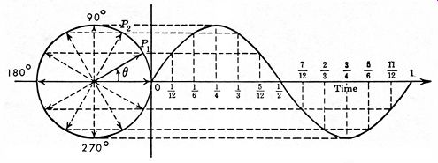
Fig. 22. Construction of sine wave based on angles of circle.
The conduction intervals of the various waveforms in Fig. 21 correspond to two different angles in the circle of Fig. 22. The conduction angle is simply the difference between these two values. For example, if the thyratron conducts from 80° to 100°, then its conduction angle is 20°. In other words, the tube conducts 1/18 of the total elapsed time.
Grid-Emission Test
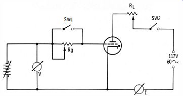
Fig. 23. Grid emission test of a thyratron. The grid current in a thyratron,
often referred to as grid emission, comprises current from the ionized space
charge to the grid, leakage current, and actual grid emission. A grid-current
test is made as depicted in Fig. 23. The tube is first warmed up thoroughly
with Sw1 and Sw2 closed. RL is adjusted for maximum-rated average plate current.
Then Rg is shorted, and the grid bias made more negative until the thyratron
stops conducting. The reading on V is noted, and may be designated as V1.
Next, Sw1 is opened and the grid bias adjusted to just stop conduction ; the reading on V again noted and this second reading is designated V2. If V 2 is not considerably higher than V repeat the test with a larger value of Rg. A value of 10 to 100 megohms will provide a substantial difference between V 2 and V1 for typical good thyratrons.
Since both readings were made with the tube at the cut-off point, the grid-cathode voltage is clearly the same in both tests. Hence, the difference between V2 and V1 is due to grid-current flow through Rg. By Ohm's law, the grid current is given by : Ig = (V2 - V1) f Rg. If the grid current exceeds the manufacturer's rating, the thyratron should be rejected.