AMAZON multi-meters discounts / AMAZON oscilloscope discounts
Nearly all the components discussed in the previous sections will be found in any one piece of electronic equipment.
In most cases, more than one of each will be included. Even so, it is exceedingly rare that such equipment can be constructed from those components alone. Instead, many other items are necessary for its operation.
Don't think that because they have been classified as "miscellaneous," the components to be discussed in this section are less important. This is not true. For instance, what good would a radio be without a speaker? The reason for the miscellaneous classification is that all the items in this section are not necessarily found in every piece of equipment.
ANTENNAS
No piece of transmitting or receiving equipment is complete without an antenna. At the transmitter, it is the final unit in the system. From it, the electromagnetic waves are "sent out" through the air to the receiver. Here, the antenna is the first unit in the system, intercepting these electro magnetic waves and conveying or coupling them to the input.
Sometimes the antenna is not an integral part of the equipment, but is mounted externally (on a roof, tower, etc.) . In such a case the antenna symbol may not be included on the schematic, but only the terminals where it is to be connected (see next section).
Symbols
Fig. 1 shows the symbols commonly employed for antennas. Symbols A, B, and C generally designate external antennas.
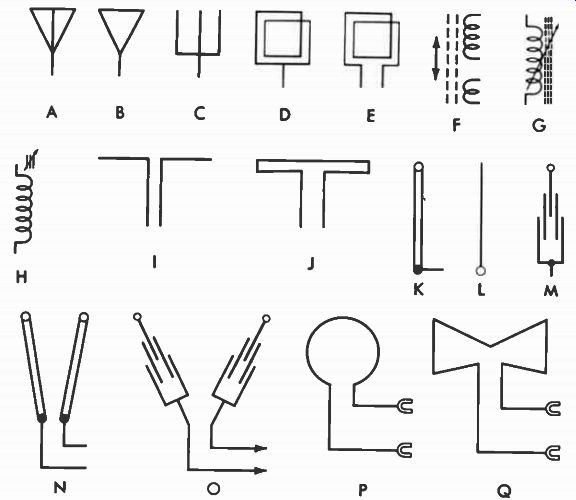
Fig. 1. Antenna symbols.
Two methods of depicting the familiar loop antenna are shown by D and E. (A loop antenna is a coiled length of wire usually fastened flat against the back of the cabinet.) Other versions of this symbol may be employed, but all will resemble this general layout. Another type of built-in antenna may use either symbol D, E, F, G, or H. This is called a ferrite-loop antenna (Fig. 2). It is actually a coil of wire wound around a ferrite core. Besides having the advantage of being very sensitive to weak signals, it is also tunable. The length of wire attached to the unit may be stretched out for additional pickup. Notice that symbols F, G, and H are the same as those for a coil, which this type of antenna actually is.
Methods of indicating TV antennas are shown by symbols I through O in Fig. 1. Symbol I is often used for any type, but actually represents a dipole-the basic TV antenna.
Symbol J is another basic TV antenna-the folded dipole.
The symbols at K, L, and M are for a monopole antenna (the single telescoping rod built into portable TV receivers) . The symbols at N and 0 are for the same type of antenna, except with two telescoping rods. A built-in UHF antenna is represented by the symbols at P and Q.
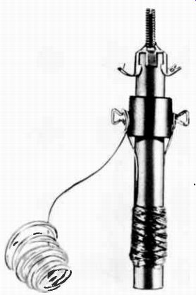
Fig. 2. A ferrite-loop antenna. Courtesy Stoncor Electronics, Inc.
Code Letters
Since all antennas-no matter how constructed-are so similar in function to a coil, many manufacturers use the letter L to designate them. Others prefer I or M.
SPEAKERS
The speaker is the final link in the chain of stages in a radio receiver or amplifier and in the sound system of a TV receiver. Its purpose is to convert the electrical signals, which vary in step with the sound to be reproduced, into the actual sounds.
A cutaway view showing the construction details of a typical 4-inch speaker is given in Fig. 3. The speaker operates as follows: The signal voltage is impressed across the voice-coil terminals and is carried from there to the voice coil by leads. Thus, a current which varies in step with the signal flows through the voice coil. A permanent magnet inside it interacts with the magnetic lines of force set up by the current. When the current flows in one direction, the voice coil moves backward along the magnet; and when current flows in the opposite direction, it moves forward. The voice coil is held over the magnet by a fiber disc called the spider, which is also connected to the cone. Therefore, as the voice coil moves, the cone does also, alternately expanding and compressing the air in front of it. Sound waves are nothing more than cycles of rarefied and compressed air, so the sound we hear is actually the disturbances produced by the cone.
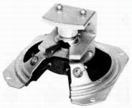
Fig. 3. Cutaway view of a speaker. Courtesy Quam Nichols Co.
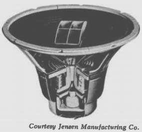
Fig. 4. A coaxial speaker. Courtesy Jensen Manufacturing Co.
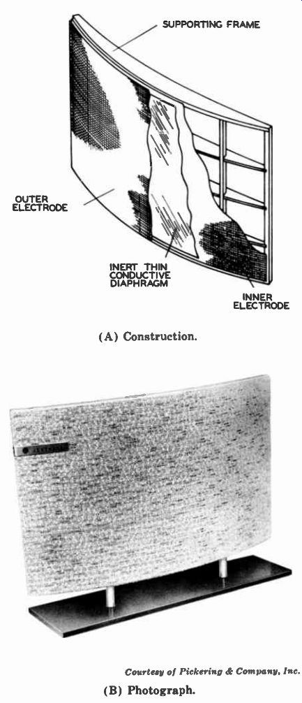
Fig. 5. An electrostatic speaker. OUTER ELECTRODE SUPPORTING FRAME INERT
THIN CONDUCTIVE DIAPHRAGM; INNER ELECTRODE (A) Construction. (B) Photograph.
Courtesy of Pickering & Company. Inc.
Another type, called a coaxial speaker, is pictured in Fig. 4. Actually, it is two speakers in one. The large cone around the outside reproduces the low frequencies, and the small cone in the center the high frequencies.
In another type of speaker, the permanent magnet is re placed by an electromagnet consisting of a coil of wire, called the field, wound around a soft-iron core. When a direct current flows through the coil, the core becomes magnetized, making the operation essentially the same as for the permanent-magnet speaker.
The construction of an electrostatic speaker is pictured in Fig. 5. As shown in Fig. 5A, it is composed of a thin plastic diaphragm, plus an electrode on either side, through which sound can pass. It is sometimes referred to as a capacitor-type speaker because of its construction. The two electrodes act as the plates of a capacitor, and when an audio signal is applied to them, its variations move the diaphragm accordingly and thereby produce the sound. Fig. 5B shows a commercial unit.
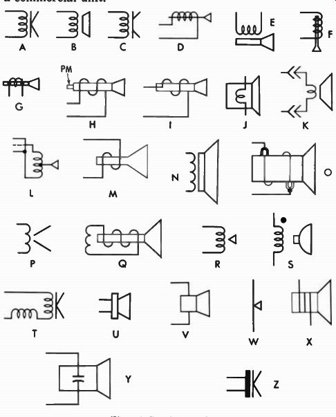
Fig. 6. Speaker symbols.
Symbols
Many different symbols are used for speakers, as shown in Fig. 6. Symbols A through S all show the voice coil and cone of a PM speaker. For an electromagnetic speaker, another winding called a hum-bucking coil will usually be added, as shown in symbol T. Its purpose is to cancel out any hum introduced by the speaker field. The field winding may be shown as a separate iron-core coil near the speaker symbol or elsewhere on the schematic.
Symbols L through X designate no particular speaker; they can be used for all types. Two symbols for indicating electrostatic speakers are given at Y and Z. There may be other variations, but all will resemble those for a PM speaker.
Sometimes the symbol for a single speaker is also used to depict the coaxial type of Fig. 4. At other times, two speaker symbols enclosed in a dashed-line box may be employed. Other minor variations of the symbols shown in Fig. 6 may be encountered; however, they will usually resemble those shown in this illustration.
Code Letters The letters S, SP, SPK, LS, E, and M are most commonly employed by the various companies to designate speakers.
FUSES
Unless some protection is provided, a short or other mal function could destroy an entire piece of electronic equipment. This protection is provided by fuses, some typical types being shown in Fig. 7. When a circuit draws too much current, the metal strip or wire inside the fuse melts, interrupting the excessive flow.
There are many types of fuses. The one at A in Fig. 7 is a 20-amp fast-acting type-the instant the current exceeds its rating, it will open. The slow-blow type B does not open if a momentary surge of current higher than its rating flows through it, unless the surge is prolonged.
The fuse at C is enclosed in a steatite instead of glass covering. The one at D has a rating of only .01 amp and is used to protect a meter circuit, while the one at E is designed to withstand the high vibration encountered in aircraft.
Other similar fuses have leads extending from their ends so they can be soldered directly into the circuit.
All the fuses in Fig. 7 are inserted into holders (Fig. 8; the item at the lower left is a fuse puller). Fig. 9 shows another type of fuse and its mounting. It is only 0.27 X 0.25 inch. The two leads fit into the matching holes in the holder and the cap is inserted over it.
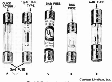
Fig. 7. Various sizes of fuses. Courtesy Littelfuse, Inc.
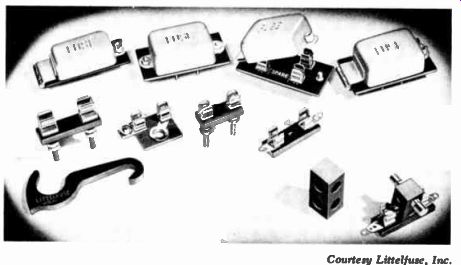
Fig. 8. Various types of fuse holders and a fuse puller.
Another type of fuse and holder is shown in Fig. 10.
Here, the fuse is twisted to lock it in place in the holder. The length of the fuse and the width of the locking tabs differ according to rating. Thus, the wrong size of fuse cannot be inserted.
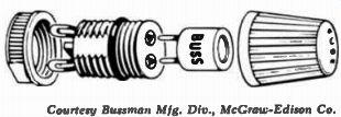
Fig. 9. A miniature plug-in fuse. Courtesy Bussman Mfg. Div., McGraw-Edison
Co.
Fuse Symbols
Symbols A and B in Fig. 11 are used by nearly every company to designate fuses. The only difference between the two is the addition of the circle in B to denote the terminals.
The symbol at C is sometimes used for a special type of fuse in which a chemical is used in place of a wire. Symbols D through H are all occasionally encountered. Symbol F is actually a drawing of the fuse, and G is a combination of A and F.
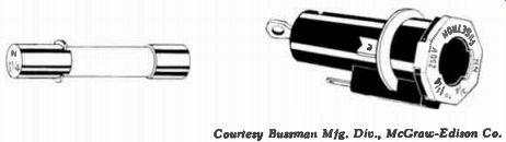
Fig. 10. An N-type fuse and its holder. Courtesy Bussman Mfg. Div., McGraw-Edison
Co.
Code Letters
Most companies designate fuses by the letter F on their schematics, although some prefer M or E. The rating usually appears on the schematic, alongside the fuse symbol and, if a slow-blow type, this fact will usually be noted, too.
CIRCUIT BREAKERS
The circuit breaker performs the same function as a fuse, but does not destroy itself in case of an overload. It merely opens two contacts, which are restored by pressing a button.
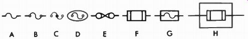
Fig. 11. Fuse symbols.
The circuit breakers in modern home electrical systems are a familiar application of this principle. Other circuit breakers are made for the small value of current in TV receivers or similar equipment.
There are two basic principles of operation for circuit breakers. In the thermal type, the current heats a metal strip which bends enough to open the contacts when the current reaches a predetermined value. When the strip cools, the contacts can be closed again by pushing the reset button. In the other type, an electromagnet (formed by a coil of wire) has sufficient strength to attract one of the contacts and open the circuit when the current reaches the prescribed limit.
Again, pushing the reset button closes the circuit. (However, it will open again if the overload still exists.) Some units combine the thermal and magnetic principles.
Symbols
Several symbols are used to represent circuit breakers.
The ones at A, B, C, and D in Fig. 12 denote both thermal and magnetic types. Symbol A is sometimes altered to show the method of operation. For example, adding a slant line to the curved portion of the symbol as in E indicates a switch-type breaker. Symbol F indicates a push-pull unit, and symbol G a push-push breaker.

Fig. 12. Circuit-breaker symbols.
The symbol for a thermal unit is given by H in Fig. 12.
It is a combination of symbol A and two partial circles which designate the thermal action. If the action is magnetic, the zigzag line in I is used instead. A coil and a switch symbol are combined to depict a magnetic circuit breaker in J, and resistor symbols are used in the thermal unit designated by symbols K and L.
Code Letters
The most common code letters for circuit breakers are CB, M, RC, and E. Sometimes the letter F is used, however. This is a carryover from the fuse which the breaker replaces.
LAMPS
Two types of lamps are generally employed for lighting the dials and other indicators in practically all types of electronic equipment. The first is a regular incandescent type similar to the common flashlight bulb. The other obtains its lighting properties from a rare gas, such as neon.
Incandescent Lamps
The incandescent lamp is always used where illumination, rather than a warning signal, is needed. For example, many radio and TV dials have lamps behind them to make the markings visible. In other equipment a lamp may be placed behind a jeweled bead which glows to indicate that the unit Fig. 13. Incandescent dial-lamp symbols. =0 0 A 8 is on. The symbols for dial lamps are given in Fig. 13. The circle depicts the glass envelope of the bulb; and the portion inside represents the wire, which gives off light when heated.
The letters I, B, F, M, P, PL, V, and E are used by the various companies to depict an incandescent lamp.
Neon Lamps
The neon lamp gives off only a soft red glow when lit. Its widest application, therefore, is as an indicator. It consists of two plates, called electrodes, separated by the neon gas.
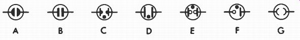
Fig. 14. Neon-lamp symbols.
The symbols for neon lamps (Fig. 14) all depict these two electrodes. The only difference is in the manner in which they are drawn and in the dot (which always symbolizes gas) inside the envelope. Symbol E is for AC lamps only, and symbol F is its DC counterpart. The same code letters designate neon as well as incandescent lamps. I, M, and B are the most common, however. Sometimes the letters NE (for neon) are also employed.
BATTERIES
Batteries power many types of portable equipment. Essentially, all batteries consist of two dissimilar materials in a solution-either plates immersed in an acid, as in the automobile storage battery; or a carbon rod and a zinc container with a solid material between them, as in a flashlight cell.
(A cell, often incorrectly called a battery, is the basic unit. A battery is two or more cells used together to provide the desired voltage or current. For example, a 12.6-volt storage battery contains six cells, each supplying 2.1 volts.)
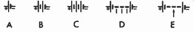
Fig. 15. Cell and battery symbols.
The two dissimilar plates form the symbol for a cell, as shown in A of Fig. 15. This symbol is practically universal in acceptance. The shorter bar represents the negative, and the longer bar the positive, plate. Often the "+" and "-" signs are also included on the symbol, as shown; sometimes only the plus sign is included.
Sets of bars are added to depict multi-cell units, as shown in B and C-but don't be misled into believing the number of pairs of bars always conforms to the actual number of cells in the battery. Sometimes they do, but usually no more than four or five sets of bars are employed, no matter how many cells they represent. Symbol D denotes a battery with taps at various points, and E a battery with a variable tap.
Such symbols are rather rare, however.
Letters B, BT, E, and M are the most common for identifying batteries on schematics.
CRYSTALS
Crystals are made from materials, such as quartz, which have the unique property of generating a voltage when pres sure is applied to them. Conversely, when an alternating volt- age is applied, they will bend or twist in synchronism with the variation. By cutting a crystal at various angles and to different dimensions, and by making electrical connections to it with a metal plate on each side (called a holder) , the crystal can be made to oscillate or vibrate at what is called its resonant frequency.
Once a crystal starts oscillating, only a very small force is required at the same frequency to obtain large-amplitude oscillations. These oscillations of alternating voltage are often connected to the grid circuit of a crystal-oscillator stage.
Since a crystal will oscillate at only one frequency (deter mined by its dimensions), the frequency of the crystal oscillator stage will remain constant.
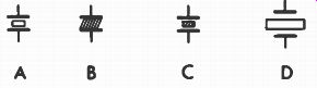
Fig. 16. Crystal symbols.
The symbols for a crystal in Fig. 16 illustrate its physical construction. The two bars represent the holder, and the rectangle or slanted lines, the crystal element.
The letters Q, Y, M, and X are used by various companies to identify crystals on their schematics.
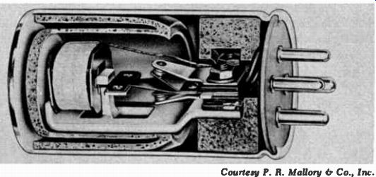
Fig. 17. Cutaway view of a typical vibrator. Courtesy P. R. Mallory & Co.,
In,.
VIBRATORS
In battery-operated equipment, the vacuum tubes some times require a much higher voltage than the battery can provide. The DC voltage cannot be stepped up by a transformer. Although not used much in present-day equipment, a vibrator (Fig. 17) formerly was commonly used to change the steady DC to a pulsating DC, which can then be stepped up by a transformer. The applied voltage is then rectified to change it back to a steady DC. When the battery voltage is applied to the vibrator (Fig. 17) , the coil at the top electromagnetically attracts the reed (the T-shaped element directly below it). When the reed moves, one pair of contacts near the bottom closes, shorting out the voltage to the coil at the top. With no force to hold it, the reed springs back, closing the other set of contacts and allowing current to flow through them. This action opens the first set of contacts, re-energizing the coil, and the cycle is repeated. This is how the vibrator contacts continuously interrupt the flow of current through the primary winding of an accompanying power transformer.
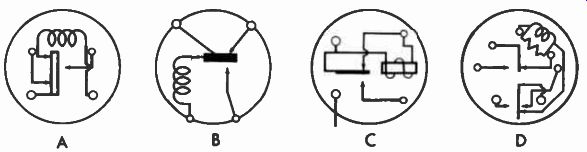
Fig. 18. Vibrator symbols.
The symbols for vibrators are merely representations of the connections within the unit. Fig. 18 shows some examples. About the only difference in the symbols is that some times the pins (indicated by circles) are shown within the outer circumference in the same arrangement as they appear on the actual vibrator, and at other times are placed around the outside. Symbols A and B show these two methods, the conventional coil symbol being used in both. Another method is employed in C. Here, the contacts are represented by the arrowheads, and the vibrating reed by the heavy bar. The connections within different vibrators may vary consider ably. Only four of the many combinations are illustrated in Fig. 18. The only difference among the other types will be in the number of contacts and in the connection of the components within the unit.
Vibrators are identified by the letters V, E, G, VB, and M on the schematics of most companies.
MICROPHONES
Sound waves, as they exist, cannot be boosted in strength. Nor can they be mixed directly with the signal at a radio station and transmitted over the airwaves. True, a mega-phone can direct the sound to a certain point, but the total power contained will not be increased.
Before sound waves can be amplified, they must be changed into an electrical signal. This signal can then be put to a number of uses-it can be boosted in strength by an amplifier and converted back to sound by a speaker, mixed with the radio or TV station signal (called "modulating") , applied to the head of a tape recorder to record the signal on tape, etc.
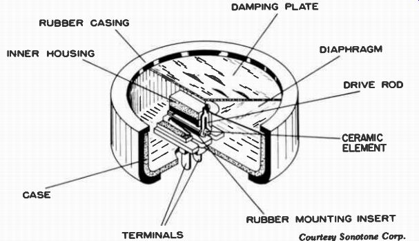
Fig. 19. Construction details of a ceramic microphone. DAMPING PLATE RUBBER
CASING INNER HOUSING DIAPHRAGM DRIVE ROD CASE TERMINALS CERAMIC ELEMENT RUBBER
MOUNTING INSERT. Courtesy Sonotone Corp.
A microphone changes sound waves into a varying electrical signal. Thus, its purpose is just the opposite from that of the speaker discussed earlier in this section. A speaker, however, will work as a microphone. Most intercom systems use a conventional speaker which, by proper switching, also acts as a microphone.
One type of microphone employs a coil which moves in a magnetic field and thereby converts sound into electrical waves. As the sound waves strike the diaphragm, the coil movement induces a voltage in the coil. Such microphones are called dynamic or moving-coil types.
Several other principles are used for microphones. The carbon type consists of a brass cup filled with compressed carbon granules. A diaphragm connected to the cup is moved back and forth by the sound waves. The movement changes the pressure on the granules and hence the resistance of the carbon to the flow of current through it. Another microphone operates on the capacitor principle-the sound waves E move a plate back and forth with respect to a fixed plate and thereby change the capacitance.
Fig. 19 shows the construction of a ceramic microphone.
Here the sound enters the louvered plate at the top and strikes the diaphragm, moving it back and forth. The ceramic element (barium titanate), connected to the diaphragm by the drive rod, exhibits properties similar to those of the crystal discussed earlier in this section. That is, as the pres sure of the sound waves bends the ceramic unit, a voltage is generated. The resulting current is transferred, via the terminal at the bottom, to the amplifier. The unit shown in Fig. 19 is enclosed in a housing for protection.
Some microphones employ crystals (Rochelle salts are the most common) instead of the ceramic elements. However, they are more susceptible to damage by high temperatures and humidity than the ceramic units.
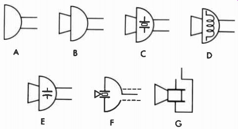
Fig. 20. Microphone symbols.
The most common symbols for a microphone are shown in A and B of Fig. 20. When these symbols are used, the type (crystal, magnetic, etc.), is usually designated by a note beside the symbol. Symbols C, D, and E represent crystal (ceramic), dynamic, and capacitor microphones, respectively. In F and G are shown two methods of combining a standard microphone symbol with the symbol showing the type (in this example, crystal or ceramic). Similar versions are sometimes used for other types of microphones. The microphone symbol is often omitted from schematics because it usually is not an integral part of the unit. Instead, only the terminals to which it is connected are shown.
The letters M, MIC, or E are the most popular for microphones. Often, no code letter is used. Instead, the type of microphone is written out beside the symbol.
TRANSDUCERS
The microphones described in the preceding are designed to pick up sounds that we can hear and convert them to electrical waves. Other devices are very similar, but are designed to respond to sounds we cannot hear. A common example of this application is the use of ultrasonic sounds for remote control of a television receiver. In this application the unit is called a transducer, or ultrasonic microphone. (Actually the term "transducer" describes any device for transferring the flow of energy from one or more systems to one or more other systems. Thus, a speaker is also a transducer; a sonar pickup is another transducer. The application of the term "transducer" to ultrasonics is quite common, however.) Fig. 21 shows some of the symbols used to depict ultrasonic transducers. As with microphones, many materials are used for construction. The type may be designated by a note be side the symbol.
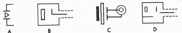
Fig. 21. Ultrasonic-transducer symbols.
HEADSETS AND EARPHONES
Like the speakers discussed previously, the headset or earphones convert a varying voltage into sound. Some of them are constructed much like a speaker. Usually, two coils are placed over two pole pieces which are permanent magnets.
These pole pieces attract a metal diaphragm suspended over them. As the current through the coils varies, the magnetic field it sets up is alternately added to and subtracted from the field of the permanent magnets. This changing field moves the diaphragm back and forth in step with the voltage.
Other types of headsets have crystal or ceramic elements.
They operate like the microphone discussed previously, except in reverse. That is, a varying voltage is applied to the crystal or ceramic slab, which in turn moves the diaphragm back and forth.
The two basic symbols for headsets and earphones are given by A and B in Fig. 22. Symbol C is for a double headset. Additional circles are sometimes placed inside the symbol, as shown by D. Symbols E and F, a combination of those in Fig. 20 and A in Fig. 22, designate a handset (a combination microphone and earphone) used in telephone and some intercom systems.
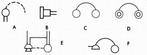
Fig. 22. Earphone, headphone, and handset symbols.
PHONO PICKUPS
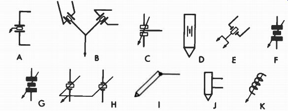
Fig. 23. Phono-cartridge symbols.
The phono cartridge converts into electrical signals the vibrations produced by the variations in a record groove.
It bears a close resemblance to the microphone, where the variations in sound waves are converted into electrical signals. Many symbols have been devised for depicting the phono cartridge. Since some are monaural and others are for stereo, and since some have one needle and others two, differences in indicating them are inevitable. Symbols A and B in Fig. 23 are similar except that B represents a stereo cartridge. Two crystal elements are shown, but only one needle. Other ways of indicating crystal or ceramic cartridges are given by C through H. The symbols at G and H are for stereo cartridges, while a magnetic cartridge is symbolized by K. Symbol D can also be made to signify a magnetic pickup by substituting a coil symbol for the crystal symbol on its body. Usually, when a pickup is not an integral part of the actual circuit, no symbol is used; instead, a socket into which it connects is shown on the schematic. In place of the code letter, an identifying note is often placed beside the symbol for a pickup. When employed, the letters M, P, and PU are the most popular.
TAPE HEADS
In a magnetic tape recorder the heads perform three functions. The first function is essentially the same as that of the phono pickup. The head converts the variations in the recording to an electrical signal which corresponds to the sound that has been recorded. This electrical signal is then amplified before it is applied to a speaker, where the electrical signal is converted to sound. The difference between a tape head and a phono pickup is that on a phonograph record, variations are cut in the groove to correspond to the signal. In a tape recorder, a varying magnetic field is applied to the tape which holds this magnetic pattern. As the tape passes the head, a signal is developed in the head circuit which varies in step with the signal originally used to magnetize the tape.
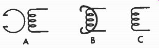
Fig. 24. Magnetic-head symbols.
The second function provided by magnetic heads is to re cord the signal on the tape. Essentially this is the reverse of the pickup. Here the signal is applied to the head. As the tape passes the head a varying magnetic field is set up in the tape corresponding to this signal. Often the same head is used for recording and playback, and the connections to the head are changed by a switching arrangement.
The third function of heads is erasing. Magnetic tape can be used over and over. Once a pattern is recorded on the tape, it will remain on the tape until it is erased by bringing it in contact with a magnetic field. This magnetic field can be DC or a high-frequency AC, but the AC is more common. Most tape recorders have a head which contacts the tape just ahead of the recording head. Called the erase head, it re moves any signal on the tape just before the new signal is recorded. During playback, no signal is applied to this head so the signal will not be removed. Fig. 24 shows the symbols for tape-recording heads. The ones at A and B show a combination of a coil and a circular element. This is similar to the actual construction of a magnetic head, as shown in the photo of Fig. 25. A coil is sometimes used by itself to show a magnetic head. Usually a note will be placed by the symbol to explain its function. The symbols at A and B in Fig. 24 will usually have an R (record), P (playback), or E (erase) inside the circular portion. If the head is used for both recording and playback, an RIP will be used.
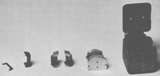
Fig. 25. Magnetic heads.
ROTATING MACHINES
Although not classed as electronic equipment, motors, generators, dynamotors, etc., are sometimes included on schematic diagrams. Phonographs, tape recorders, and fans are examples of equipment using motors.
Motors
The basic symbol for a motor is an M, the letters MOT, or the word MOTOR placed either alongside or inside a circle, as shown by A in Fig. 26.
Where it is desirable to show the connections to the motor, symbols B and C may be used. In symbol B, the field coil is in series with the armature, while symbol C shows it in parallel. (The coil symbol depicts the field, and the circle the armature.) Two methods of showing phonograph motors are illustrated by symbols D and E. Some other representative methods are depicted in F through J. In each instance, the symbol is drawn to conform with the motor connections.
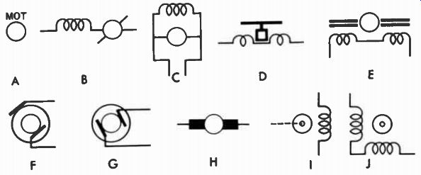
Fig. 26. Motor symbols.
Generators
In general, symbols for generators are the same as for motors, except the letter G, the letters GEN, or the word GENERATOR will be used, of course.
Dynamotors
Dynamotors are sometimes used in communications equipment to step up a low DC voltage. They are made up of a DC motor and generator with a single field winding and a common armature, but separate commutators. The symbols resemble those for motors and generators, as shown by the two representative symbols in Fig. 27.
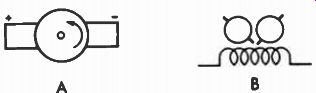
Fig. 27. Dynamotor symbols 00
SOLENOIDS
A solenoid is an electrical device which provides some mechanical action, such as closing a valve or sounding a door chime, when a voltage source is connected to it (by pushing a button, for example) . A solenoid consists of a coil surrounding a movable iron core attached to a spring. When current flows through the coil, the core is either attracted farther into or repelled partially from it. The movement of the core actuates the de vice to which it is connected. When the current through the coil ceases, the spring returns the core to its original position.
As you have probably guessed, the symbol for a solenoid is like that for a coil with a core, as shown by A and B in Fig. 28. An arrow will sometimes be added, as shown in C, D, and E, to depict the fact that the core is movable.
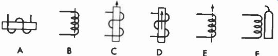
Fig. 28. Solenoid symbols.
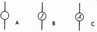
Fig. 29. Meter symbols.
METERS
Meters are sometimes included in electronic equipment so that operating conditions or other information can be monitored. They are often depicted by symbol A in Fig. 29, ac companied by identifying letters inside or alongside it. An arrow may be added to indicate the pointer, as shown by symbols B and C. The same identifying letters are used, but only alongside the symbol, of course.
The most common abbreviations for identifying the type of meter are:
- A-ammeter
- AH-ampere-hour meter
- CRO-oscilloscope
- D-demand meter
- DB-decibel meter
- F-frequency meter
- G-galvanometer
- I-indicating meter
- M-integrating meter
- MA-microammeter
- NM-noise meter
- OHM-ohmmeter
- PH-phase-meter
- PI--position indicator
- PF-power-factor meter
- REC-recording meter
- S-synchroscope
- TLM-telemeter
- V-voltmeter
- VA-volt-ammeter
- VI-volume indicator
- VU-volume-unit meter
- W-wattmeter
- WH-watt-hour meter
OTHER SYMBOLS
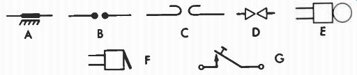
Fig. 30. Miscellaneous component symbols.
Up to this point we have discussed practically every component used in electronic equipment. Fig. 30 illustrates the symbols used for some items which will occasionally be found, particularly in specialized equipment. Symbol A is for a spark plate used in automobile radios. It consists of a metal plate placed alongside the chassis and separated by an insulating material. Three methods of depicting lightning arresters are shown by B, C, and D. Symbol E is for a bell, while F depicts a buzzer. Symbol G is for a telegraph key.
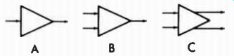
Fig. 31. Amplifier symbols.
A manufacturer will sometimes want to show a drawing of a large installation, but not every circuit component. On this type of diagram, an entire amplifier is indicated by a triangle, as shown by A in Fig. 31. For more complicated circuits, two inputs and a single output will be shown as in B, or two inputs and two outputs as in C.
QUESTIONS
1. What is the purpose of a speaker?
2. What circuit element destroys itself when it performs its intended purpose?
3. What are the two types of lamps used in entertainment type equipment?
4. What is the difference between a cell and a battery?
5. Name three types of microphones.
6. Draw the symbol for a headset.
7. Draw the symbol for a voltmeter.
8. Draw the symbol for a crystal.
9. Draw a battery symbol and indicate the polarity.
10. What does this symbol indicate?