AMAZON multi-meters discounts / AMAZON oscilloscope discounts
All components are useless unless they can be interconnected. There are many ways to do this. One-the printed circuit-was a contributing factor in the development of the "personal-sized" transistor radio discussed earlier.
WIRES
The most widely known method of connection, of course, is by means of a wire. It can be an actual wire run between two points, or the wire (more commonly called lead) of a component. Nevertheless, the two are indicated in the same way on the schematic.
As you probably know, a line denotes a wire or a component lead. There are three methods of showing whether two leads are connected or not. The first is illustrated by A in Fig. 1.
The vertical line at the left intersects the horizontal line, indicating in this system that they are connected. Now notice that the lead at the right has a half-circle at the crossover point. The half-circle means that this wire (called a jumper) bypasses the horizontal line.
In the system at B, the dot placed at the point where the left vertical line crosses the horizontal denotes that the two lines are connected. Conversely, no dot at the intersection of the right vertical and the horizontal lines indicates no connection.
These two systems can be confusing if you don't know off hand which one is being used. In A, two crossed lines indicate a connection, whereas in B, they indicate just the opposite.
For this reason, it is always best to carefully study the schematic first. If jumpers are used at some places, you know that the crossed lines indicate a connection. Dots at the point where some lines cross alert you to the fact that lines crossing without dots do not connect. The system at C in Fig. 1, actually a combination of the two previous systems, eliminates any chance of confusion. The dot (at the left) indicates that the two lines connect. To be on the safe side, the jumper (at the right) is also used to indicate no connection.
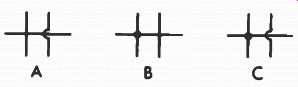
Fig. 1. Three methods of showing connecting and non-connecting leads.
GROUND AND CHASSIS SYMBOLS
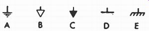
Fig. 2. Ground and chassis symbols.
Three other symbols often seen on schematics are given in Fig. 2. Those at A, B, C, and D are referred to as ground symbols. Actually, the term "ground" is a carryover from the early days of radio, when the receiver was literally connected to the earth (ground). The term "earth" is used in British terminology to describe this point. Today, the more popular symbol A designates a common-return point for all circuits. Otherwise, a line would have to be drawn to all of them. Imagine how cluttered up the schematic would be! All points exhibiting this symbol are considered connected.
Often, the ground symbol signifies the chassis of the equipment. Instead of the various points being connected by a wire, they are merely connected to the metal chassis. This is true except in AC/DC equipment, where doing so would necessitate connecting the chassis to one side of the power line. This would make the chassis "hot"; anyone touching it would receive a shock. In this type of circuit, the chassis is designated by the symbol at E in Fig. 2.
Sometimes, particularly in high-fidelity equipment, a heavy copper conductor called a "bus bar" will be positioned near several stages and connected to ground. All circuits are then returned to ground through it instead of directly to the chassis. The advantage of such an arrangement is reduced hum. The bus bar may be indicated on the schematic by an extra heavy line.
OTHER METHODS OF DENOTING CONNECTIONS
Companies are constantly striving to make their schematics easier to read. A long, winding line is most difficult to follow around a schematic when the connections are remote and widely separated. Eliminating as many lines as possible is one way to simplify a schematic. For example, instead of drawing them from the voltage sources in a power supply to their destinations, an arrangement like that in A of Fig. 3 can be used. Each source is indicated by a dot and labeled with the voltage available at that point. Then, all other points connected to this source are indicated by an arrow accompanied by the available voltage, as shown at B.
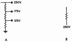
Fig. 3. A common method of showing connections to voltage sources.
Instead of the arrow in Fig. 3, a circle of the same diameter as the dots in the power supply is sometimes substituted.
Coded letters such as A, B, and C occasionally are used instead of listing the actual voltage.
Some companies employ triangles, squares, diamonds, and other geometric designs to signify connection between two points. Usually, the source is indicated by a solid-colored symbol, and the points connected to it by the outline of that symbol.
Similar methods have been adopted for designating connections between points other than voltage sources. Usually, letters are employed--all points labeled with the same letter are assumed to be connected.
Sometimes two points are interconnected by a cable (several wires bundled together), usually designated by symbol A in Fig. 4. The ring surrounding all wires represents the outer covering of the cable, and may be placed at each end or in the center. If the cable is shielded, a ground symbol may be added to the symbol at A, as shown at B. Also, a dashed circle may be used, or a dashed line above and below the lines representing the wires, as shown at C and D. A ground symbol will be connected to the dashed lines, as shown at C and D. The same systems are also used for designating a single shielded lead, as shown by symbols E, F, and G. The dashed lines at G may extend the entire length of the cable or wire, or for only a short distance as shown here.
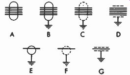
Fig. 4. Cable and shielded lead symbols.
CONNECTING DEVICES
Sockets, plugs, and jacks are only a few of the many types of connectors. All have one thing in common-a convenient means for connecting and disconnecting two points. Imagine the problem every housewife would face if her toaster had no plug and she had to fasten the leads to the wall outlet every morning?
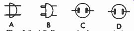
Fig. 5. AC line-cord plug symbols.
The symbol for connectors is usually an actual drawing.
Symbols A, B, and C in Fig. 5 are good examples; A and B are side views and C is an end view. Symbol D is for a socket.
The symbol for a pronged unit (plug) is solid-colored, and A hollow for the open unit (the socket). The same system is used for most plug-and-socket combinations. Fig. 6 depicts only a few of them. In each instance, the symbols show the actual arrangement of the plug pins or socket openings.
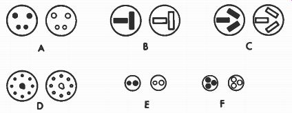
Fig. 6. Plug and socket symbols.
Fig. 7 illustrates five methods of showing connections for single leads. Symbols A and B are for the familiar phono-type plug and socket found on the rear of many radio and TV receivers. Symbols C, D, and E all depict simple one-wire connectors. The arrow head in symbol C is the plug and the remainder is the socket. Symbols D and E use the same solid and hollow representation explained before.
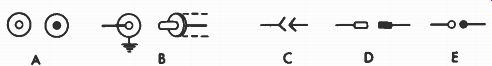
Fig. 7. Single-wire connector symbols.
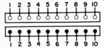
Fig. 8. One method of symbolizing multiple-contact plugs and sockets.
If the socket and plug contain so many connections that it would be difficult to show leads from all the pins, a different method is sometimes used. The various points may be arranged in a row and each pin and socket terminal numbered, as shown in Fig. 8. A separate drawing showing the pin to numbering and arrangement is usually included on the schematic also. Instead of the arrangement of Fig. 8, individual connections may be shown, as in C, D, and E of Fig. 7. Each is then labeled with the plug or socket number, followed by a dash and a number denoting the pin. Most of the time, plugs and sockets are not identified by code letters. When they are, the letters P or PL (for plug) and S or SK (for socket) , or X and M are the most popular.
Terminals for the antenna, speaker, etc., connections must also be shown on schematics. Fig. 9 shows some of the more common designations.
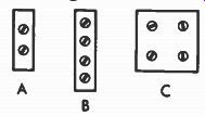
Fig. 9. Terminal symbols. Courtesy Switchcraft, Inc.
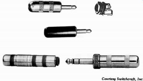
Fig. 10. Typical plugs and jacks.
Jacks and their matching plugs (Fig. 10) are also used in many types of equipment, usually to make or break connections as the plug is inserted. Fig. 11 shows some typical symbols for jacks of this type. (The arrow shown with symbol A indicates the direction in which the plug is inserted, but is not a part of the symbol.) When inserted, the tip of the plug is connected to the upper terminal in symbol A. In B, the plug strikes the V-shaped portion connected to the upper terminal, forcing it up and disconnecting it from the center terminal. As before, contact is made between the upper terminal and the plug. Sometimes the plug will cause a contact to be made instead of broken, as in symbol C. Many other combinations are possible, as shown by symbols D through G.
The symbols showing two V-shaped elements indicate a jack with two separate connectors contacting two points of the plug. Both points are normally insulated from each other.
For example, one may be on the tip of the plug, and the second on another portion called the ring.
The cross-hatched pattern of the symbol at F signifies that the two points to which they are attached are joined mechanically but not electrically. All the symbols in Fig. 11 show a bar or rectangle at the front depicting that portion of the jack (called the sleeve) which extends out of the chassis, and into which the plug is inserted. This area will sometimes be shown as a heavy solid bar.
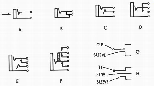
Fig. 11. Symbols for various types of jacks and plugs.
The symbols at G and H in Fig. 11 are for plugs. The one at G is for a two-conductor plug, and the one at H is for a three-conductor plug.
Like sockets, jacks and plugs are usually not assigned code letters. But if they are, the letter J is the most popular for jacks, and P or PL for plugs, although X and M may some times be employed.
PRINTED CIRCUITS
In many types of modern electronic equipment, the wiring has been replaced by a printed circuit. Appropriately named, a printed-circuit board comprises a phenolic base onto which the conductors are embossed with a conductive paint. Its biggest advantage is that tedious hand wiring is no longer necessary. Instead, the circuits can be mass produced by machines, a process which is not only quicker but also more reliable.
Compactness in equipment design is another virtue of printed circuitry.
On the debit side, a printed-circuit board is easily broken, often beyond repair. Nevertheless, its use has mushroomed in the past decade. The connections made by the printed wiring are shown in exactly the same manner as with hand wiring. If only part of the circuit is printed, that portion may be outlined by a dashed line and identified as such.
Ways of identifying the different points of the printed wiring board will be discussed later.
COMPONENT COMBINATIONS
Two or more components are often contained within a single unit. This is done to save space, cut costs, and prevent interaction between components (thus forestalling a mal function) .
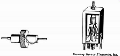
Fig. 12. Component combinations. (A) A resistor and coil. Courtesy Stancor Electronics,
Inc. (B) A transformer with capacitors connected across each winding.
Coil and Transformer Combinations
Various combinations of components are employed. For example, a coil may be wound directly over a resistor, as shown in Fig. 12A. Or a capacitor may be connected across one or both windings of a transformer, as shown in Fig. 12B. The schematic representations for these two units, as well as other popular combinations, are given in Fig. 13.
The symbols may be enclosed in a dashed-line box which signifies that all components within it are part of an individual combination unit. Notice the ground symbol connected to the box in C-it indicates that the components within the box are shielded from the rest of the circuit. That is, stray magnetic fields cannot enter or leave the box. This shielding is provided by a metal cover (or can as it is more commonly called) which touches the chassis and is thus grounded to it.
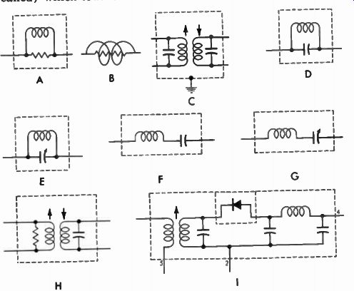
Fig. 13. Various coil and transformer combination symbols.
Some of the other combinations are also given in Fig. 13.
The units represented by symbols D, E, F, and G all contain a coil and capacitor. Symbol D has a fixed capacitor connected directly across a coil. In symbol E, the coil is also in parallel but with a variable capacitor. The coils and capacitors in F and G are connected in series.
The transformer in symbol H has a resistor connected across one winding and a capacitor across the other. Many other similar combinations are possible. Symbol I represents a transformer, three capacitors, a coil, and a crystal diode- all occupying a single can. Notice that the dashed lines extend all the way around the crystal diode, signifying that the diode itself is entirely enclosed by a separate can. Usually the diode is mounted in two clips on top of the regular can, over which a metal cover is placed to shield the diode.
This same dashed-line symbol with the ground connected to it is used in many ways to designate a shield. As mentioned previously, when drawn around a lead or group of leads, it represents a shielded wire or cable. At other times, it may be placed around a tube symbol on a schematic to denote that a shield is placed over the tube after it has been inserted into its socket.
The various companies differ considerably in the code letters by which the foregoing units are designated. Some assign the same L or T that they do for a regular coil or transformer, but leave the resistors and capacitors unassigned. If more than one coil is included, they are subclassified with an A, B, C, etc. Other companies assign code letters to the individual components just as if they were separate units.
Packaged Electronic Circuits
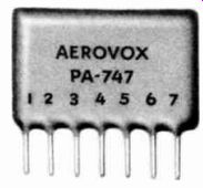
Fig. 14. A packaged electronic circuit. Courtesy of Aerovox Corporation.
Another unit which includes several individual components is pictured in Fig. 14. These contain various combinations of resistors, capacitors, and in some instances, coils, all bound to a base plate and sealed with a protective coating. Such units are extremely resistant to moisture, temperature, and shock. Fig. 15 should give you an idea of the time and space saved by using these devices. All the components on the left are contained within the single unit on the right. By using this unit, nine soldered connections are eliminated and only one-sixth of the space is required. This unit has nine external leads and contains all the components necessary for coupling between two stages of a radio receiver.
These units are usually represented schematically by using regular resistor and capacitor symbols. The combination is then enclosed within dashed lines to indicate they are contained in a single unit. Each lead is numbered at the point where it extends from the dashed lines.
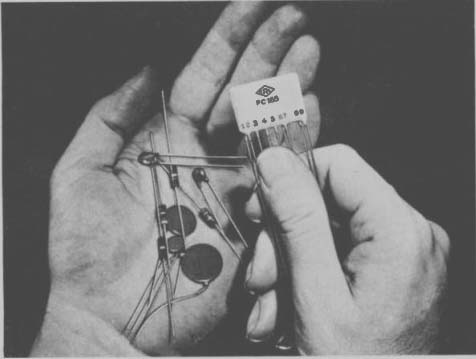
Fig. 15. A packaged electronic circuit and the components it replaces. Courtesy
Centrolab, Electronics Div. of Globe-Union Inc.
There are myriad units employing this type of construction. Each will vary only in the number of components, their connection, or their value. Fig. 16 A through G shows some of the available combinations.
The dashed lines around the components in the unit are sometimes omitted. Occasionally, the symbol at H in Fig. 16 may be used, and it may or may not be enclosed within dashed lines. The internal connection is usually shown else where on the schematic.
There are several methods of assigning code letters to these packaged units. Some companies will assign one code letter (A, E, K, M, N, X, PC, PN, DC, or RC) to the entire unit. Others will assign the letters R and C to the unit, and designate the individual components as A, 13, C, etc. Still others may combine the two methods, assigning a code letter and a number to the entire unit and then designating the components within the regular R and C designations.
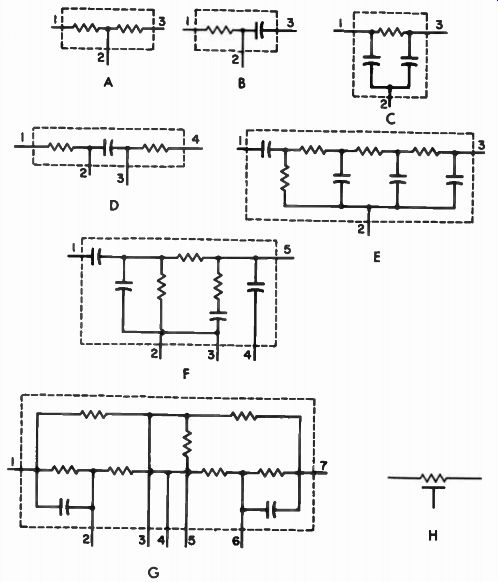
Fig. 16. Packaged electronic-circuit symbols.
Integrated Circuits
The latest development in the combining and miniaturization of components is being pointed out in the photo of Fig. 17. The integrated circuit is actually a specially constructed semiconductor device. The unit in Fig. 17 per forms the functions which would require 26 separate conventional components (one coil, two transistors, two diodes, seven capacitors, and fourteen resistors.) Here it is housed in a conventional transistor case; it could be placed in a much smaller unit, except it would be too small for ease of handling and attaching leads.
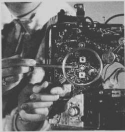
Fig. 17. An integrated circuit installed in a television receiver. Courtesy
Radio Corporation of America (RCA).
The actual equivalent circuit of the integrated circuit may be shown on a schematic and enclosed in dashed lines, as shown in Fig. 18. (Notice that while the unit in Fig. 17 replaces 26 conventional components, the equivalent circuit contains many more components.) Usually, however, a tri angular or rectangular symbol (Fig. 19) will be shown on the schematic to represent the integrated circuit. Terminals are added to these symbols to connect the various external connections. Then the equivalent circuit will usually be included elsewhere.
Courtesy Radio Corporation of America
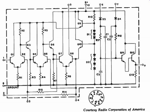
Fig. 18. Equivalent circuit of the
integrated circuit in Fig. 17.
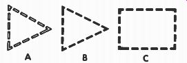
Fig. 19. Integrated-circuit symbols.
QUESTIONS
1. Why is it advantageous to show all voltage sources together and then indicate the points which connect to them ?
2. Does a symbol which has a solid black dot depict the socket or the plug portion of the unit?
3. Are the terms "ground" and "chassis" synonymous?
4. What does a heavy line connected to ground indicate?
5. How are printed circuits shown in schematics?
6. Name two advantages of using component combinations.
7. What does a dashed line around a component (or group of components) with a ground symbol connected to it indicate?
8. What does the letter A or B following the code letter and number of a component usually indicate?
9. Show two methods of illustrating crossing wires which are not connected.
10. Show two ways of depicting an AC line-cord plug.