5. Digital Magnetic Recording
The information in this section on digital magnetic recording is presented as an attempt to document a bit of audio history. It is very likely that by the time the next edition is published, all recording will be performed in RAM or other solid state memory, and magnetic recording both analog and digital will be of historical interest only. As of this publication there is a clear trend toward digital audio workstations as being the standard recording devices, with the audio stored on hard drives. Tape-based systems are virtually gone.
Currently, computers exist which utilize flash memory, and as such have no moving parts at all. At the moment these computers are expensive and have relatively low capacity compared to conventional hard-disk-based computers, but they are clearly the wave of the future.
5.1 Longitudinal Digital Tape Transports
Longitudinal digital tape recorders came in many varieties, the most successful were the DASH and ProDigi formats. DASH is an acronym for Digital Audio Stationary Head. The tape transports for these recorders were very similar to any high-quality analog mastering machine, but the very high density of very narrow tracks required extremely accurate tape guiding and head placement. For example, the DASH format with 52 tracks across a ½ inch tape specified head height to 0.6 mils (0.015 mm) and a guide placement to 0.2 mils (0.005 mm).
Tape speeds for multitrack DASH and ProDigi machines was 30 in/s for normal 48 kHz sampling of 16 bit data, but the DASH high resolution (HR) upgrade boosted the speed to 45 in/s for recording 24 bit data.
The tape speed was servo controlled by the capstan to exactly match the sampling rate of the data recorded on the tape. The sampling rate could be varied from nominal by up to ±7% for varispeed operation.
Both formats included tape cleaning devices to remove loose debris from the surface of the tape. Loose particles were wiped from the oxide surface by passing the tape across a post covered with lintless fabric tape.
A clock motor mechanism slowly advanced the fabric to refresh the wiping surface.
The DASH and ProDigi formats used conventional reels of tape that were mounted on the reeling spindle and threaded through the machine by hand. Aside from a few types of reel-to-reel digital instrumentation recorders, all other modern longitudinal digital tape formats utilize self-threading tapes that are permanently enclosed in a cartridge or cassette.
5.1.1 Signal Flow
A 48 channel DASH digital recorder contains more electronic circuits in one channel than all the audio electronics in an entire 24 track analog recorder, FIG. 45.

FIG. 45. Block diagram of the audio system of a typical digital recorder.
Some DASH recorders offered analog to digital conversion as extra cost options. Generally, digital data was fed through the Digital In port. This data was immediately routed to the output for monitoring via the Input Select selector. The data were also fed to a Crossfader that smoothly switches between the input source and tape playback for punch-ins. The data to be recorded was first spread out by the Interleave circuit to minimize the impact of a burst error. A powerful Reed-Solomon error correction encode process was applied by the RSC Coder. The data was then delayed by a variable amount to account for fixed and variable timing errors. A 4/6 Modulator adds bits to the data to create easily recognized data patterns that have an optimized bandwidth for recording on the tape. The patterns were then fed through the Write Amplifier to the write head.
Playback from the tape began at either of two read heads, one located before the write head for sync/overdub operations and one located after the write head for confidence monitoring. The selected data was fed to the Read Amplifier where the analog-looking pulses from the tape were converted into digital pulses by a differentiator and level detector. The patterns of digital pulses passed through the 4/6 Demodulator to strip off the extra bits added by the modulator during the write process. The Timebase Corrector removed any timing variations due to flutter in the tape transport, restoring the exact sampling rate. The RSC Decoder and Deinterleave used the Reed-Solomon data to correct any correctable errors and put the data back into the proper order. Any uncorrectable errors were concealed by the Interpolater, which made a best guess attempt to hide errors. If the errors are too large to hide, the output mutes rather than passes faulty data.
Other functions include master timing circuits, tape motion servos, extensive logic, and display functions for metering and control.
5.2 Helical Scan Digital Tape Transports
The primary limitations of longitudinal magnetic tape with a large number of narrow tracks were tape guiding and crosstalk and of course expense. Helical scan techniques greatly reduce these problems by using heads with alternating azimuth angles on the record/play heads to reduce crosstalk. Track-to-track spacing can be virtually overlapping, with dynamic tracking of the flying heads to eliminate any errors, FIG. 46.
The limiting factor for helical scan tape is the throughput on the single digital track that is being recorded. For example, a recorder capable of 8 channels of 16 bit or 24 bit audio requires bandwidths of approximately 8 MHz or 12 MHz, respectively. The most economical approach is to adapt a consumer format to fit this requirement. For example, the popular ADAT series manufactured by Alesis and others were based on the S-VHS format that used ½ inch tape. Similarly, the Tascam DTRS (Digital Tape Recording System) series utilizes the technology developed for 8 mm handheld video recorders. Both of these products offer 8 channels in an inexpensive package. Multiple machines can be locked together to provide up to 128 tracks of audio at about one-tenth the price of the equivalent DASH recorder.
The basic helical scan transport consists of a rapidly rotating head drum and a capstan to control the forward speed of the tape. A spooling mechanism engages the reel hubs in the cassette to provide proper winding of the tape in all modes. Auxiliary functions include auto loading mechanisms to load and eject the cassette and auto threading mechanisms to extract the tape from the cassette.
For most applications, the tape is wrapped around the head drum to cover slightly more than half the circumference of the drum. Heads are mounted in pairs 180q apart on the drum, protruding slightly from the face of the drum. The specific tape format determines the diameter of the head drum. The drum spins many revolutions per second to provide the high linear scanning speed required for the digital data stream. For example, in 16 bit mode the ADAT drum is 2.44 inches in diameter and spins at 50 rev/s to yield a linear scanning speed of 192 in/s. In comparison, the forward speed of the tape is only 3.9 in/s, about 1/50 of the scanning speed.
The scanning drum is tilted slightly with respect to the path of the tape, causing the spinning head to scan the tape in diagonal stripes. For the ADAT example, the angle is 7.5q, yielding a diagonal track length of slightly less than 4 inches. In comparison, the R-DAT system uses a 1.18 inch (30 mm) diameter drum inclined 6.5q spinning at 33.3 rev/s to give a scanning speed of about 120 in/s.
---------------
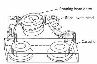
FIG. 46. Helical scan transport layout.
Rotating head drum Read - write head Cassette
----------------
5.3 Rotary Digital Audio Tape
The R-DAT format shares technology with the 8 mm camcorder VCRs. By optimizing a miniaturized helical scan system using 4 mm tape for direct digital recording of stereo audio, a very compact digital recorder, Fig. 47, has been made possible. New heads and metal particle tapes have been utilized to produce a long-playing cassette tape system with quality equal to the compact digital disk.
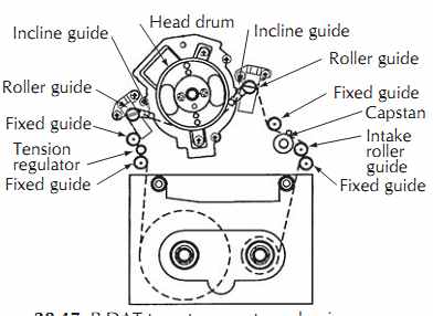
FIG. 47. R-DAT tape transport mechanism.
Capstan Intake roller guide Head drum Incline guide Tension regulator Roller guide Fixed guide Fixed guide Roller guide Fixed guide Fixed guide Incline guide
----------------------
The R-DAT format operates at two tape speeds, 8.15 mm/s (0.32 in/s) for recording and 12.23 mm/s (0.48 in/s) for widetrack playback of prerecorded tapes.
In spite of the very slow tape speed, very high data rates are made possible with a rotating head drum speed of 2000 rev/min and flying head velocity of 3 m/s. The resulting slant tracks are 23.5 mm (0.93 in) long and inclined at an angle of approximately 6.5( from horizontal.
The data is digitized to 16 bit resolution and recorded with double-encoded Reed-Solomon error correcting coding with interleaving between not only channels 1 and 2 but also adjacent scans of the flying heads, Figs 28-48. A 60 m (65.6 ft) tape holds 2200 Mbytes of information capable of encoding 2 hours of stereo music. Search for a desired program can be conducted at 60 times normal speed; rewind and fast forward without search is up to 180 times normal speed, allowing full rewinding in approximately 40 s.
The digital storage capacity of the audio R-DAT format has been greatly enhanced by newer technology to serve as a backup medium for computer hard disks.
The fourth generation of the Digital Data Storage format (DDS4) jointly developed by Sony and Hewlett-Packard from the original R-DAT format boasts a capacity of 20 Gbytes per 150 meter tape. The drum spins at 11,480 rev/min to achieve a data throughput of 2.87 MB/s before data compression and up to 7.62 MB/s after compression.
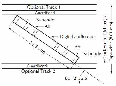
FIG. 48. R-DAT tape format
23.5 mm 60 o2' 52.5" Optional Track 1 Guardband
Guardband Optional Track 2 Subcode Aft Digital audio data Aft Subcode Track width (2.61 mm) Tape width (8.81 mm)
---------
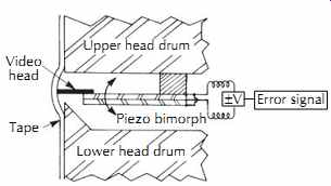
FIG. 49. A dynamic head positioner using a bimorph.
Video head Upper head drum Piezo bimorph Lower head drum Tape Error signal pV
--------
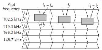
FIG. 50. Pilot signal tracking servo showing pilot frequencies.
5.4 Packing Density Maximization with Rotary Head Recorders
The professional analog multitrack formats are very inefficient in the use of recording tape. Nearly half of the tape width is devoted to guardbands between tracks.
These guardbands are required to minimize crosstalk between channels due to fringing and crosstalk within the heads. These problems are overcome in rotary head recorders that do not require guardbands.
Several aspects of the rotary head system contribute to the elimination of guardbands, including servo positioning of the tape, azimuth shifting on alternate scans, and the elimination of low-frequency components in the recorded signal.
The servo positioning of the helical scan tape during playback is analogous to a conventional longitudinal recorder with self-aligning guides to correct for any guiding errors. Control signals recorded along the edge of the tape are used to synchronize the motion of the tape past the rotating drum to the spinning of the drum.
This synchronization adjusts the position of the recorded tracks on the tape to exactly coincide with the path of the flying head. The active servo control of the tape motion duplicates any disturbances that may have occurred during recording to maintain correlation between the flying head path and the track, permitting tracks to be recorded abutting each other.
This technique can be carried one step further if the spinning head is augmented with a rapidly responding positioning actuator. FIG. 49 shows a scanning head mounted on a piezoelectric positioner called a bimorph.
If a voltage is applied to the bimorph, the head mount deflects and moves the head.
Since the bimorph can respond much faster than the servo system, tracking errors can be continuously corrected throughout the helical scan of the tape. This wider bandwidth, however, requires a method of actually sensing any errors when the head begins to slip off the center of the slant track. One of several techniques for this purpose is utilized in the 8 mm helical format.
As shown in FIG. 50, low-frequency tracking signals are added to the high-frequency data. Four different frequencies are recorded on four sequential passes, with the frequencies chosen so that the difference between adjacent frequencies is either 16.5 kHz or 46.2 kHz.
If the video head on track f1 plays back the signal accurately, only the signal f1 (102.5 kHz) is reproduced.
If the video head deviates toward the f4 track, it will pick up both signals f1 and f4 (148.7 kHz). The difference between these two signals, f4 - f1, will give an error signal 'f of 46.2 kHz, causing the video head to be moved back toward the f1 track immediately. If the video head shifts to the f2 track, another error signal f2 - f1 of 16.5 kHz will be produced, and the video head will be moved back toward the proper f1 track. Thus, the video head can be made to accurately follow a previously recorded track.
The close packing of adjacent tracks would cause serious fringing problems if the data signals on the tracks contained any long-wavelength information. To avoid any such problems, the audio signal is encoded using either digital or FM techniques to shift the frequency content upward and eliminate all low frequencies.
Isolation of the short-wavelength encoded signals between adjacent odd and even tracks is further improved by offsetting the azimuth tilt of the heads during recording and playback as shown in FIG. 51.
The resulting azimuth error for any signal leaking from the adjacent tracks will partially attenuate any crosstalk.
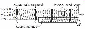
FIG. 51. Differential azimuth recording technique.
A helical scan recorder must have additional circuitry to assemble the digital data from several tracks into a serial stream that is recorded as blocks of data by the scanning head. The data must usually be replaced as an entire block, necessitating a complete rewrite of all channels if any channel is changing.
All of the digital circuitry of a helical recorder can be squeezed into just a few custom integrated circuits.
The newer generations of ADAT machines, for example, adopted digital servos for controlling the transport so that all of the motor servos could be consolidated into a single chip, eliminating the need for any analog servo adjustment potentiometers. The digital signal chain is also highly integrated, resulting in an amazingly uncomplicated main circuit board with just a few ICs for the entire machine.
5.5 Heads for Digital Tape Recorders and Hard Disk Drives
The packing density of the data on hard disks in 1990 was around 100 mb/in^2. At the time of this publication, it is over 200 Gbits/in^2.
FIG. 52 shows a thin film digital tape head.
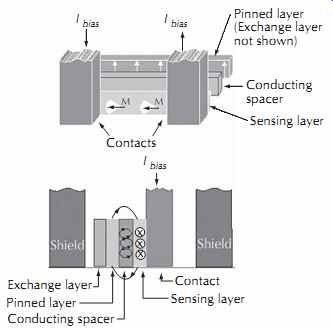
FIG. 53. Giant magnetoresistive head.
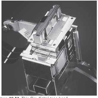
FIG. 52. Thin film digital tape head.
As the areal density of the data on tapes and disks increases, each bit must shrink in size. The smaller bits contain less magnetic energy and generate smaller electrical pulses in the coil of a read head. The resulting loss in SNR eventually imposes a useful lower limit on the size of the bits.
This limit has been pushed back by read head technology called giant magnetoresistive (GMR) or spin valve heads. (The term giant differentiates these very high-output heads with giant output signals from earlier low-output magnetoresistive heads.) The GMR head is fabricated by vacuum deposition, creating a sandwich of metals that changes resistance when excited by a magnetic field. The rear layer of the sandwich shown in FIG. 53 has a fixed or pinned magnetic field that serves as a reference. The filler of the sandwich is a magnetoresistive (MR) material chosen for a large change in resistance per change in magnetic flux. The front outer layer is a magnetic probe that actually samples the magnetic flux of the bits on the disk. As the magnetic polarity of the data bits reverses, the angle of the magnetic field in the outer layer spins back and forth. Part of this field bridges through the center layer to the pinned rear layer, causing the resistance of the MR layer to change. The resulting output signal has a much better SNR than an equivalent read head.
Since the GMR effect does not work in reverse to generate a varying magnetic field when driven by an electrical signal, we still need a coiled conductor for writing the data onto the disk. The solution is a composite head that has both a GMR read element and a coil for writing. The entire head, including the GMR read element and the coil for writing, can be fabricated together using thin film techniques. A single thin film wafer may contain up to 20,000 heads.
Most digital recording schemes drive the record head hard enough to saturate the medium in one polarity or the other. If the head is tracking exactly over any prior data, the old data will be completely overwritten. Unfortunately, the tolerances of the head tracking system may cause slight alignment errors that leave a bit of the old signal unerased.
One method to remove the residue is to use a straddle erase technique that resembles the outriggers on a Hawaiian canoe. Two thin erase cores straddle the desired track and trim off any of the prior signal that wasn't covered by the new recording.
A newer technique is to write wide and read narrow.
Just as we discussed for analog recording, we can write a track that is wider than the read core. The extra width of the recorded track allows for a small tracking error.
This technique is easily implemented with GMR heads since these heads have separate read and write elements.
The read element is fabricated slightly narrower than the write element to create the desired overlap.
5.6 Magnetic Disks
A 2500 foot roll of 2 inch recording tape has enough surface to carpet a large living room. A 60 minute DTRS tape would only cover half of a couch. In comparison, a multigigabyte hard disk in a digital audio workstation uses a few 3½ inch (89 mm) diameter magnetic disks with a working area about the size of your footprint. Although the basic technology of all of these products is similar, the precision required in their manufacturing increases rapidly as the size shrinks and the density increases.
5.6.1 Floppy Disks
Floppy disks were close cousins to magnetic tape.
Although the disks were cut from large rolls much like the jumbo rolls from which magnetic tape is slit, the coatings parameters were very different.
The diskette, which we now call the floppy disk, was developed around 1970 as a read-only device. The contents of the prerecorded diskette were loaded into a computer or storage system to furnish startup or diagnostic information, much like a boot ROM in today's computers. Over the next ten years the product evolved from an 8 inch diameter single-sided read-only device to a 3.5 inch double-sided read/write device with twenty times the capacity of the original diskette.
Although the original diskette operated on only one side of the disk, the media had magnetic coatings on both sides to promote flatness. The symmetric construction of the disk was eventually exploited to double the data capacity by recording on both sides.
By the end of their evolution, floppy disks utilized a very thin coating of cobalt doped gamma ferric oxide.
The coating thickness was about one-fifth the thickness found on our analog mastering tapes, and the particle coercivity was about twice as high.
One important difference in floppy disk media is that the magnetic particles for a spinning disk must not be oriented in a single direction as on our audio tapes.
Recording characteristics degrade several dB when an oriented tape is operated crosswise to the intended direction. A linearly oriented disk would therefore see large peaks and troughs in output at twice the rotational speed. To avoid these fluctuations, the floppy disk coating process is optimized to either disperse the magnetic particles in a random orientation or orient the particles circularly.
The floppy disk operated with the magnetic head in direct contact with the magnetic media, just as in a tape recorder. As a result, the floppy disk system was subject to head wear and head clogging due to dirt and debris.
5.6.2 Rigid Disks
Tape and floppy disk recorders utilized contact recording with the head touching the recording medium.
This continuous sliding contact produced wear that limited the life of the heads and medium. The flying head of a hard disk drive eliminates this contact, greatly extending the life of the head and disk.
High digital densities require very low flying heights on the order of 0.4 µinch (10 nm) to avoid excessive spacing loss. Any surface irregularity that sticks up more than the flying height will impact the flying head.
To make matters worse, even smaller defects can upset the aerodynamic flow of the air around the head enough to cause instabilities that can make the head crash into the disk surface. To avoid these problems, the disk substrate and the magnetic coating must both be extremely smooth.
Aluminum/magnesium alloys and glass are the preferred substrate materials, with glass rapidly gaining popularity as disk sizes decrease. Plastic disks, some with servo patterns pressed into the surface during the molding process, are also entering the market.
Aluminum disk substrates are cut from special aluminum sheet that is optimized for flatness and surface smoothness. The disks are polished and then plated with an undercoat of nickel phosphorus (NiP).
Glass and glass/ceramic substrates are rapidly displacing aluminum disks. Glass offers a very smooth surface and a higher stiffness than aluminum. The benefits are a lower flying height with fewer surface defects and a disk that is more robust.
The aluminum or glass disk is coated with multiple layers that include foundation layers, the active magnetic surface and protective overcoats. Although earlier disks were spin coated with a slurry resembling the coating for magnetic tape, modern disks are prepared by plating and ion bombardment. Hard diamond-like overcoats and surface lubricants protect the magnetic layer from accidental contact with the head.
-------------
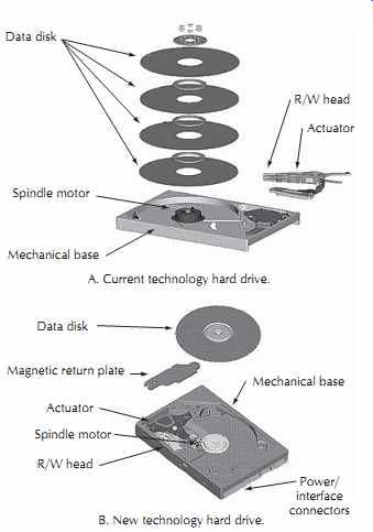
FIG. 54. Interior of a hard disk drive.
R/W head Actuator Spindle motor Mechanical base Data disk Data disk Spindle motor R/W head Mechanical base Magnetic return plate Actuator Power/ interface connectors A. Current technology hard drive.
B. New technology hard drive.
----------------
5.7 Hard Disk Drives
Rotating disk drives offer very rapid random access to a huge array of data, FIG. 54. This yields two very important benefits. First, the rewind, fast forward, and auto-locate functions of a tape recorder become nearly instantaneous. This speeds up operation, especially during editing sessions.
A second and much more important benefit is the ability to rearrange the output data. Assuming a fast host computer with versatile digital audio workstation (DAW) software, the user can construct a song from a multitude of track segments almost as if he or she cut each track of a reel of multitrack tape into a thin ribbon and then chopped and spliced the individual ribbons back together to arrange the song. This incredible versatility has fueled the rapid replacement of analog audio tape recorders in recording studios. Even when an analog recorder is employed for the initial capture of the music, the analog tracks will probably be digitized and loaded into a DAW for editing and mixing.
To demonstrate how data are stored on a spinning disk, consider the inner workings of a representative single-platter drive. Although this unit is only a single-platter, 15 Gb entry-level drive under $100, this drive's areal density of 22.5 Gb/in^2 led the industry when the drive was introduced in early 2001. We will look at the major subsystems to rotate the disk, position the read/write/erase head assembly, and process the data to and from the disk.
The spinning disk is an aluminum or glass disk covered with a magnetic layer. Since smaller disks are flatter and more rigid, the trend has been downward in disk size from 14 inch diameter disks in 1960 to disks ranging from 3.5 inch down to 1.8 inch diameter today.
Smaller disks can spin faster and rotation rates have risen from about 3000 rpm for the 14 inch disks to targeted speeds of 22,000 rpm for high-performance small disks.
These higher rates and tighter tolerances are exceeding the capabilities of the ball bearings that support the spinning disk, requiring new types of bearings. Fluid dynamic bearings replace the rolling balls in a ball bearing with a film of oil that is less than one-tenth the thickness of a human hair. In addition to providing tighter tolerance, the fluid dynamic bearing is quieter, longer lasting, and more rugged.
The spindle assembly includes an integral motor for spinning the disk. The power required from the spindle motor due to aerodynamic drag of the spinning disks is
Pn Z2.8 u r 4.6
uv
(eqn. 11)
where,
n is the number of platters, Z is the angular velocity of rotation, r is the disk radius.
Additional power is required to overcome the friction and viscous losses of the bearings.
The magnetic data on the disk is accessed by magnetic heads flying over the surface of the disk. The very close spacing between the head and disk is maintained by a cushion of air generated by the aerodynamic design of the head. For our example drive, the head-to-disk spacing is 0.6 µin (15 nm) or the wave length of orange light.
Since the head cannot fly when the disk rotation stops, provisions must be included to transition from flying to non-flying status. Some drives land the heads on a dedicated portion of the disk periphery appropriately known as the landing zone. Other drives move the head to an extreme position to engage a parking ramp that holds the head away from the disk. The parking ramp also provides protection from shock and vibration incurred during shipping or handling of the computer.
Some of today's disk surfaces are so smooth that the head will literally stick to the surface after landing. To overcome this stiction, the surface of the disk may be textured with microscopic bumps. The bumps may require an increase in the flying height, thereby reducing the maximum storage density of the disk.
To avoid these problems, the example drive uses a parking ramp at the center of the disk. The resulting ability to use an untextured disk surface is a major reason for this drive's very high packing density.
The flying head is mounted on metallic spring matrix called a gimbal that allows the head to assume the proper flying attitude parallel to the disk surface. The gimbal is at the end of a long support arm called a flexure that cantilevers the head above the disk surface.
The flexure lightly presses the head onto the disk surface to overcome the aerodynamic lift generated by the head.
The flexure is attached to an actuator that moves the head to the appropriate track of magnetic data on the disk surface using either linear or rotary motion. The linear actuator is very similar to the voice coil and magnet of a loudspeaker. A current in the coil produces a magnetic field that interacts with the field of the permanent magnet to create a linear force along the axis of the coil. A sled assembly with ball bearing wheels maintains alignment of the coil as the head moves in a straight line along a radius of the disk.
A rotary actuator is a pivoting device that moves the head in an arc across the surface of the disk. The arc causes the head to depart from absolute tangency to the disk, but the error is relatively small since only 30% of the disk's radius contains data. The actuating force is once again generated by a coil and magnet, but in this case the components are curved to match the pivoting motion. The support bearings and structure of the rotary actuator are simpler and less expensive than the linear actuator's sled.
The actuators are part of a closed loop control system that moves the head to the appropriate radius on the disk. The desired address comes from a translator that converts a data address into a physical radius. The feedback to the control system is the actual data that is being read from the disk. Older systems used one surface of one disk in the stack of disks for nothing but positioning information. These dedicated servo drives contained prerecorded positioning information defining the radius and the angle of rotation. The actuator would move to match the desired radius to the data being read from the servo platter.
Newer drives save the expense of a servo platter by using information written on the normal data surfaces.
These embedded servo schemes have short blocks of address information scattered around each circular track at regular intervals. These systems can also sense changes in the readout pattern when the head begins to move off the centerline of the data track.
Embedded servos have allowed designers to greatly increase the track density on the surface of the disk.
Any small changes due to temperature and wear are actively sensed at the exact point where the data is being written and read, not at a remote location on another disk. Our example drive uses an embedded servo to pack 40,000 tracks per inch of radius.
The current trend is to utilize digital signal processor (DSP) chips for the tracking servo and spindle motor control. Other electronics tasks include a buffered digital data interface with the host computer, error detection and correction and encode/decode of the data to optimize the read/write process.
All of the mechanisms and servos in a disk drive would be useless if any dirt gets into the system. When a head is flying at a spacing of less than 1 µinch, even a particle of cigarette smoke can cause a catastrophic collision that might destroy the head and/or disk. To avoid contamination problems, the entire head and disk assembly are enclosed in a clean environment. Any air entering the sealed head/disk assembly for cooling or atmospheric pressure balancing passes through a filter that traps all dirt.
5.8 Hard Disk Electronics
The hard disk drive also features very dense circuit packaging. A typical drive has less than 20 in2 of circuit board with just a few highly integrated chips. The block diagram of FIG. 55 shows the basic functions that are squeezed into this small space.
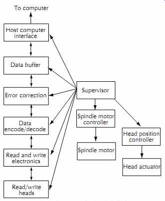
---- FIG. 55. Block diagram of a hard disk drive.
Host computer interface To computer Data buffer Error correction Data encode/decode Read and write electronics Read/write heads Supervisor Spindle motor controller Spindle motor Head position controller Head actuator
---------------
The spindle motor controller provides the servo loop that turns the disk at a constant speed. The controller also provides the acceleration and deceleration profiles during startup and shutdown.
The actuator servo controls the linear or rotary voice coil motor that positions the head actuator at the proper radius of the disk. This servo must provide rapid seeks to the desired data and track any eccentricities or other disturbances that might cause a tracking error. The current trend is to program custom DSP chips to serve as digital servos for both the actuator servo and spindle motor controllers.
The data path circuitry provides many of the interleaving, error correction, and modulation code functions described in conjunction with the digital tape recorder above. In addition, the interface provides data format- ting and buffering to handshake with the host computer system.
The hard disk data path is much faster than the DASH tape recorder. Read/write circuits for hard drives are pushing frequencies of a gigahertz, yielding data rates of 100 megabytes/s. At 3 bytes per 24-bit audio word and a sample rate of 96 k-samples/s, this represents about 250 audio channels. This number is best case, and the throughput drops drastically if the drive must read and write simultaneously while seeking various tracks of data.
The trend is toward higher levels of integration in disk drives, with more of the very high-speed circuitry moving closer to the read/write head to avoid delays and waveform distortions due to wire lengths and inductances. (Electricity travels about 1 foot in a nanosecond, and 1 ns is the period of one cycle of a gigahertz signal.) The adoption of fluid dynamic bearings permits higher disk rotation speeds that reduce the latency time for a desired block of data to rotate to the head's location. The average latency is half the rotation period for the disk. For a 15,000 rev/min (250 rev/s) disk drive, the average latency is 2 ms.
5.9 Formatting Media
Digital media typically require one or two stages of preparatory recordings of control information before user data can be recorded. Low-level formatting involves basic housekeeping tasks that allow the drive to properly and accurately move the media and heads to the correct physical locations. In addition, high-level formatting defines the nature of the digital data blocks regarding sector and block lengths. Formatting also checks for media defects, marking bad sectors and relocating data to good sectors.
Formatting may also include writing control tracks with synchronization and address information. To illustrate why, consider a helical scan digital audio tape recorder. We can start with a blank tape and begin a recording. The machine records the helical stripes of data with embedded address information and a control track along the edge of the tape to facilitate synchronizing the linear tape speed with the rotations of the helical drum during subsequent playbacks. If we stop the recording, we also stop the recording of all of the address and synchronizing data.
If we wish to restart the recording by punching in at our previous exit point, we must seamlessly append address and synchronization data to the ends of the previously recorded tracks. But what happens if the recorder is running at a slightly different speed, perhaps due to the recorder warming up, when we punch in? Whenever we play back the tape, the recorder must abruptly change the tape speed at the punch-in point.
A better technique is to prerecord or format the entire tape with address and synchronizing information.
This will allow us to locate any address on the tape in a continuous manner, and the tape speed will be constant throughout the tape.
Formatting a tape or disk can be a very time consuming task. Tapes typically must run through the machine at normal speed; hence a 30 minute tape would require 30 minutes for formatting. Preformatted tapes with prerecorded address and synchronization tracks are now available from the tape manufacturers for some of the digital audio formats. In addition to saving time, the preformatted tapes also reduce wear on the recorder.
Hard disk formatting may vary from minutes to many hours, depending on the operation. The lengthiest operation is repacking all of the data on a disk. After a file has been changed a number of times, the physical file may be many sections scattered widely across the surfaces of the disks, leaving unusable islands of updated and deleted data. The repacking operation relocates and reassembles the files as contiguous data, freeing up the wasted space. Repacking also checks the disk surface for defects. If a sector is contaminated with errors, the drive may try several read operations to recover the data. Some drives will also move the head off-track slightly to recover poorly written tracks. Bad sectors are marked so that they will not be reused.
Although audio tape recordings do not contain any addressing and synchronizing information embedded within the audio recording, some applications require adding a track of SMPTE/EBU timecode for synchronization or editing. For live production work, the time code track will be recorded on all of the audio and video machines to allow later synchronization of multiple machines.
Timecode is also used during the editing process to identify segments that are to be assembled onto a master reel. Timecode is first prerecorded or striped onto the master reel to allow the editing computer to precisely locate the destination addresses of all of the edits. The computer then locates the appropriate segments in the time-codes on the source reels and copies the audio and/or video onto the designated timecode section of the master reel.
5.10 Long-Term Storage
A common question is "How do I store my digital data when I finish a project?" Many users have decided that hard disk drives are cheap enough to just store the hard drive as the archival copy. This strategy is fraught with problems that could come back to bite the user. Disk drives have several failure mechanisms that can render the data unrecoverable over time.
Some systems park the head on the surface of the disk. Over time, the lubricant that is embedded in the disk's coating can migrate to the surface and "glue" the head to the disk. This problem is avoided with drives that have parking ramps to hold the heads off the surface of the disk when the disk drive isn't running.
Another problem is the spindle bearings. If the drive is stored for extended periods, the lubricant may degrade or migrate away from the critical bearing surfaces. This can lead to bearing failure when the drive is restarted.
The manufacturer rates a typical drive for about three years of useful life. There is no separate specification regarding storage life. Expecting a long storage life is an act of sheer faith.
The advantage of a tape or optical disk backup of the digital data is that the media and the mechanism are two separate items. The drive mechanism can be maintained and serviced without involving the media. The problem then becomes finding a working sample of the appropriate drive, or finding parts and a trained technician to fix a nonworking sample. Several digital tape formats have already reached the point at which finding a working tape deck to play the tapes is difficult or impossible. This problem will only get worse in the future.
If the data is valuable, the user should map out a backup strategy that will assure accessibility. This may require occasional copying of the digital information to newer formats. If nothing else, the user should have a schedule to verify every year or two that the original data can still be accessed without any degradation.
5.11 Data Interchange
Standards for compatibility of digitally recorded tapes have become much more difficult to achieve because of the wide range of choices open to the digital audio designer. The common problems of mechanical compatibility of tape speed and track format are still present, plus the sampling rate, data format, timing, and error-handling methods must also be compatible.
The rapid evolution of digital audio technology in these areas, which has already rendered several generations of digital audio recorders obsolete, has blunted any attempts at standardization at the media level. The point of data compatibility has moved up to the electronic interface between systems. At this level we find widely used standard protocols such as AES/EBU, SPDIF, and ADAT light pipe. Additional work, such as AES 31, to standardize file transfer protocols between hard disk systems will provide for the electronic trans port of audio files throughout a facility via local area networks, and throughout the world via the Internet.