AMAZON multi-meters discounts AMAZON oscilloscope discounts
There is an old proverb: "If you want a rabbit stew, first catch your rabbit." An electronic technician would say: "If you want to analyze a circuit waveform, first display your waveform." Displaying waveforms is something like catching rabbits.
A waveform can be an elusive will-o'-the-wisp. For example, suppose you connect a scope at the plate of the second IF amplifier in a TV receiver and nothing happens. There is a reason for the missing waveform, of course. First, there may be no signal present (a circuit defect might be stopping the signal) . Second, a technical error could have been made, such as using a low-capacitance probe instead of a demodulator probe. Third, the scope controls could be adjusted incorrectly-perhaps the vertical step attenuator is set to the low end of its range.
Fourth, circuit loading might have thrown the stage under test into oscillation.
When this type of difficulty occurs, carefully check each of the following possibilities:
1. Is a waveform present at a previous test point in the circuit? If so, it is a good possibility that nothing happens at the following test point because the circuit is defective between the two points.
2. Is there conclusive evidence that a signal is actually present-such as some semblance of an image on the picture tube screen? If so, look to see whether a suitable probe is being used; as noted previously, a modulated-IF signal can be displayed only with the aid of a demodulator probe.
3. Are the scope and probe in working condition? If the scope is operating, you will see a distorted 60-cycle sine wave when you touch your finger to the scope vertical input terminal. If the demodulator probe is working, you will see a sine-wave pattern when the modulated output from an AM generator is fed via the probe to the scope.
4. Is the probe properly connected to the scope? Everyone at some time has reversed cable terminals by connecting the ground lug to the "hot" input terminal. Occasionally, a whisker from a frayed cable will short out the input terminals. In other words, look for obvious defects first, before condemning the equipment.
5. Is circuit loading causing the IF stage to "take off" and oscillate uncontrollably? This happens in a certain percentage of tests. In such a case, the dead stage comes to life when the probe is moved from a plate terminal to a grid terminal, or vice versa.
UNEXPLAINED HUM INTERFERENCE
All experienced technicians have run into hum interference that did not make sense. An example is illustrated in Fig. 1-1.
In other words, circuit operation is such that high-level hum cannot be present, but for some unexplained reason a high-level hum interference appears to be present at every test point in the circuit. When this puzzler confronts you, immediately check the ground return to the scope. If you are using a coax input cable, there is a high probability that an ohmmeter check will show an open ground circuit. Or, if you are using open test leads, look to see whether the ground lead is clipped to a point on the chassis that is actually grounded. Support brackets, for example, might look like a ground connection and in fact be floating.
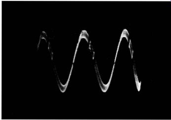
Fig. 1-1. Small signal, large hum.
PULSATING PATTERN
A curious and sometimes baffling situation occurs when the scope is operated at maximum sensitivity. A pattern is displayed normally, except that the waveform flips up and down on the screen. Usually the flipping occurs at a fairly slow rate, although it may be fast enough to make the waveform appear blurred. In this case the test setup is "motorboating." There is feedback present between the power supplies of the scope and the unit under test.
In some cases, the test setup can be stabilized by turning over the power plug of the scope. However, in stubborn situations both the scope case and the chassis under test must be physically grounded. Beware of hot-chassis equipment in all cases use a line-isolating transformer to power a hot-chassis device.
Otherwise, a premature Fourth-of-July pyrotechnics display can be expected-not to mention the possibility of serious shock to the operator.
SCOPE OSCILLATES
Sooner or later, a scope operator will run into another type of puzzler caused by a scope oscillating uncontrollably. For example, you might connect a sound-IF coil across the scope vertical input terminals and be confronted by an off-screen, high-frequency pattern. This self-oscillation is more likely to occur when a preamplifier is used with a scope, but it occasionally happens when a coil is connected directly to the scope vertical input terminals. It occurs when the plate circuit of the input stage is not sufficiently isolated from the grid circuit, and a tuned-plate-tuned-grid oscillator system is established. In other words, the coil under test is operating like a grid tank, and feed-back due to interelectrode capacitance sets up self-oscillation with the plate-circuit peaking coil (s) and stray capacitances serving as a plate tank. This difficulty is most commonly encountered with preamps that do not employ a cathode-follower input stage. If it does occur, the preamp cannot be used in the particular test. A completely useful preamp must have a cathode-follower input-otherwise, it is quite likely that tests of high-Q coils in certain resonant-frequency ranges will become impossible because of self-oscillation.
HOOKED BASE LINE
Another baffling situation sometimes met in high-impedance circuit tests is a bending or hooking of the base line, usually toward the left end. In other words, a normal horizontal base line is present as long as the circuit under test has low or moderate impedance, but when you test across a high-impedance circuit the base line dips down or curves upward at the left end (Fig. 1-2) . The amount of base-line distortion changes with the setting of the vertical-gain control. Distortion is increased when the impedance across the scope vertical input terminals is increased.
This difficulty is caused by the presence of sawtooth-deflection voltage in the vertical-input system of the scope. It sometimes develops when the front panel does not make good connection with the case. It may be caused by leaving a "floating" lead from the pulse-gate terminal near the scope vertical input terminals. In rare cases the internal shielding of the scope is insufficient to prevent the pick up of stray fields from the deflection system by the step-attenuator section.
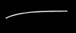
Fig. 1-2. Hooked base line.
SPURIOUS PI P ON SINE-WAVE DEFLECTION
An analogous type of distortion is sometimes observed when a scope is operated on 60-cycle sine-wave deflection, as when displaying a frequency-response curve. If you see a spurious pip on the curve or base line, it might be caused by crosstalk from the sawtooth oscillator into the vertical amplifier of the scope. Try changing the setting of the sawtooth-frequency control to see if the pip starts moving or changes its rate of movement on the pattern. If it does, the cause is clear. Scopes which have this inherent characteristic are provided with an off position for the sawtooth-frequency control-the off position must be used in such cases.
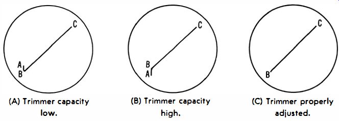
Fig. 1-3. Trimmer adj. patterns. (A) Trimmer capacity low. (B) Trimmer capacity
high. (C) Trimmer properly adjusted.
WAVEFORM CHANGES WITH STEP-ATTENUATOR SETTING
Modern scopes have frequency-compensated vertical-step attenuators. That is, the attenuator resistors are shunted by trimmer capacitors that must be adjusted to eliminate frequency discrimination. If you switch to an adjacent step and find a change in waveshape, the cause is most likely incorrect trimmer adjustment. Usually, you will find that the associated resistor has been damaged by overload and increased in value. Hence, the resistor should be checked before the trimmer is readjusted; otherwise, you are likely to end up with an incorrect attenuation factor on the particular step.
Overload and resistor damage commonly result from applying excessive voltage to the scope vertical input terminal. Ill-advised tests in horizontal and vertical sweep circuits are generally responsible. In such cases the blocking capacitor of an AC scope will probably be punctured and require replacement. After defective components are replaced, it is quite easy to adjust attenuator trimmers correctly without the use of special equipment. Simply connect a test lead from some point in the horizontal-deflection system to the scope vertical input terminal. Adjust the sawtooth oscillator to a rate of approximately 20 khz. Then, adjust the pertinent trimmer for a straight diagonal line on the screen (Fig. 1-3).
LOW-CAPACITANCE PROBE DISTORTS WAVEFORM
You may find that the step attenuator is properly compensated in the previous test but that distortion appears when the sawtooth test voltage is fed into the scope via the low-capacitance probe. This indicates that the probe is out of adjustment.
A low-C probe contains resistance and shunt capacitance in the same configuration as the step attenuator itself. Hence, if the shunt capacitance has an incorrect value, the probe will distort complex waveforms. Some probes have an adjustable trimmer capacitor-in this type set the trimmer in the same manner as previously described for a step attenuator.
If your probe has a fixed compensating capacitor, it will be necessary to replace the capacitor with another having correct value. This necessity generally arises when a general-purpose low-C probe is used with a scope to which it is not matched. However, the same problem occurs when the coax input cable of a low-C probe is replaced with a cable having a different capacitance. In any case, a low-C probe does not serve its purpose unless the time constants of both probe and scope-input system are equalized.
In a few cases you will find that a scope has considerably different input capacitance and resistance values on various steps of the vertical attenuator. Such scopes cannot be used satisfactorily with low-capacitance probes. When circuit loading is a problem due to capacitive loading by a coax input cable, the best that can be done is to use open test leads. However, open leads often cause difficulty due to stray-field pickup when high-impedance circuits are under test. Hence, professional test procedures in TV circuitry require the use of a scope which has reasonably constant input resistance and capacitance, plus a matching low-C probe.
PROBE WEAKENS SIGNAL EXCESSIVELY
Various scopes have different vertical-sensitivity ratings. When testing in low-level circuits with a low-C probe, it is desirable to have high vertical sensitivity available, or the incidental attenuation of the probe may make the pattern height inadequate. If you do not wish to replace the scope with an expensive model having considerably higher sensitivity, you may choose to use a wide-band preamp. Another possibility is to employ a simple cathode-follower probe instead of a low-capacitance probe. A few scopes provide a choice of both low-C and cathode-follower probes. For purposes of comparison, a typical cathode-follower probe causes a 20% voltage loss, while a low-C probe causes a 90% voltage loss. The cathode-follower probe also imposes less circuit loading than the low-C probe.
A low-C probe is not only less expensive, but it is also easier to adapt to ordinary scopes, because a low-C probe does not require supply voltages. Scopes designed for use with cathode-follower probes have special vertical input connectors which provide heater and plate-supply voltages to the tube in the housing of a cathode-follower probe. While you can modify any scope to accommodate a cathode-follower probe, it is not an easy job.
GETTING ACQUAINTED WITH WAVEFORMS
Beginners are well advised to make haste slowly when starting waveform analysis. It is possible to become discouraged at the outset by neglecting basic principles of scope operation. If tests are made first with an ordinary 60-cycle sine-wave input, it will not take long to "get the feel" of the scope controls. Note carefully what happens as you change each control setting.
When something unexpected occurs, stop right there and ask why. For example, if you have the vertical step attenuator "wide open" and attempt to adjust pattern height by means of the continuous attenuator, the waveform may appear neatly clipped. This happens because the input cathode follower is overloaded. Hence, reduce the step-attenuator setting so that the continuous (vernier) control does not need to be set near zero.
Suppose an odd pattern which does not respond to a change in the sawtooth-oscillator control setting is displayed. Remember that the function switch must be set to the sawtooth position to obtain a conventional sine-wave display. Furthermore, the sawtooth function may not be identified as such on your particular scope--it might be called "Int Sync," "+ Sync," or possibly some other designation. In any case, the instruction book for the scope will explain the designation.
After you gain confidence in displaying 60-cycle waveforms, it is advisable to gain experience with sine waves of other frequencies from an audio oscillator. Then, square waves or pulses can be investigated. These are all simple waveforms that are not mixtures. When you "graduate" to video signals, you will find that two basic patterns are obtainable, depending on the sawtooth-frequency setting. The vertical-sync interval is visible on 30-cycle deflection, while the horizontal-sync interval is visible on 7,875-cycle deflection.
Many operators who are "at home" with waveforms displayed on sawtooth deflection feel baffled when tackling frequency-response curves displayed on 60-cycle sine-wave deflection. The latter is a more difficult situation, because horizontal deflection voltage must be properly phased. Moreover, the visible retrace must be blanked by appropriate controls.
Again, the secret of success is to make haste slowly and be sure that you understand each step and the reason for it.