AMAZON multi-meters discounts AMAZON oscilloscope discounts
This last section will be a series of small paragraphs, each presenting an idea dealing with the design or concept of building a robot. Some are cheaper ways of doing things we have already discussed, others bring up factors that need to be considered in a society populated with robots. The first story will give you the flavor of the section.
LAWS In Japan, an attempt to bomb the home of a syndicate leader with a radio controlled helicopter, toy variety, was foiled by the police. We may have to have some controlling laws governing the functions and operations of hobby robots as they increase in capability.
TYPES OF HOBBY ROBOTS
In the general case a robot is constructed to prove that one has the intelligence and mechanical-electronic electrical-physical capability to make a machine that resembles in some way, a person, or the actions of a human. Thus, if nothing else, the construction of a robot of the hobby variety is a challenge, and makes one investigate most of the fields of science and engineering before the task is accomplished. We might say, then, that we build hobby robots to learn, and to fascinate ourselves and our friends.
Many persons and companies as well as scientific institutions are making, or developing kits for, or are investigating the use of, hobby type robots. This type robot is distinguished from its industrial brothers in that the industrial robot has a definite task to perform, or many of them, and it does this well and for long periods of time. Tasks as demanding as making printed circuits and inserting parts on such circuit boards, something a human tires of very quickly, to the handling of thousands of pounds of equipment or materials in various plants. The hobby robot, on the other hand, is just for the pleasure or education, or satisfaction of the creator. Some types have been constructed just to investigate how far one can go in putting some kind of intelligence into a machine of some type. That, in turn, leads to much study and research.
But for the many units which simply run around, or draw lines on something under computerized command it seems the satisfaction is simply to have built such a machine. It is our belief that with technology at the current state of the art that it is, even hobby robots should do something useful.
One robot which has been built and named Midnight Special, uses various types of light sensors to get information about paths through mazes. The information he derives is sent to a computer where it is stored and analyzed. When the Midnight Special has made one trip through such a maze it then can repeat its path without any deviations or problems or trial and error efforts. This kind of operation is said to be one in which a robot has been given some kind of intelligence.
Certainly, it is a system in which the robot learns by its mistakes. Hobby robots should have this kind of capability.
WHO? The robot builder comes from a diversified segment of our population. From the college professor to the high school science major. We found it interesting that a former college Physics professor found pleasure constructing hobby type robots. He said that his interest is in constantly trying to make his robot do more things, and do them more intelligently. That brings to mind the giant robot of Benjamin Skora which is able (so they say) to vacuum the carpet, walk the dog, serve drinks to friends, and answer the door! There will be more and more hobby robot kits available as time passes. They will be able to do more and more things, and will give their constructors hours of fun and pleasure putting them together, and watching them work. Like the radio controlled model airplane activity, the stage of hobby robot development is rapidly passing from the "built it all, figure it out, put it together, make it work" stage into the level where anyone can simply buy a kit and have it do almost anything the human mind can conceive of it doing.
REMOTE CONTROL OF HOBBY-TYPE ROBOTS
We refer you to the sketch of Fig. 1. It will receive feedback signals of voice, TV, mechanical movements, heat, light, and so on from the robot via radio communication. The robot will get its instructions and voice generation commands from the home computer by a return radio link. It is not such a long way off. The technology for this kind of operation is available. Modern radio control transmitters already are able to handle streams of pulses with reliability, and they are small and compact and do not use much power. They could easily be incorporated into a robotic form, or used at a home base station. The output of the computing section would modulate the transmitter, and in the robot we would find the second half of our communications system which would take the commands, use the memorized software programs, and cause the robot to do whatever we have planned for it to do.
MAGNETIC CONTROL
To make such a robot function around the home, it might be possible to use magnetic induction loops in rooms, and the robot could have sensors which would be able to pick up the signals from the centrally located computer in the house and do the things the computer directs it to do. Essentially we are saying that hobby robots, as well as commercial, industrial robots do require computer direction as they do things better.
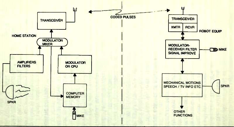
Fig. 1. A telemetry system for a robot's remote control.
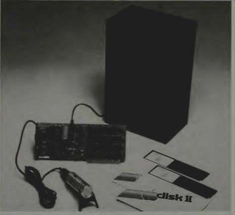
Fig. 2. The Mountain Hardware Supertalker system for the Apple computer
(courtesy Mountain Hardware).
THE MOUNTAIN HARDWARE SUPERTALKER: SD200
A talking circuit which was designed to be used with the Apple computing system is illustrated in Fig. 2. This system memorizes certain phrases and words and can use the memorized information to respond vocally to persons, under various conditions. This unit works with the Apple II Computer. It digitizes human speech and stores it, then it can play back this digitized speech through a speaker. The voice system consists of a card which plugs into a peripheral slot on the Apple II, and the mike, circuit board, and speaker shown.
There is an extensive software package which permits the user to interactively develop a phrase diskette which may contain many tables of phrases. Each table can contain several words, phrases or complete sentences, which the computer can select.
Here is how the system operates. The Supertalker board Fig. 2, has electronic circuits which convert the analog mike signals into a digital pattern which can be saved in memory units. The board's circuits accept these digital pat terns and transform them back into analog signals for use by a loud speaker.
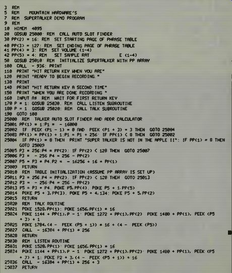

Fig. 3. One Supertalker demonstration program (courtesy Mountain Hardware).
The circuit board has an on-board ROM that is a 256 byte type. This ROM is accessible from BASIC by a call instruction to address CNO0 (Hex) where N equals the slot number that the board is in. Calling this address will place you in the talk mode, and a call to CNO3 (Hex) is for the listen mode.
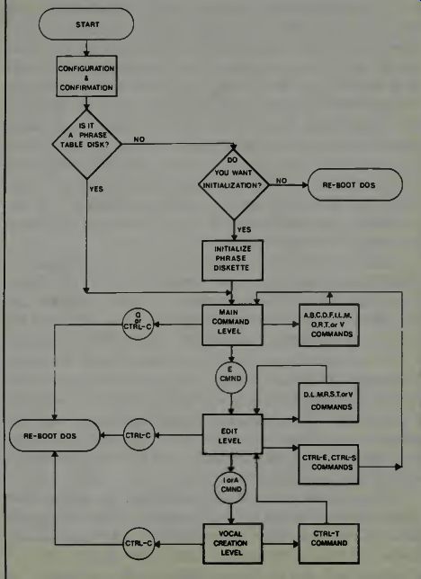
Fig. 4. The Supertalker computer flowchart (courtesy Mountain Hardware).
One Supertalker sample program is shown in Fig. 3, and the computer flowchart is illustrated in Fig. 4.
CHECKING ERRORS IN DATA TRANSMISSION AND SOME ROBOTIC-SYSTEM PROBLEMS
Among the professionals, there are several methods by which data information can be checked and the capability of a system to transmit the bits accurately and completely is determined. One of these methods is to use a parity bit for each word or character and inspect this. Parity is a system in which we add a pulse to a coded group in such a way that for even parity, the sum of all the l's will be an even number, and for odd parity, the sum of all l's will be an odd number. In the transmission of an even parity code, those bytes which have an even number of l's are not changed. In effect, a zero is added to the extreme left of the byte binary sequence. But, if the number of l's in the byte is odd, then a 1 is added to the left to make the numerical total of l's even. A byte with the wrong number of l's has an error in it.
Other writers, in discussing the checking of data in transmission systems have indicated that a cyclic redundancy check might be used. This means, essentially, that you re transmit the same information several times and if it all comes out the same, then the system has no errors-at least for that transmission period. Checks using special messages, such as the "Quick Brown Fox" which require transmission of characters representing all keyboard letters and numbers might be used. If, on the receiving end, one knows what the sequence of transmission is for this kind of special message, then errors in the transmission system can easily be noted. Finding the cause may prove difficult.
The number of methods of checking for errors in a computing system and its transmission system increase in proportion to the amount of information transmitted, and the number of people or stations involved in the generation, reception, and use of this kind of data. If one knows the particular weaknesses of his own system, which he learns by experience, then perhaps he can imagine and fabricate a checking system which will let him know how well his own system is operating. You need such a check in robotics, be it hobby type or industrial type robot system you are using, if it uses a computer and/or a communications system.
Checking a robotics system which involves mechanical movements, and computer control, and data and sensor transmission systems may be done using a test program. This program feeds data into the computing section to cause certain specified movements of the robot's arm in accord with the range of operations of which the robot is capable. If the robot is a welder or a paint sprayer, or such, then, of course, the test program must include some actual welding or painting or whatever to insure that the unit operates correctly from signal input to desired output. But, sometimes, as with computers, if there is a malfunctioning in the system, it won't respond as it should, and so location of the problem area is necessary although it may be difficult.
Piece-by-piece checking of a robotics system may be one answer to the error checking procedure. In professional circles this is called open loop checking. It is accomplished in this manner: First the end element is checked by feeding a signal into its nearest control point. One desires to eliminate all possible elements in between the signal insertion point and the end device and only those elements required are to be operated. Meantime all other elements of the system are turned off or disconnected.
When it is determined that the end element responds correctly to all the types of signals which experience or design or both show it should respond to, then one says that this part of the robot is working as it should. The next step is to move one element back toward the front-end or input of the system. When it is checked, of course the final element is also checked because we use the output of the robot as an indication of how well it is responding to test-input signals into the next-to-last unit. If there is an error or the robot does not do what it is supposed to do, and we know that the output element is working correctly because we have just checked it out, then we can say that the next-to-the-last unit is malfunctioning. We then check it out stage-by-stage or step-by-step until we find out what is wrong.
And so we move slowly back toward the input end of the system. At the input end we might have to use a conveyor belt to test input sensors, or devise other tests which simulate actual operational inputs of the same type that the input actually gets. We must test the input sensor system or input signal system just as completely as we have checked all intervening elements or system blocks. Finally, we might run a systems check. This is a closed loop test which actually is the robotic system in operation, doing what it is supposed to do.
In a robotics system, then, you'll check the computer section for accuracy and correct operation, you'll check the software to see that it was correctly prepared and inserted, you'll check the transmission system (cables, lines, and whatever) to see that the signals actually get to the operating units. You'll check the control amplifiers, and the motors and the hydraulics and the pneumatics and whatever. All this in a step-by-step procedure to insure that you actually will find the problem area.
If a system develops more than one malfunction simultaneously, then, unless you use the open loop test concept, you might not ever find the real causes of trouble! It has also been said by those who know about these things that some times two malfunctions make a no malfunctioning condition exist. The two malfunctions tend to cancel one another. This may happen if one depends too much on just a closed loop type of test.
Testing of hobby robots is performed much in the same manner. Usually you start at one end of the system, say the mobility end, the drive motors and gearing and power and such, and move back toward the input end of the system, checking as you go, to make sure everything is operating correctly. Lots of times this prevents troubles and helps you find and correct trouble spots which might not have been noticed, unless you check for correct operation as you proceeded backward, toward the input end of the system. It sometimes is very difficult to find trouble spots in any kind of system like this if you wait till you have it all built, and put-together, and then try to make it operate as it should. If it doesn't work correctly when completely assembled then you suddenly find there are ten thousand places where things might not be exactly right. Every solder joint, every cable connection, every switch, every mechanical device, and every electronic device suddenly becomes suspect.
The replacement of computer cards and circuit boards is a technique which, like current TV repair procedures, is standard. So, if you have a computerized robotic system, then you will want to make certain that its computing section can be broken down into small units which can be replaced if need be when a malfunction occurs and keeps on occurring and cannot be attributed to such things as transients, lightning, or static.
Through the courtesy of Ohio Scientific Company we show, in Fig. 5 an example of their computer's circuit board with its attachment cabling, and even, to the left, some internal battery powering units. Notice that neatness and relatively good spacing between integrated circuit chips are predominant in this fine engineering example.
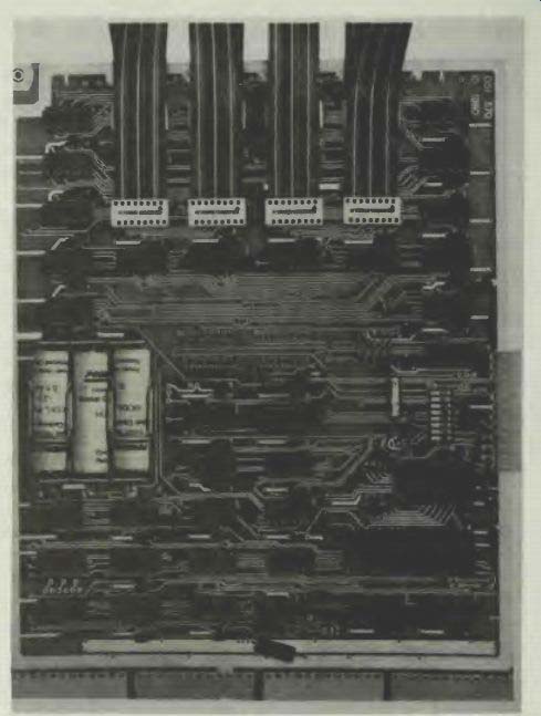
Fig. 5. The Ohio Scientific’s computer circuit board (courtesy Ohio Scientific).
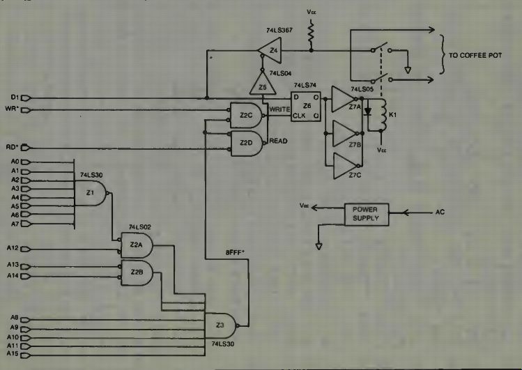
Fig. 6. Memory mapped coffee pot control using the TRS-60 (courtesy Radio
Shack).
THE TRS-80 AND THE OUTSIDE WORLD
We examine the use of the TRS-80 in a control application, courtesy Radio Shack and we can, from the information gleaned, expand our imagination to extend to other applications of such a computer in a robot. It is indicated, in instructions on the use of the TRS-80 in this control type application that external circuitry is required, and also that you will have to have proper software to make the control functioning possible. If you have a Level I machine then you'll have to write the software program. If you have a Level II machine, then you can use the POKE and PEEK or the OUT or IN machine instructions.
It is said that when you design the hardware (circuitry) for computer control of something, you need to have thought out your software program completely so that the two are compatible. How you design your hardware will be deter mined by the instructions you use to operate that hardware.
There are two operational approaches with the TRS-80 (and perhaps other similar microcomputers (which can be used, these are the memory mapped system (Fig. 6) and the second is the port system (Fig. 7). If you use the memory map technique then you must specify a memory address that will be the location of the hardware circuitry controlling your device(s). To write data to your control system (send it instructions) you address it via the address lines and send it the instructions over the data lines.
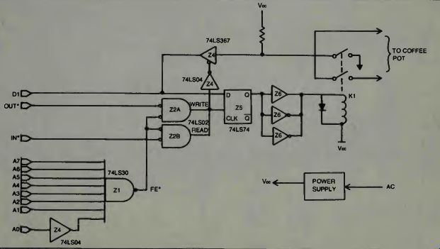
Fig. 7. Torque vs wheel size considerations for robots.
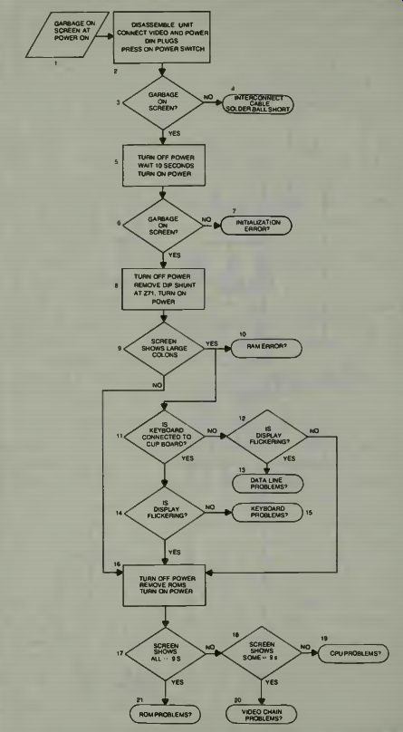
Fig. 8. Section isolation flowchart for TRS-80 (courtesy of Radio Shack).
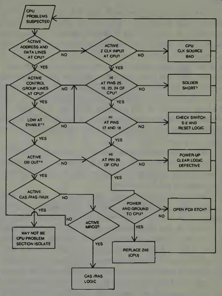
Fig. 9. CPU flowchart for TRS-80 (courtesy of Radio Shack).
One example of control of something external with the TRS-80 is to turn on a coffee pot. A sample program is shown below. At the same time let's look at the circuit for control of this operation.
100 REM ***COFFEE POT POWER CONTROL*** 200 CLS: PRINT@512, "DO YOU WANT THE COFFEE POT TURNED ON"; 300 INPUT A$: IF A$ = "NO" GOTO 7840 400 REM ***IF NO, BRANCH TO "RUNNING LATE" ROUTINE*** 500 REM ***ANYTHING ELSE, TURN ON COFFEE POT RELAY*** 600 POKE - 4092,2 700 REM ***NOW TEST IF CONTROL RELAY CHANGED STATES*** 800 B=2: A-PEEK - 4096 900 IF A AND B = 0 THEN GOTO 1980 ELSE GOTO 3744 1000 REM ***IF RELAY WORKED, BRANCH TO "WEATHER SENSOR" ROUTINE** 1100 REM ***IF RELAY DID NOT WORK, BRANCH TO "SYSTEM FAULT ISOLATE"***
Look at what happens in the memory mapped system. If the address is 8FFF (Hex) and binary data 02 will turn the circuit on by causing the control relay to close. A POKE statement for this task would be POKE 36863,2. In the port based system you specify a port address out of the 256 ports the CPU will address. The address is selected using only 8 lines instead of the 16 lines used in the memory mapped system. The data bus is still used to get information to and from the CPU and the selected port. If the system had used a port based type of control, some of the program above would have to be changed, for example: Lines 600,800 will have to be changed. Line 600 would read OUT 254,2 and line 800 would be: B = 2: A = INP 254. The flowcharts for both methods are Figs. 8 and 9.
PLANNING A ROBOT
The first step is to write down what you want the machine to do. This can take a multitude of thoughts and statements in some cases, and only one statement in other cases. For example, one person had the initial objective "I want a robotic machine which will entertain people." And from that basis he did construct a robot which did exactly that, and delightfully so. There is quite a difference in what you will want to incorporate into the machine if it is for entertainment rather than being built to do some specific task. One machine might be much more complex than another, and how it is controlled may be vastly different depending upon what it is to do.
You will immediately add that the appearance of the machine will, or might be, governed by what it is to do, and you would be exactly right. For entertainment purposes we might want a robot which looks manlike, or girl-like, but for job purposes, such as taking objects from one place to another, the robot might better resemble a small car with a flat bed on it and have somewhat different arms which load and unload the material, than those found on the kind-of human-duplicate the entertainment robot might be. So, when thinking about what the machine is to do, or to state the purpose for building the machine, you will probably also be thinking about what it might look like in the finished version.
This is a second step.
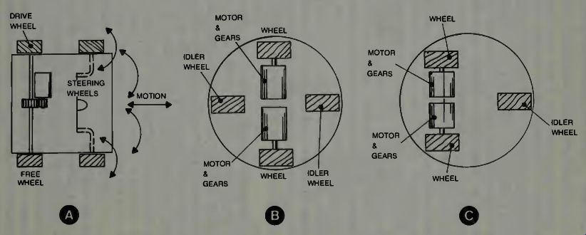

Fig. 10. Some ideas and sketches of possible robotic base-structure mobility
methods.
Next, and closely associated with the previous thinking, will come those thoughts related to mobility. We can make some doodling sketches as we have done in Fig. 10 which may assist us in our thinking.
You can expand on this concept and come up with, perhaps, a dozen different possible illustrations of how a baseplate of a robot might be made and how it might be propelled. In our illustration at A we show a conventional drive using a common axle and one drive motor for one rear wheel. This is important because you can't get the robot around a corner if you make both rear wheels a drive type.
One must be free, that is, its hole slightly larger than the axle so it can turn freely and on its own. The other wheel is fixed rigidly to the axle or so mounted that a gear can be attached to it and this gear is meshed with the motor drive gear to propel the baseplate (and robot). The steering is just like any automobile steering, or toy car or truck, using a turning motion for both front wheels which are linked together. This will work, but the robot may have some problems because the turning radius of the base is large. It is a stable base, however, and can carry lots of weight as we know.
At B is a diagram showing two independent motors driving two wheels, and use of small idler wheels, front and rear, to give the platform balance. This type system is commonly used when you have stepping motors for drive power.
If you step the drive motors at the same speed the base goes straight forward (or backward). If you step the motors at different speeds, a turning motion results. Stepping one motor forward and the other backward at the same speed gives a very tight turning circle. It is easy to synchronize the speed of stepping motors just by observation. If the robot starts to turn somewhat as it goes forward, you just move the control (assuming radio control) of the slow motor to increase its pulsing rate slightly and synchronism is quickly obtained.
The GARCAN robot which we discussed in an earlier section uses this system.
At C of Fig. 10 you see how one idler wheel has been removed. The platform is not as stable as before, but can be all right for level floor operation. Also, if you want to try to use the idler wheel as a drive wheel, this is possible, and you can so arrange the mechanics of the system that the one driven wheel can be turned for steering purposes. You might use a single motor in that case. Or with the three wheeled configuration you might use a single motor to drive both rear wheels as in (A), or use two stepping motors. There are many variations.
So, you doodle and try to come up with some kind of a base-and-drive-and-steering system for your robot, if it is to have mobility. Of course, not all robots (domesticated types) will need mobility. They may be permanent fixtures in the house wall section somewhere, yet they can control all kinds of functions around, and in, and from the home. These are decisions which you must make in your planning.
You can select a wheel size and from that as a starting point calculate the gearing needed and the motor horsepower and so on. You select the wheel diameter based on where the robot is to move. If the surface is smooth and has little change in level, then a relatively small wheel size, say 4 to 6 inches diameter might be all right. But, if you plan the robot going into grass or on rough terrain or unpaved streets and sidewalks and such, then a larger wheel diameter is necessary, say 12 to 18 inches might not be unreasonable. Some may argue this point so we won't say it is required, we just say the larger the wheel diameter the easier it is for the wheel to get over small rocks, and thick grass, and earth depressions and indentations.
But there is a torque penalty as you increase the size of the wheel which is driven. In Fig. 11 we show this relationship, again on a doodling basis. In A you see a large wheel with a given size gear drive. Notice that the forces retarding motion will be the resistance or opposing force (torque) times the lever arm to the wheel rim from its axle. Now the motor torque must, at least, equal this value, and here its lever arm is much smaller, so where do we get the higher number to make equality? We have to get a larger motor torque value than the opposing torque value. The length of the torque arrows (vectors) illustrate this. Now examine B where a smaller wheel is shown, the lever arm is smaller for the opposing torque so the frictional retarding force may be less, thus the motor drive torque needed is less. This is one effect of using a large wheel vs. the use of a small wheel. Notice also the rock in the path of the wheels. For the small wheel it is a high obstacle, for the large wheel, it is not too large an obstacle. The larger wheel may go over the rock, the smaller wheel may not.
In our planning, then, we come up with something as to its size, what it is to do, how we will steer it or control it, or have some notion that it might steer itself, and then we doodle a little, trying to see how and what we want to put together to make it, and from this initial effort we find out other things we need to research and look into to determine how we will put our robot together. We will have looked at where it will operate.
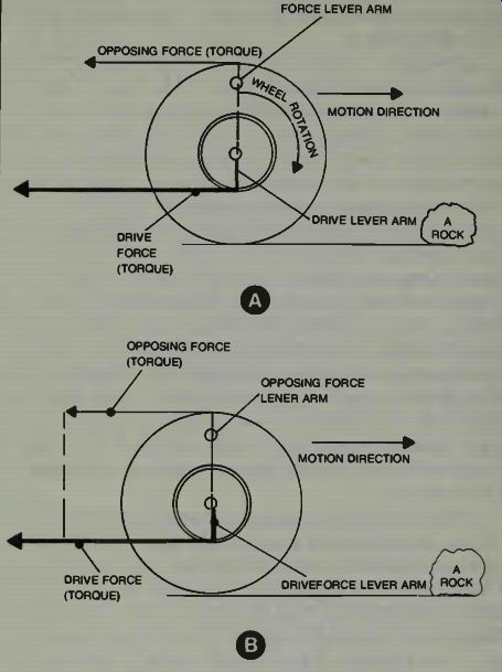
Fig. 11. Torque versus wheel size considerations for robots.
AFTER MOBILITY AND STEERING, THEN WHAT?
That's a good question. You might not have finished with the steering planning, even if you have decided, approximately how you are going to make your robot move and what power supply you'll use and so on. You might be thinking that you'd like to have the robot autonomous, and so that means that some of the steering, at least, must be done by a computer type electronics device. We don't say a computer directly because most have display screens, and maybe disk memories and such, which you actually may not need. They also have keyboard inputs which may or may not be appropriate to your planning. Actually, what you may want for your robot may be more of a comparison type system with memory banks, which can be programmed, and with sensor inputs from all the various devices you imagine might be useful to the machine. It would be nice if you have a kind of plug-in keyboard which you can connect to the robot via a cable, and through which you can adjust its memory. By adjust we mean program, erase and re-program, as you make command changes, and put in directions.
We have examined how a robot is taught in an industrial application. He is "programmed" through certain maneuvers using a small hand-held controller. The electronic circuits are so arranged that as long as the arm is in movement, the computer does not remember what it is doing, but when the arm stops for any period of time, the computer makes a note of this. Later, when the arm is under autonomous computer control, the computer sends the arm to the various end points precisely, quickly, and directly and the arm path may not be the one you used to get it there. It might be possible to easily program a hobby robot much in the same manner but using a radio-control system as the hand-held controller. Suppose we consider that in your robot you will have a radio control receiver whose output goes to a computer and various devices to be controlled, Radio-control systems such as are used in model airplanes can be obtained with up to 8 or so channels. If you need more than that, use two systems, operating on different radio frequencies.
Of course you might also use a hand-held controller with lots of push buttons, attached to a cable system which can plug-into the robot's body, and you can follow the robot as you command it to do whatever you want it to do. The signals could be recorded on some kind of tape, or placed in the memory of a computing section or whatever and then played back later.
MORE CHEAP SPEECH
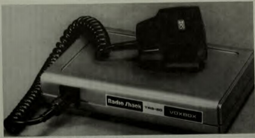
Fig. 12
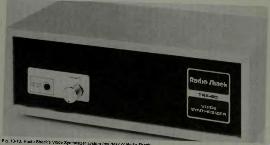
Fig. 13
To know what is on the shelf in the way of equipment which you might use in a hobby or industrial type robot is often very helpful. Thus we call attention to the Radio Shack Voxbox and Voice Synthesizer shown in Figs. 12, 13.
The Synthesizer allows the computer to "say" anything built from phonemes. The Voxbox is designed to work with the TRS-80 computer and is designed with a 32 word memory which permits it to remember 32 words which you teach it, and produce a logic output when such words are spoken to it.
Through the courtesy of Radio Shack we show the block diagram of the Voxbox in Fig. 14.
COSTS AND ACCOMPLISHMENTS
It has been said by many who are experts in the field of human studies that humanity cannot be happy unless they can accomplish something. In fact, this is one fear of those who think about such things-that the age of robotics will deprive persons of doing something worthwhile--in other words, working. Every job performed, in spite of its problems and frustrations and exhausting demands, means that someone has done something which they consider worthwhile. The sociologists think that this, perhaps, has meaning for the happiness and contentment of the human race. Thus, when we evaluate what we have when we have finished our hobby robot, whatever type it may be, we must evaluate our efforts in more terms than just of money or time spent. We must also, always, evaluate in terms of what has been learned and in terms of pleasure received, and personal satisfaction obtained.


Fig. 14. The Voxbox block diagram (courtesy of Radio Shack).
There are very few if any, persons, who will say, directly, that the future does not hold a place for industrial robots.
There are too many foreign countries developing such devices for use in their areas of productivity. And with such success that our own industrial leaders say that a clear view of those operations. Much planning and consideration must go into the concept of using more automation in existing plants, because of the worker commitment to the various jobs. Yet the profit motive, being the primary reason for the existence of the plant or industry in the first place, will demand the most economical, efficient, and productive operation possible at the smallest possible costs. Let us examine what might be some of the consideration for the use of industrial robots.
Do they contribute to productivity, efficiency, reduction of error, a better product, faster production, reduce hazardous situations, reduce tedium, improve the work environment, reduce costs? In many cases this requires a complete review of the whole operation, down to the most minute detail, of the business, or plant, or industry wherein the use of industrial robots is being considered. We are in mind of a system of plan evaluation or job operation planning called PERT (Program Review and Analysis Techniques) or, as it is called by some, the critical path planning approach to- whatever job or task or operation is in mind. Can it help show the need for automation or robotics?
WHAT IS THE CRITICAL PATH APPROACH
If we take the start and end of a series of tasks and call them events, and we take the activities in between the start and end of each such task and call that an activity, we can make a diagram showing this concept as illustrated in Fig. 15.
Notice that there are many activities (arrows) shown, 5 in total. Also know that it will take the completion of all 5 activities before the end event can be said to be done! At this point we do not know from whence the other activities originate, or how they may be inter-related, or interdependent upon other end events, but be assured that in our modern industrial world, there will be a rather complex network before we come to that stage where the end event actually means the completion of the job!
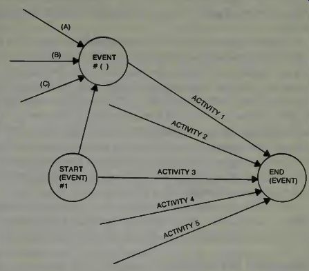
Fig. 15. Some pert or critical path definitions.
The starting event can be merely a time and date at which some activity begins. The end event can be a time and date when the job is finished. The activity can have a length which is somehow related to the time it will take to do that activity, based on the educated guesses of many experienced personnel who have some knowledge and, hopefully, experience with doing that kind of activity. Thus we might say activity #3 will take 4 days to complete, by best estimates.
Think what this means if it is required that all the other activities must be done within that same time frame in order for the end event to properly occur on time! As you might look over the time and date estimates of each activity, you might find one which is so long that it is a bottleneck. It will be that long-time activity which will hold up the job which needs some attention. The path through that activity from its starting event, to the end event, is the path known as the critical path. It is a trouble area for some reason. It is stated that this critical path is the one which requires the most time for any process or object to get from the initial event to the end event.
Also, it is stated that if there is any further delay along this critical path, then the final event will be delayed by whatever time the delay on the critical path assumes.
So, how do we relate this to robotics in an industrial sense? If we consider an example where lots of parts must arrive at a given station at a given time in order for assembly to be accomplished, and that a delay is found on one path, we will assume a simple case here, wherein the distance the part has to move, and the processes which have to be accomplished on this part, are responsible for that delay, then we can see how an automated situation may remedy the problem. It is not unreasonable to think of robots doing the processing, and perhaps saving time doing so. It is not unreasonable to think of robotic conveyors transferring the parts more quickly. Thus we change what was a critical path for the parts movement, into a non-critical path and every thing is accomplished in the required time and lots of profit results! There are many approaches to consider when trying to make a decision as to whether or not to robotize some, or all, of your operations. There are many things to consider. For example, you must always have in mind what will happen if a machine fails. No one likes to think of this, but it can and does happen. We are reminded of a situation wherein some robots failed because the human attendant did not keep the hydraulic oil tank filled properly, nor did he (she) report leaks which had been observed, etc. It was determined that it was that worrisome case of a human hating a robot and thus hoping it would cause trouble and helped it to do so! There is no question but that, in some cases, the robot will displace humans in certain work functions and activities.
It is just an axiom but for some things, robots can do it better.
CONSULTING THE EXPERTS
Of course this is done. One just doesn't expect all the people in his own operation to, necessarily, know all about robots and robotic installations, and operation and maintenance and what can and what cannot be done with these machines. Sometimes, and this is true in most cases, an analysis of your operation by a robotic expert will help to show what should or should not be done. However, one must always consider that probably any representative from any robot manufacturing company will be a salesman. But most will give a good, honest, and reliable report on the situation at hand.
Because a conversion to industrial robots is an expensive operation, probably in more ways than just changing equipment, management will also want to inspect and discuss robot plants with those who have already done this in part, or, as some Japanese have done, completely robotized a plant or industrial operation. One question which always comes to mind is, "What do you do if some machine fails or stops, and it is a line item which must function in order for the whole operation to function?" First, of course, there needs to be an alarm system. We have mentioned this in some previous pages while discussing industrial robots. The alarm can be of several levels. One, a warning that trouble is imminent, and where it might occur, second, that trouble is happening and where and why (sensors can determine this in many cases), and what should be done about it: a rerouting, stopping all machines, or whatever is appropriate, even to the extent of human intervention and human substitution for the machine until the robot is fixed.
There are many other items which need be considered, such as a loss of electric power, even for just a short period of time, and how this might affect computer programs, movement, and synchronization and so on. One might use the operating room technique wherein a substitute power plant comes on immediately in case the main source of power starts to fail. When consulting the experts in the field, one will become knowledgeable of these various situations and problem solutions for these situations. It is also considered good management if one can obtain the help and advice of the normal plant complement of persons, who can give suggestions which will make their job work easier or more palatable, and thus they provide insight into possible areas of automation which will be accepted by them. Education and instruction of plant personnel is, of course, mandatory. The experts can help with this type of public relations.
ROBOTS AROUND THE WORLD
It is also interesting to consider the robotic development of some foreign industrialists. A study by Professor Gustaving of Bradley University states that Japan has 13,000 of the world's 17,500 industrial robots. They have some 70 companies who are developing new robots and this compares with some 27 companies in the U.S. It has been reaffirmed that the Japanese goal is still the unmanned, robot operated factory.
The progress in industrial robotics has been remarkable and will continue at an astonishing pace. It has been said that the new robots are simply programmable arms with some high degree of manipulative skill. But that they have poor senses and a somewhat low intelligence which is not yet able to comprehend and really handle the information which is presented by the various types of sensors. But that even so they are most valuable in industry. It is not uncommon for industrialists to recover their capital investment in robots in somewhat under three years.
It has been pointed out that robots need something better than the type of grippers which are now common. But these improvements are under research and development, especially in Japan and in Russia. Robots which have fingers that can handle objects as delicate as an egg without any danger of rupture, and quickly adapt to different and varied object forms have been made. It has been stated in various studies that one of the most valuable ways a robot can improve plant production is by speeding materials through a plant. It was found that materials are worked on only some 5% of the time, and the rest of the time that material is lying idle or being transferred from one place to another. When robots are specifically designed for a task, they can offer some very remarkable work. For example, the Fiat Robogate, installed in its Rivolta and Cassino factories is said to be able to accomplish all the required welds on a car body in less than one minute. There are more than 50 robots on each welding bay. The precision of each job is the same so that quality control problems are reduced, and should improvements be needed, a slight change to the control program affects the desired result.
The use of robots on an assembly line seems to be inevitable and no matter what the task, it now seems possible that the job can be done by such automated machines. The human system seems to break down when subjected to the constant boredom of doing the same task over, hour after hour, day after day. It was found that in Silicon Valley of California where chips or integrated circuits are developed and made, that this type boredom has led to such advanced human problems as drug usage. That, of course means profit loss to management in that quality is sacrificed, and integrity of the firm or plant is jeopardized. That means a loss of buyer confidence. Again, here, in this type environment and task situation the robot type machine offers no such problem. It does what it is programmed to do (what it has been taught) endlessly, hours on end, without error, loss of quality, or complaint.
As robotics components are developed and improved, such as the new TV cameras-on-a-chip developed by Hughes Aircraft Company using the new advanced charge-coupled technology which we have discussed somewhat in earlier pages on robotic eyes, the ability of the robot to do more things better will be almost beyond imagination. These Hughes Omneyes, as they are called, consist of a chip of some 1,024 light-sensing elements for one type application, and another chip with some 10,000 picture elements for higher resolution. It is envisioned that the ultimate use of these robotic eyes will be on the assembly lines to help the machines size, orient and identify parts and objects. Because of their small size and low power requirements, they can be used close-up if necessary on smaller and smaller type objects, perhaps ultimately, even down to integrated circuits themselves.
JOBS
When one considers the use of robots in a factory or plant the questions and job-loss fear of employees, and Management's commitment to the workers, becomes very real situations to deal with. Some questions asked by workers are, "Will robots in factories eliminate jobs?" The answer, of course is, yes. The robots will eliminate a majority of the old, dull, hazardous, and non-progressive jobs. But, if one is willing to learn and adapt to a new world of robotics, then there are opportunities which one should consider. The following comes from a study conducted on Careers in Robotized Factories.
Robots need repair sooner or later. Robot repairmen will be in high demand and will be very well paid. These personnel will also check and test the robots to insure maximum performance with a minimum of breakdown. There will be robot trainers, i.e., those who program the robots, and that will be a field in which computer knowledge and new skills in machine programming will be learned at special schools provided by the user plant or the robot manufacturer. There will be those who will be responsible for moving the robots to desired workplaces if the robots are the fixed location types. These persons will coordinate the robot's work load, and will see to it that they are productive at their new line locations. Of course there will be more and more need for robot designers.
These persons who have engineering backgrounds in control and electronics and mechanical engineering and physics will obtain very high salaries and find their work challenging and very productive. Industrial robot use and plant analysis may be another rewarding career field in which people, sociological problems and machinery are all considered together. It is going to be a long, long time before robots will be able to repair and adjust and teach themselves much more than very elementary operations. So they will need lots of care, adjustment and help.
The respected Wall Street Journal has reported that some factories in which robots are built by other robotic machines without human control, have been under construction by some Japanese electronics firms. This has been the beginning of a deep seated fear of job loss among many people who are not knowledgeable about such machines. It is entirely feasible to specify, down to the smallest detail, the parts and layouts and connections of those parts, to make up a robot, and then to design machines which will do the assembly work so that at the end of the assembly line, a so called robot will appear, ready to go to work.
Are robots on the increase in industry? Ransberg and Renault have formed a venture to make and deliver industrial robots with each system selling at $100,000 to $200,000 each.
It is said that they have invested some 15 million dollars into this venture. The chairman of the Ransburg Corp. (France) has estimated that the U.S. market for industrial robots is expected to be in the vicinity of $500 million dollars annually by 1985.
If there is a process in a factory or plant or industrial complex which cannot be robotized, it is just because no one has examined it yet for that purpose. The many fine robotics companies are leaping ahead, year after year, with advanced and improved designs as the technological explosion continues, and there seems to be no end in sight. It may well be that in the not too distance future, factories and plants and industrial complexes and shops and stores and assembly places and whatever will have to consider using robots in self defense-in self defense of profits, that is.
THE COMPUTERIZED HOME AND ITS SECURITY AND CONTROLS
The computerized home might also be called a robotic home. What is a robotic home? It is a home in which there are many automated devices which make that home more secure, easy to keep, and pleasurable for you to live in. In a sense this means that you will make your entire house a kind of robot and you will live in its protective embrace.
On the practical side, of course, what we mean is that your home will have some kind of centralized computer which can sense and control a multitude of functions in and around the house. One such computer is the Scientific Instrument's C8P which we use for an example here, although there are many other types which can also do this kind of job (a job is an action requiring many tasks) for you. Briefly, here are a few other control items.
With the speech capability, the person might not have to touch a bar at all. They simply say "Return" and this activates the return program in the computer. Or they could say "Help", and this would activate another computerized sub program which would sound an alarm and indicate where the trouble exists. We have previously stated that such things are possible. We look at Fig. 16 to see one example of a voice system produced by Ohio Scientific in their CA-14A system.
When you want to make things happen in the house, such as to turn on the coffee pot, and turn on and off various lights and other electrically operated devices, you need a kind of special type computer unit and remote controlled modules.
One example of this type system is shown in Fig. 17.
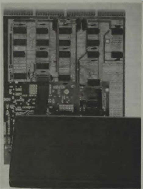
Fig. 16. Votrax, a voice system produced by Ohio Scientific in their CA-14A
system.
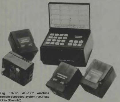
Fig. 17
The master control unit is so programmed that when you press down the various buttons you can cause the circuits controlled by the modules to energize, thus you turn on lights at will from a remote location. Again, using the button controls, you can deactivate those remote circuits also. Since the control signals are sent over the house wiring, it is no task at all to install such units, you simply plug-in the remote modules into a convenient electric outlet, and run the cord from the master box to the outlet in your remote command location. You plug-in the devices you wish to control into the modules receptacles and you are ready to operate. By the way, don't do as some do, they plug in lights but forget to turn the switch on. When the signal is sent from the remote location to energize that light (or whatever), it won't work, because its own switch is off. There is a unit made that interfaces this system to a TRS-80. In this robotic home concept we must not forget the possibility of remote control, from some pleasant beach re sort to our homes back in our own home town. Yes, it is possible and feasible when we use a device called a telephone interface such as is shown in Fig. 18.
Looks complex, doesn't it. It is. But that is no problem to us. When this is connected so the telephone has an input to it you can communicate with your home computer from almost any place in the world. If your telephone system is a Touchtone phone you can obtain status reports on various things in the home when you send certain coded groups of numbers which the computer can recognize and respond to.
For example, you can tell the computer to water your plants, give you a report on the integrity of your windows and doors, test the air for smoke or other bad odors, also to play back for you, any recorded messages which are on file in the telephone message recording machine.
With appropriate sensors you might get a report on the grass height and the dryness of the ground. If the grass needs watering, then you can tell the computer to water, using the robotic sprinkling system, for a specified period of time.
Imagine also that you found the grass too high, in your status report. You simply send in a new series of coded numbers and the computer will order the robot lawnmower into action. It will cut the grass, following a carefully prearranged routine path route and then return itself to its garage home or wherever. It could be that in the future all mail will be electronic.
When you query from Hawaii or elsewhere the computer will tell you to pay such and such bills and ask you if it is all right for it to issue the checks! Yes, 'tis true, all things are possible nowadays in our computerized, robotic world.
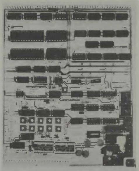
Fig. 18. CA-15 Universal Telephone Interface (courtesy Ohio Scientific).
SOME STEPS IN ROBOTIC DESIGN
Be it hobby type or industrial type, there are certain steps which are generally followed in the design of robots.
These can be listed as follows:
(a) List the functions desired to be accomplished-what it is to do now and in the future.
(b) Draw block diagrams showing the interconnection of various units such as drive system, signal processor, etc. Use as many block diagrams as necessary to come up with some kind of complete picture of the machine.
(c) Check the availability of the parts needed for each block of your block diagram. If some parts are not available then improvise, invent, construct, or change the system in that block.
(d) Construct breadboards of your circuits and test them, adjust them and modify them until you get the necessary and correct operation from each board reliably and repeatably.
(e) Construct models (miniatures) of all moving, working parts. Check for construction difficulties, needed materials, and make such changes as necessary to accomplish the end objective for each unit. Test and adjust each unit.
(f) Construct a full size working model of the robot- leaving room physically for changes and modifications- being sure you have easy access to parts and test ports. Check the operation of each unit and the complete assembly.
(g) Construct the final package which has the desired shape, size, and appearance you want. Test and adjust it.
Operate it, or let it operate itself. Check for faults and reliability. Study it for improvements. Then, have fun!