AMAZON multi-meters discounts AMAZON oscilloscope discounts
He is called GARCAN, and he is manufactured and displayed by Jerry Rebman Electronics Co. They can supply all parts for this type robot. He is a toy-like being that is capable of wheeling around at parties and on display floors, under the able and capable radio control guidance of his master, Jerry Rebman, and he can converse with attendees either in groups or single units. He can entertain with songs of any type, or other 8-track recorded sound, through his concealed, high fidelity speaker system. His purpose in life is to entertain and to do this, like his human actor counterparts, he can change his costume, and thus his identity, as simply as donning a new outer shell covering.
GARCAN is a rugged unit and can withstand the pressures of children climbing up on his "garbage can" working costume without sustaining damage. He has provided amusement and entertainment for the most elaborate of high society affairs, as well as for those youngsters who are con fined in hospitals for all the well known, but little understood, reasons. His manner of speaking, at the moment, is through a intercom unit which permits his master to listen to and talk back to anyone who says anything to GARCAN when he is "on the job," except, of course, during those moments when GARCAN's internal tape player has been activated.
My first encounter with this delightful unit is illustrated in Fig. 1. I had been invited to the home of Jerry Rebman and after a few moments he vanished outside this lovely family room. A moment later, to the tune of purring electric motors, GARCAN appeared in the doorway and with uncanny accuracy and agility entered the room, flashed his "head" lights at me, decided I was friendly and came closer (Fig. 2). There he stopped and silently examined me and all the while I watched the maze of lights flash like small bits of lightning under his plastic, hemispheric, domed head-space. I noted his rugged construction and how well the inverted 30 gallon garbage can made a suitable body when mounted on the circular, one inch thick wood or composition board base platform. I could just barely see the front idler wheel which gave the base platform good stability. I assumed, and correctly, that there would be two other wheels located further to the rear of the platform and that these would not only provide mobility, but also steering. I also noted how easily GARCAN moved across the bare floor and the thick carpet.
There are countless types of display robots being used now at expositions, fairs, on TV, in movies, at parties and such, and it is safe to say that 98% of these are radio control led types. They may be more elaborate than GARCAN, who is a paraplegic (no arms at present) because the addition of arms means much more complexity. Others may have arms and wrists and hands, but these are all operated by control signals sent from behind one-way windows in exposition booths.
Display robots of this type may also have a multitude of self contained sub-programs which can be started or stopped by radio signals, and these may range from a pre-programmed path movement, to animated arm and finger movements, to speech delivery, to music, to display of TV pictures on a special built-in screen. We have found that the big companies such as GE and Hughes and others have used such display robots to present their messages or logos to the public at various functions.
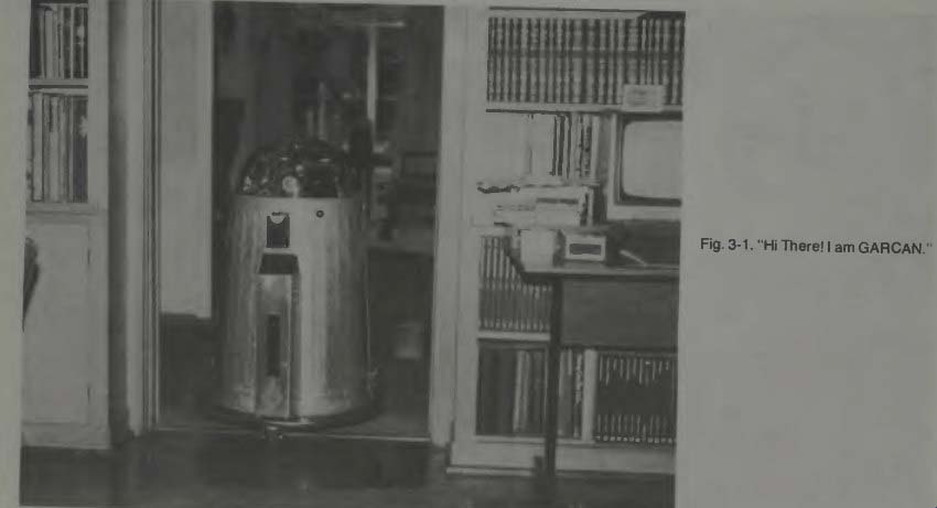
Fig. 1.
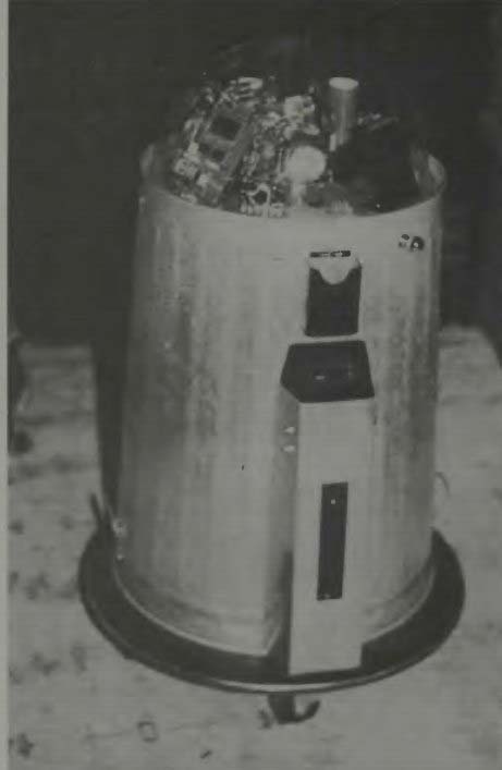
Fig. 2. "Well, look me over!" Display robots are a reasonably
big business and will be a larger business activity as time progresses. They
cost from 4 to 10,000 dollars each and they rent, with a Robot Master, from
$50.00 an hour upward after expenses are paid. Some types are "quickly-put-together" units
for profit, and some are well built scientific experiments. In the display
robot role, these units have but one purpose for their existence; to entertain,
amaze, and delight those who see them. One way in which this amazement is encouraged
is to add flashing lights or other eye-catching devices which are clearly visible,
under protective covers, and which seem, or even may really be, a part of the
robot's internal control system.
We examine GARCAN closely because he gives us a good insight as to what makes one robot "tick." He is a well engineered model, and a person might expand his basic system to include a multitude of sensors, computerized control, TV eyes and such, if one is inclined toward experimentation or design in this direction.
EXAMINING THE INSIDE OF GARCAN
Now we examine the inside of GARCAN. It is easy to loosen three bolts which hold the inverted garbage can in place on the circular base structure. There is a multitude of wires running from the base electronics to switches and electronics inside the bubble-head. One has to be careful to lay the garbage can down right next to the base as shown in Fig. 3. Another view of the two parts can be seen in Fig. 4, and a good view of the internal wiring is shown in Fig. 5.
Notice that there is lots of space should one desire to add arms and the arm mechanisms. No attempt had been made to cable the wiring and there are no special wires except one. A wire from the radio receiver, located in the bubble, which comes down to the motor control unit is a coaxial type. Coax prevents stray signal pickup which could influence the control, steering, or drive signals to the base mounted elements.
In Fig. 6 Mr. Rebman points out a particular circuit holding a standard radio control transmitter such as made by Heath Co., ACE Electronics, Kraft, etc. The second robot is wearing an armadillo suit covering. The electronics for the two robots are identical, but different RC frequencies are used for control so both may be operated simultaneously.
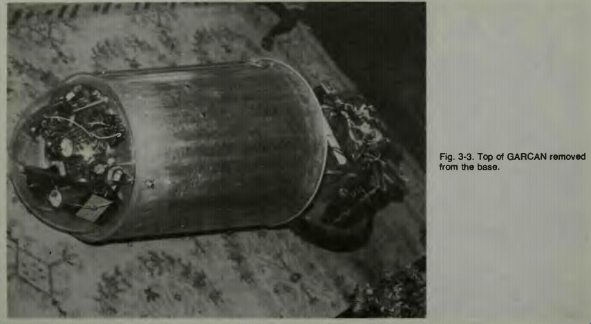
Fig. 3
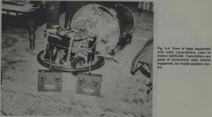
Fig. 4
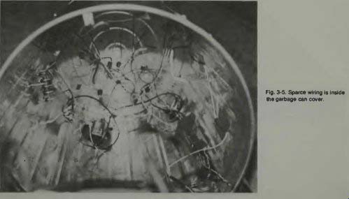
Fig. 5
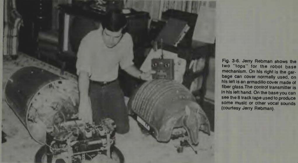
Fig. 6
There are many other covers which can be used with the base platform. One is a snowman, another is a Christmas tree. The armadillo covering is made of fiberglass, and on this robot there is a forward jutting arm which is used to prevent the robot from damaging its head if it happens to run into something. On the reverse end of the covering is a tail. This has no electronic purpose or defensive purpose but is for effect only. Because he is such a pet, the smaller armadillo has been given the special name Minidillo, and he is shown in closer view in Fig. 7.
INSIDE THE ROBOT BASE STRUCTURE
We look at a view of the base structure in Fig. 8 and we can see how one drive motor and two steering wheels have been mounted. The wheels project through the base. We can see that the one on our right is connected to a electric bicycle motor (1/4 horsepower) by means of a chain and some sprocket gears. Each wheel you see here has its own motor.
With the swiveled front wheel, the three wheels will form a triangle with a wide enough span so that very good stability is achieved for the vertical structure. Also, not visible in this photograph, but present, is a deep charge 12 volt automobile type battery which is located just behind the front wheel and just to the rear of the tape cartridge shown. Jerry informs us that it is very important to get a deep charge type battery as the motors draw some 30 amperes when stalled, and about 5 to 6 amperes when running, and so for operation over any length of time a really good battery is needed to supply motive power. This same battery, with voltage reduced and regulated to a value of about 4.8 volts, is used to power the radio receiver, and the radio control servos.
Switches control the larger power flow for the tape deck and lights and such.
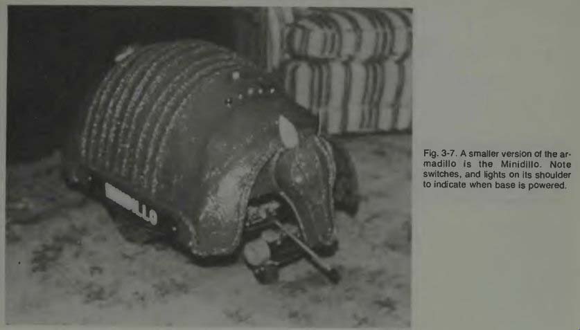
Fig. 7
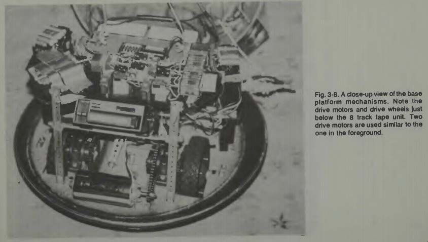
Fig. 8
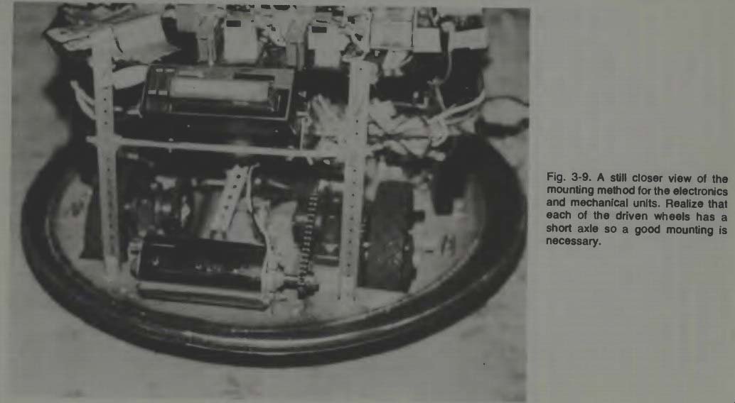
Fig. 9
Since motive power is such an important first feature of any robot of this type, we get even closer through Fig. 9 to the motors and drive mechanism. Each rear wheel has an identical chain drive and an identical electric motor of the type shown. The speed of each motor is controlled independently by radio command through the radio control transmitter held by the Robot Master.
I wondered if it was a problem to synchronize the motors to get forward travel. This, said Jerry, is not a problem. Since the motors are nearly the same, and since he has independent control over each motor's speed, he can easily-with practice-adjust the RC sticks so that the robot moves for ward or reverses in a straight line. To make the robot turn, you simply advance the speed of one motor while you reduce the speed of the other motor. A tight turn results. It is also interesting that a double gear-reduction via the chain drive sprockets, is used to get the speed of motion down to about a fast walk. Using a gear reduction you increase torque to the wheels and thus the unit is able to operate over thick carpets, grass, normal unevenness in concrete and such. A single wheel for both motive power and steering of such a base platform is not really practical except on smooth surfaces.
The arrangement shown here has turned out best and will prevent tipping of the robot even on a steep grade.
A good side view of how the tape player is mounted, at an angle above the motors, is shown in Fig. 10. You can see that when a given tape is placed in the unit it cannot be changed without removing the body from the robot. This presents no problem, really, as you know ahead of time what kind of tape you want inserted, and the tape is long enough so it doesn't get boring during a demonstration. Another advantage is that you can record your own jokes, stories, or what ever. With the 8-track unit, there is radio-control switching of tracks. You know what's available on all of your tape, and you simply command whatever track is appropriate at that moment. The commands for this function are sent to the regular radio-control servos which are mounted so they open and close the microswitches which operate the tape player, a very reliable and positive method of control.
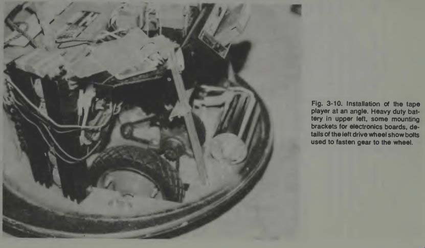
Fig. 10
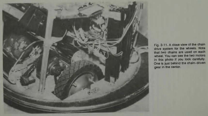
Fig. 11
We can examine the gearing and chain drive system still closer in Fig. 11. Notice that the driving wheels do not turn to accomplish steering. The wheels are fixed in the plane shown by means of rigidly mounted axles. To turn the base, one of these wheels is made to go faster or slower than the other. To the right of the nearest wheel is a black looking vertical stack. This is one of two heat exchanger mountings for the powering transistors for the motors. These transistors get really hot and must be mounted on a heat dispersing base.
The motors themselves also get very warm to the touch, but they operate within the manufacturers specified temperature limits. The wheels are obtained from a hardware store and the gear is bolted to them. Bolt shafts can be seen on the nearest gear, while in the background you can see the relative size of this gear. The chains are smaller than the regular lawn mower type, but very strong.
We have mentioned the use of the regular model airplane servos as mechanisms to control function switching. In Fig. 12 we get a better idea of how this was done. By close examination you can find the little servos with their plastic arms which, when moved by radio command, open or close the microswitch levers on each side of them. These servos and switches are bolted down rigidly to a base plate of plastic and this, in turn is fastened down to the supporting structure above the drive motors. The use of microswitches is important. Since they snap into contact or out of contact, they make a positive connection quickly and thus may prevent burning or pitting of points. Also, since they have a good rating in conductivity, the points are large enough to pass all the current required for the auxiliary items easily and without loss.
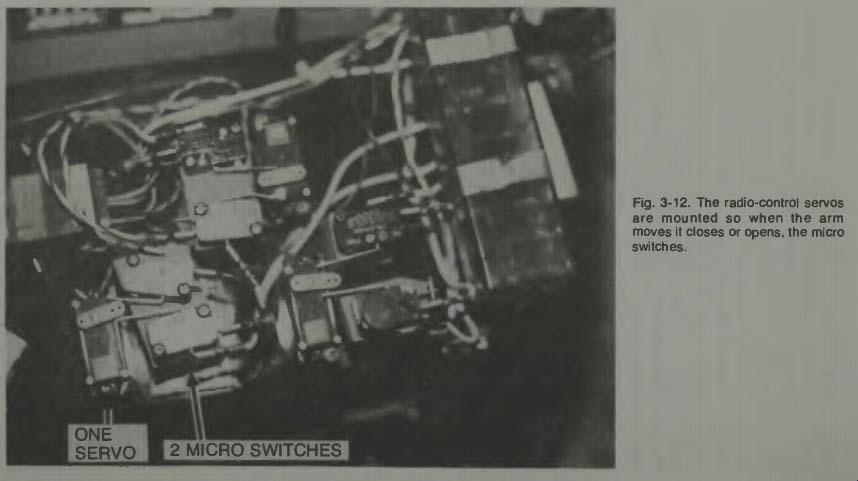
Fig. 12
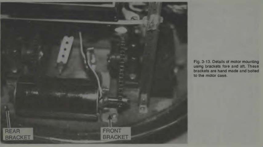
Fig. 13.
Because the driving section of such a robot is usually the biggest problem to those who would fabricate a robot, we take another look at the drive motors and their mounting and the chain link to the wheels in Fig. 13.
In this figure you can see, with a close observation, that each end of the drive motor has been equipped with an L-shaped mounting bracket. This, in turn is bolted down to the baseplate. The use of such a bracket, which is bolted to the motor, prevents the motor housing from rotating as the armature turns. Sometimes you can use a cylinder case on a motor and a strap around it to hold it down but if the strap loosens, you have a motor housing rotating, or trying to, and this causes problems. It is better to bolt a bracket to the motor housing at each end of the motor and then bolt that down to the baseplate as shown. Observe, also, that this is but one of the two drive motors required for steering and motive power of the GARCAN robot.
I have said that the drive transistors used with this motor controller electronics system need to be able to pass high currents which exist when the motor is starting and when various speed changes occur. Going from a stopped position to a full speed (approximately one foot per second) requires a surge of about 30 amperes as opposed to the 6 amperes needed to run the motors. Each motor requires four heavy duty, high current transistors in order to accomplish the switching required to permit variable speed control and re verse motor rotation. These transistors take the place of relays and are more effective than relays in this application.
Since the transistors must be mounted on a heat absorbing and distributing plate, they are mounted separately from the printed circuit board used for the balance of the motor control electronics. We can see four such transistors properly mounted on a vertical metal plate with fins for heat dispersion in Fig. 14. A terminal strip is bolted to the left side of the plate to make connections positive and easy. These transistors get very hot.
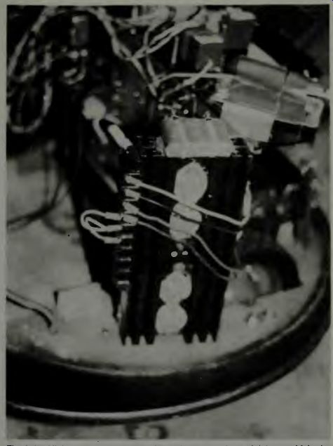
Fig. 14. High current motor control transistors on a heat sink base which
also serves as a support structure.
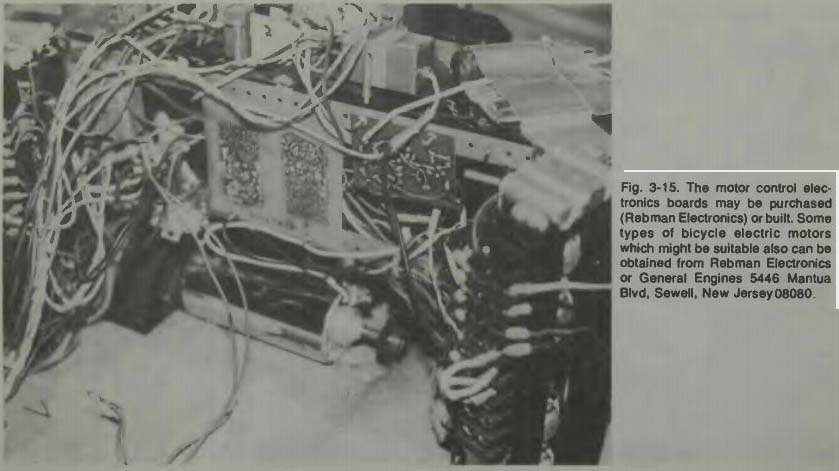
Fig. 15
The balance of the motor control electronics can be seen in Fig. 15, in the center of the baseplate section. The heavy duty 12-volt battery is normally located in the open space toward us and away from the motor. The motor is the second of the two required, and above it you can see the two-section printed circuit board which contains all the necessary electronics to use the signals sent from the radio control transmitter to its receiver -a series of pulses which change their position with respect to one another and a reference in accord with the stick movement on the transmitter. These circuit boards convert these pulse positions into pulses of electric current and feed these to the motors at a much higher current level than the receiver is capable of delivering. The number of these pulses per second determine the motor speed, and the polarity governs the direction of motor rotation. Since two drive-steering motors are required on this robot, two complete motor-control circuits are required, using 2 radio control channels.
Notice that the mounting plates for the transistors are located at each end of the photograph. They are also used as a support for the second story deck on which the small radio control servos and microswitches are mounted, and to which the tape recorder is fastened.
Before examining the circuit concept, we take a look at Fig. 16 for another variation in this type of robot. This is a Tall Boy unit with a high square body mounted to the base plate covering, and with its head bubble located at the top. It stands some six feet tall, is painted black and when it comes into a room it does create some excitement with its flashing lights and strange noises!
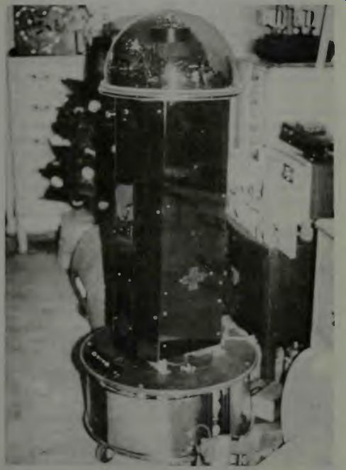
Fig. 16. Jerry Rebman's 6 foot robot (courtesy Jerry Rebman).
We have stated that these robots are paraplegic -no arms. If one decided to add arms, it would require additional motor control circuits and motors. One motor and circuit board would be needed for each arm as a minimum. With this much additional equipment, the robot could be made to raise and lower his arm-or with two such circuits, both arms either singly or simultaneously. No elbows or wrists or grippers would necessarily be used. Two more radio channels than the minimum of three (for motor control right and motor control left and tape unit) would be needed. But one might use an 8-channel RC system (they are available) and cause the closing of more microswitches to open and close pincers etc., if one wanted to experiment in this direction. Also, don't forget that a person might use an 8-channel RC system for many functions with that RC system operating on one frequency and then incorporate a second R C system with another 8 channels operating on a second frequency! Since it would operate on a different frequency no interference would be experienced between the two. As we indicated earlier, the limit as to what you can do with your robot will simply be limited by time, effort, and money!
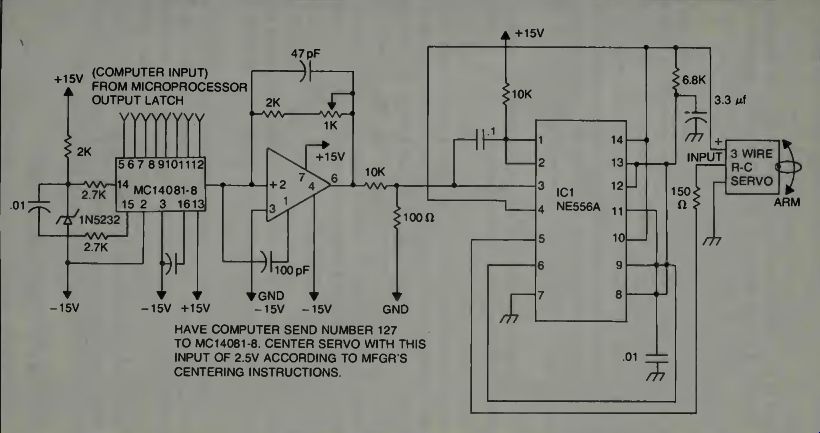
Fig. 17. Driving a model airplane-type servo from a microcomputer (courtesy
Kilobaud).
OPERATION OF GARCAN ELECTRONICS
Figure 17 shows how a computer may be interfaced to drive a small radio-control type servomechanism. The importance of this circuit is that with it, you can interface a computer to control your robot in either an autonomous or a remote state simply by adding additional sections to the GARCAN motor control circuit. Notice that the output of the ICI 556A is driving a standard model airplane 3 wire servo. It provides as output, the type of input necessary for the motor control circuit of one motor of the robot. You would have to experiment with the addition of a second similar circuit, connected to the computer output, or to the MC 14081-8 chip to make a second channel to drive the second drive-steering motor circuit of the robot.
If you are ever to have an autonomous type robot, it will have to have some kind of computer within itself. A domestic android type of household servant will never be achieved without it! The best way to understand how this might be applied to the GARCAN robot, is to examine the following circuits. First take a look at a sketch of the RC transmitter.
From it learn how the various robotic functions are con trolled. Examine Figs. 18 and 19.
Notice that even the voice is controlled by a stick position. When you are steering GARCAN, you will be holding this type transmitter and you will be using the thumb of each hand to position the two sticks. Jerry tells us that with some practice you can control GARCAN easily and accurately. Both thumbs would be working simultaneously as you can imagine.
All radio control bugs will love this type robot! Now study Fig. 20. It might be of help for us to point out that if you do not use the radio control link, then there must be two signals from the digital-to-analog converter. One of these signals must go to the motor controlling circuit. The second signal must go to several standard type RC servo units which control the off-on switching for other functions. A motor for this application should be relatively small, be either permanent magnet or a field wound, 12 volt, direct current motor of about V4 horse power. If the robot you intend to power is much heavier than, say, 100 lbs, then you might think toward a 1/3-horsepower motor. Each motor must be capable of being operated at normal speed and load with an input of around 6 amperes, and its stall current or starting current should not exceed the 25 to 30 ampere range specified for these two motors.
Since we have been discussing the computer addition to the robot control system, it is interesting to look at a small microcomputer system and its disc operating system shown in Fig. 21. You can imagine typing in your commands on the keyboard and transmitting them via radio link to your robot, and if you let your imagination work a little harder, you can imagine the robot's responses appearing on the CRT!
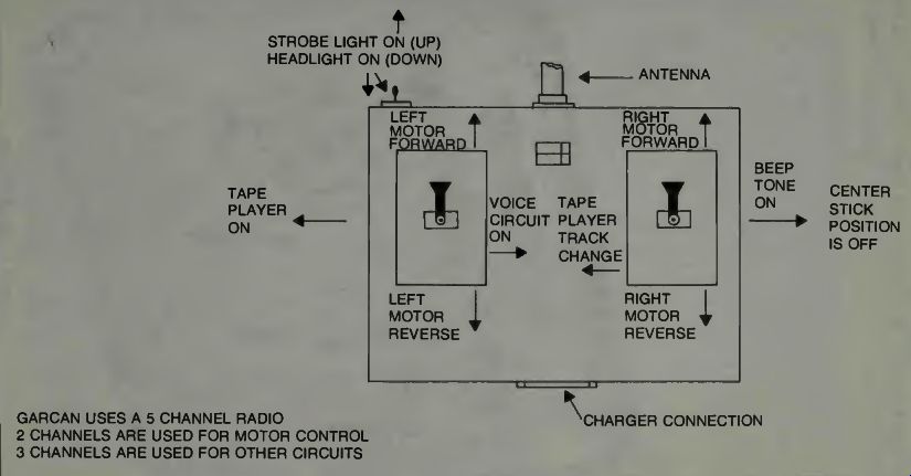
Fig. 18. GARCAN transmitter functions (courtesy Rebman Electronics) .
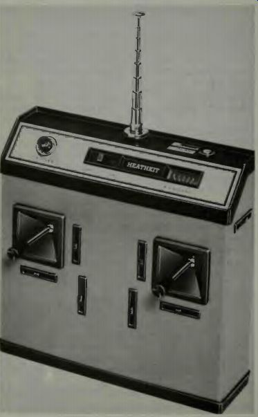
Fig. 19. A commercially available 8 channel RC xmtr.
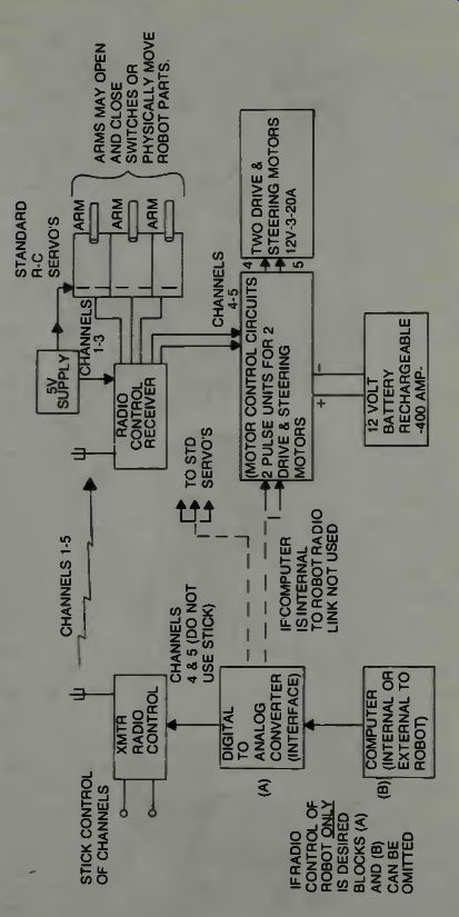
Fig. 20 A General block diagram of an RC directed and computer controlled
robot.
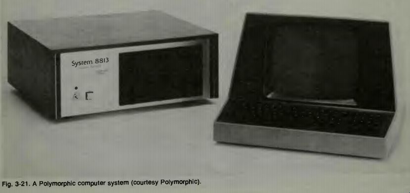
Fig. 21
THE GARCAN MOTOR-CONTROL CIRCUIT
Jerry Rebman Electronics developed this motor control circuit using as a basis, a circuit which appeared in the February, 1978, issue of RC Modeler magazine. The circuit is developed around the NE544 chip made by Signetics Inc.
Extensive modification to the original circuit was required by Rebman Electronics, and it is with their permission that we examine it here. In Figs. 22 and 23 we can see the circuit layout.
From the left side of the diagram, we find the input which has been prepared for positive pulses. Some RC transmitters and receivers use a negative pulse arrangement. There are circuits which convert those negative pulses to positive pulses and ACE Radio Control is one place where such con version circuits might be obtained.
=========
PARTS LIST

Fig. 22. The Motor control circuit for GARCAN. Two such circuits are required,
one for each drive-steering motor (courtesy Rebman Electronics).
==========
Next we find the ground, or common connection and at the top the 5-volt positive input supply line. Notice that the ground connection is common to both the 5-volt supply and 12-volt supply. Both supplies must have a common ground.
The input pulses, varying in spatial position, or time position, in accordance with desired commands, are input to terminal 4 of the chip. Thence the chip's connections are made to various resistor-capacitor arrangements among which will be seen the trim pot and the range pot, two important adjustments. The trim pot is used to set the motor speed to zero when the transmitter control stick is at neutral.
Refer back to Fig. 18 and see how the motor changes its direction of rotation as the stick is moved up, or moved down.
When both sticks are at the center or neutral position, neither motor runs and so the robot stands still. The range pot governs how quickly current is applied to the motor. This, then, in turn, governs how quickly the robot will start to move when you move the stick from the neutral position. You simply have to adjust this potentiometer to your own requirement. You don't want the robot jumping forward, and you don't want to have to wait a long time for it to start moving. So you adjust the range pot for a condition suitable to you.
The switching of large currents to the motor is accomplished by the heavy duty transistors to the right in the diagram. Two 90548 types are used as drivers, and the others control the flow of current to the motor windings. These transistors take the place of relays-if you want to think of them that way, but they do a little more than a relay can do.
They can control the amount of current passed, as well as the direction of flow of that current. A relay cannot do this. The relay can turn the current on or off and it can control the direction of current flow, when properly wired, but it cannot control how much current passes its contacts. So, we have direction of rotation and speed of rotation controlled by the heavy duty transistors shown.
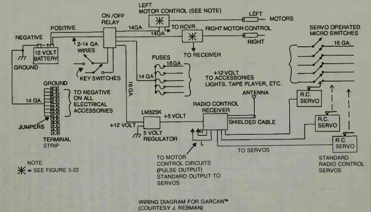
Fig. 23. The block diagram of GARCAN's control system.
Finally, on the construction side of our discussion, we note that in the following sections we will supply information about robot eyes, brains, and mechanizations, which may be of help to you in expanding on this basic unit, should you desire to do so. While it will be fun to operate the unit as is, still it is possible that you might sit back and imagine your robot doing useful tasks and jobs for you. To that end it might need arms and all the joints and appendages which will make it useful in a working capacity. Computer manufacturers have developed systems which can be interrogated and operated via telephone from anywhere. It is not beyond belief that one could have a home sentry robot in the house when one leaves home for a trip that would report by phone!