AMAZON multi-meters discounts AMAZON oscilloscope discounts
In the previous section we have discovered how a computer might be integrated into an automated control system (a robot) and we assume that the computer will take over and direct the machine. This is what we want it to do. We also have, deep in the recesses of our minds, the idea that the computer will have been programmed by us, so that the machine will do the things we want it to do. This may not be a revolutionary idea, but it will be our working principle concerning the incorporation of the computer into the system.
In this section, then, we want to try to examine some of the ways in which we program such a computer. What types of languages are used for control? How do they differ from other computer languages which we might be familiar with? We shall not restrict our examination merely to the hobby type machines but will expand our knowledge by investigating methods used in the commercial world of robotics. In a majority of cases we will find that what applies to one situation will apply to another.
As we well realize, one of the closely guarded secrets of the commercial robotics companies may well be how to communicate with a particular machine. There is a good reason for this. The simplicity or the complexity of the language governs the simplicity or complexity of the machine itself.
The software used with a commercial robot may be a vital key into its most guarded operational secrets. New patents are filed constantly. And just as there are new machines arising, there are also new methods of controlling these machines.
For a variety of reasons, some manufacturers are reluctant to reveal these methods.
A PRELIMINARY LOOK AT MACHINE COMMUNICATION
Since our communications to a robotic machine involves telling the machine to do something, we must first have in our minds the sequence of actions that we want performed. Let us use a simple definition to expand that idea of action. Let us call whatever the machine does an event. If it makes a light flash, or it causes a visual blob on a TV screen, or it makes a motor turn 1/8 of a radian, it is an event. It is the outcome of having the machine perform an instruction, which we will convey to it in some kind of language that it can understand.
So, one of the first premises that we must make is that we can take something we understand and this will-through a con version device of an electronic nature-become an electronically coded signal which the machine can understand. When we can do this, we can communicate with the machine.
Let us think of a simple example for a computer-machine system. Suppose we choose a simple lettering arrangement such as GF to mean to us that the machine must engage such mechanisms as necessary to start the machine moving in a forward direction. We must be clear in what we mean by forward in this situation. If we have a machine which is mobile (a robot such as GARCAN) this letter code would mean that the drive wheels start up and both rotate at the same speed in the same direction moving the robot in the direction it is facing. We must have agreed with ourselves that this is how we will define forward because there is no other reference used in this robot system except its own body geometry. Notice we have assumed that the robot can "face" in a direction! We derive this from the human body which has a "facing" direction and a "rear" direction! The letter symbols GF mean absolutely nothing to the machine until they are translated into its language. The machine uses electricity as a working element, and so GF must convert to electricity in some unique and distinct manner so it cannot be confuse with any other electrical signal(s) which might be present in the system. The computer can take the GF input from two keys on its keypad and from its memory section produce, as a function of time, a very specific series of pulses when each key is pressed, which, in turn, represent a code inside the machine, which can cause things to happen. As you know a pulse, is known as a "one", and the non-existence of a pulse, within a specified time interval, is known as a "zero". Each stream of pulses for each key is unique. In computer language a machine word has been formed.
Let's make the case easy by assuming that we get a code like 1111 when we depress the key with the letter G. On the way to the big event, the four ones go to certain other circuits.
The four ones energize-in this example, four gate circuits which will energize some solid-state or physical relay circuits, which could cause events to take place mechanically if and when another code signal of the machine type energizes the second input to the gate. So we now depress key F and release another string of coded signals. This time we have designed the memory bank to release a signal which looks like 0001 three zeros, or no pulses, and then a pulse, all in the proper time relationship. These signals also go to those four gate circuits. You've already guessed what happens: Three of the gates having a one from the first letter now get a zero from the second letter and so these gates do nothing! But that fourth gate gets a one from the first letter and a one from the second letter and so it activates its relay and that relay then applies electrical power to the drive motor system of the drive motors in such a way that the machine moves forward.
Now we can begin to imagine a program to cause many events to take place. Such a program would simply be a series of two letter commands, taken in proper sequence.
When we think of a program through a computer we must also consider a time factor. In the previous example, how long do we want the machine to go forward? If it is for a specific length of time, such as, for example, the time it takes the arm of an industrial robot to swing from an end position to the start position, then we must either have a clock timing the arm movement or a sensor at the end position which, when activated will send a signal the machine can understand, back to its computing section to tell it to stop sending forward signals out of its memory.
So, what's the problem? The problem is to have a computer that can convert the type commands we wish to issue into suitable control signals for the mechanism to produce events. Our commands may be of the immediate input form, such as when we type them on the keyboard, or they might be a stored typed on disc or cassette if we decide we don't want to sit there and command that unit all day! If the machine is to perform many complex movements or operations or events, then we will need subroutines performed in the proper order and sequence so that no one--not even ourselves--can get all mixed up and forget or omit some command which is necessary to the whole operation. Very, Very, careful and accurate programming, complete, and without bugs is necessary for control of machines! Figure 1 illustrates this discussion.
WHAT ABOUT THE ROBOT THAT LEARNS?
We have mentioned a type of robot machine which is taught what it must do by having it go through the series of required movements and actions under the direct control of a human teacher. One such robot is the Cincinnati Milacron T3 Industrial Robot, shown in Fig. 2 doing a commercial welding job. The robot is an articulated arm, and here it works with a robotic companion, to the left in the photo, which is a small squatty unit which turns the work to various positions as required. We know, just by looking at the photo, and with our limited knowledge of welding, that the arm must be capable of moving that welding wire and torch to just exactly the right place for a spot, or along just exactly the correct line for a seam. It must deposit just the right amount of weld material, with the proper heat, for a perfect joint. It does this under the guidance of a computer.
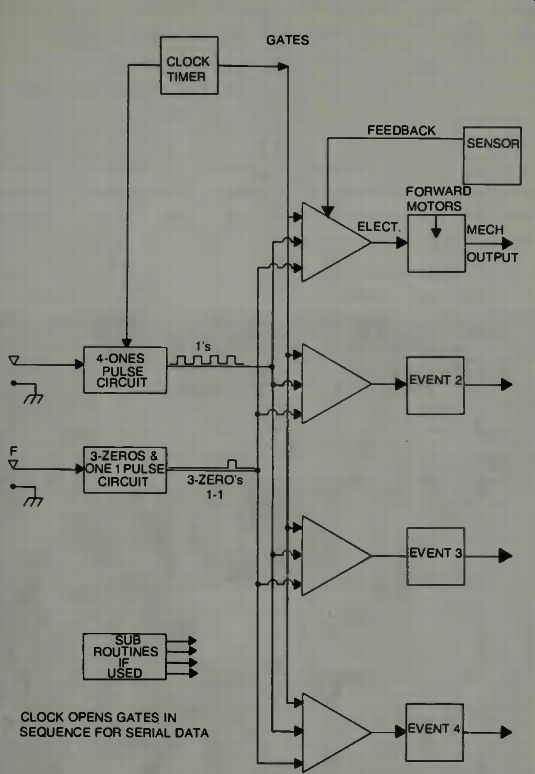
Fig. 1. An elementary concept of a computerized control system.
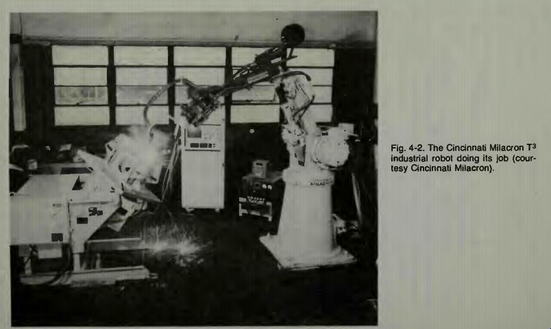
Fig. 2
Before moving further into the operation, let us examine the physical aspects of this arm in more detail. This is beneficial because this type robot is in great demand in industry, and as the demand for goods built to rigid specifications in creases,-more and more of these type robots will be found in the plants and manufacturing centers. They will do much more than just welding operations or paint spraying. These type robots, perhaps with some modifications and improvements, will be doing assembly of intricate parts, moving various batches of materials from place to place and so on.
They will in the final stages of an assembly line conduct the testing and evaluating of manufactured items and will accept or reject such items as necessary.
Examine Fig. 3, which shows the articulation of the arm, and its ancillary equipment. Notice that both electrical power units and hydraulic power units are used to obtain the necessary movements. You can see the hydraulic piston in side the elbow, for example, and you know that electric motors are used at the wrist and gripper because they furnish adequate power and are fast and small and relatively light weight. In Fig. 2, if you will refer back to it, you can see the large electric motor which is located at the shoulder position.
It is of some interest to examine more closely the wrist and gripper part of the arm as shown in Fig. 4. We see some details as to the number of motors used. Their size, and how the whole section is designed so that there can be little open space for dust and dirt to enter into the machinery is illustrated. Various types of grippers, the robotics word for fingers, can be attached to the disc.
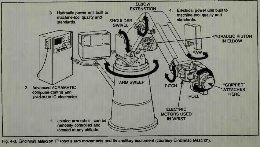
Fig. 3
Fig. 4. The wrist and gripper of the Cincinnati Milacron T 3 robot (courtesy
Cincinnati Milacron).
On the application shown, one must realize that there must be a coordination between the arm and its companion, the holding and turning unit. There is this coordination, and it comes about by means of computerized control. Thus it is incumbent upon the computer to know, exactly, where in space the gripper is at any moment, and where the position of the work is. A programmer had to figure out just how the arm should move, that is, how much of a shoulder movement, how much of an elbow movement, how much wrist movement, was necessary to get the torch to the required points in space each time a move of that torch-tip was required. As you can easily see, there are countless movements of the arm itself and all its moving parts which might be used to change the position of the torch in space. But perhaps only one set of movements will give the end product, the required movement in the shortest time and in the most efficient manner. That kind of movement must be the result of a good programmer's software development!
TEACHING THE CINCINNATI MILACRON T 3 ROBOT
No, you do not have to be a programmer in order to operate this robot. But, what you will need is a small teaching control unit such as is shown in Fig. 5. You can examine the photograph and see the types of functions controlled by this unit. Essentially it will permit the movement of the arm gripper to any desired position, and it permits a check on the programming sequence by means of a replay, so that you know if the actions you have taken the arm through are really what you wanted it to do! Also, it is possible to have some programs stored on cassette tapes so that you can use them when appropriate. Change the arm movements with another tape and then later, if it is needed, you can go back to the first tape for the original movements.
Let us suppose that the job which we want to teach the robot is simply a pick and place operation. That is, it must move to an acceptance position. When the object that it is to move comes along it will grasp the object, lift it and move it around to another belt and then set it down, gently, and carefully, and then return to the acceptance position to wait for another object to come along. In this very simple example, we aren't worrying about how the robot identifies the objects, or if it is only to pick up certain objects from among many that might be on the belt. We are just assuming that at very precisely controlled intervals, along comes this thing which the grippers on the arm are positioned to intercept. We aren't even worried about the position of the thing. We assume it will be so positioned that the grippers will be able to engage it tightly in a proper manner and lift it without damage or slippage.
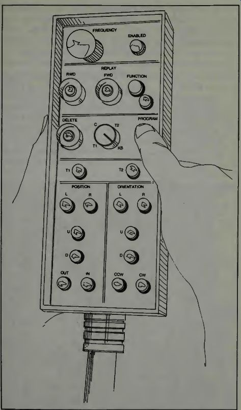
Fig. 5. The teaching unit for the Cincinnati Milacron T 3 robot arm. Step-by-step
movements are stored in the robot's minicomputer; the computer simplifies these
directions and controls the arm movements.
Let us examine the teaching unit of Fig. 5. Notice that we have some buttons which we can depress which will move the arm, the wrist, and the grippers, in a multitude of directions. At first we proceed slowly trying to make the arm swing around and set its gripper down on the belt in the proper position to intercept the thing. If we make mistakes, we can delete them and try again. Now we want to make the arm remember this segment of operation and so, through the proper button on the teaching device, we enable the computer to memorize those movements we have had the arm perform.
We want to be sure. So we manually bring the arm around to some arbitrary position and we engage the section which causes a replay of our operation. The arm should move around to the desired position and open its grippers ready for the thing when it arrives. But, notice! The arm did not necessarily move in exactly the same manner we moved it! Now what? Is the arm beginning to think for itself? No, the computer has taken all our little pieces of movement and examined them and then, using the software de-signed by some expert programmer, has done some re calculation and determined that the way we moved the arm isn't the best way to move it. So the computer works out a new spatial trajectory and moves the arm in its own manner.
The arm moves to exactly the position we want it to move to.
It orients itself in exactly the manner that we had it orient itself and the only difference is the way the arm moves in space to get there.
Now we need a thing and we need to slowly steer the arm so it picks up the item and moves it over to the new location and sets it down carefully on the belt and releases it. We take the arm through those movements, using the button controller. We then check our operation by a quick replay and if all is all right we commit that section of movement and operation to the computer memory. Finally we cause the arm to return to a starting position where it will lie in wait for the next thing to come down the input belt into its hungry jaws! Because we don't want to make this seem too simple- although the teaching operation is relatively quite simple- we present the following description of motion as stated by the manufacturer: "During the teaching, the operator has available three different spatially coordinated motion systems; that is, paths along which he (or she) can move the arm from point to point.
"Cylindrically coordinated motion moves the arm around the vertical axis of the robot and in-or-out from that axis.
"Rectilinearly coordinated motion moves the arm along (x,y, and/or z) coordinate lines.
Wand-coordinated motion moves the arm through as many as all three of the T3's available axes (x, y, z, or roll, pitch, and yaw) simultaneously. Because all axes are coordinated, the arm moves only in a straight line from point to point and maintains orientation even though all three axes are in mo tion. Hand coordinated movements of the robot arm can be compared best to the movement of the human hand which goes from place to place in the I shortest straight line path without any regard to any other spatial orientation of the body.
"All three of these motion systems are selected by pushbutton on the program entry terminal (teaching unit)."
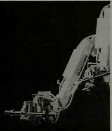
Fig. 6. The robot arm selects a thing' and picks it up and moves it (courtesy
Cincinnati Milacron).
DOING OTHER JOBS WITH THE CINCINNATI MILACRON T3 ROBOT
The reason that this arm can do other things is that it can be equipped with sensors, and the arm is programmed from a computer directed base. This means, that like all computerized activities, software has been developed which makes it possible for the robot arm to understand human commands. Let's examine what the robot can do in a materials handling role. Figure 6 shows the arm stretched out at a low level to enable its grippers to grasp a thing. Next we can see how the arm contracts as it moves upward.
Note in the lower right corner the display unit of the computer cabinet. It is possible to look at the computerized program for this robot on that display screen, and programmers will be happy to know they can delete or add or even build a program using this display unit without having to actually move the arm at all. It might be somewhat similar to writing a program at home on your home computer. This screen also will display diagnostic information, should that be needed.
Finally, we mention that the reference point in this system is that spatial point where the gripper tool meets the workpiece. You have to know where that is, visually, if you program with the little control box, but not necessarily mathematically. The computer will mathematically find out and determine the space coordinates of that end point.
SUBROUTINE PROGRAMMING FOR A ROBOT
A subroutine for any computer generally means some pre-defined action which will be called at some point when an appropriate command or signal appears in the general pro gram. In a way it is an aside action, and the overall operation of the computer is stopped while this side action is in effect.
When it has been completed, the computer will then pick up where it left off in the main program and, possibly using the information from the side action, continue on its main pro gram operation.
With a computer which controls a robot machine, the subroutine is sometimes called a branch action routine. This simply means that the movement of the robot arm will be made to follow something other than its normal movements when an appropriate activation signal causes it to go into the subroutine programming. We need to examine a situation which illustrates this.
A truly general-purpose industrial robot system must have some way of selecting or altering the normally programmed path and functions of its arm based on changes in the working environment in which it operates. The name given to this ability may vary from manufacturer to manufacturer, but the purpose of the operation will always be the same. When the robot's moving part reaches some point it will pause to see if there is another signal at that point. If that signal exists, then the robot will move into a subroutine. If, when the robot looks for that subroutine input signal, it finds that it does not exist, then the robot will continue its normal operations in normal sequence.
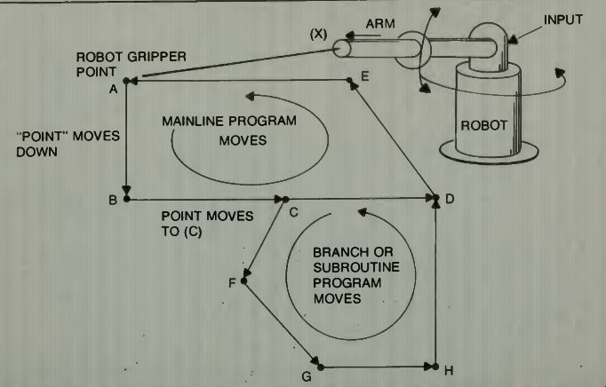
Fig. 7. A subroutine-controlled arm movement of a robot.
In Fig. 7 we see a diagram which shows a mainline program movement of a robot's arm, and a branch or sub routine break in that normal program movement. The exit into the subroutine movements occurs at C when an appropriate signal comes into the robot's input. Normally the arm will move on the trajectory A, B, C, D, E, and back to A. We can also assume that when the arm is not working it will be retracted to the position X, and that it must first extend from X to A before it goes around that mainline trajectory. We will imagine that the arm picks up something at A and moves it around to E, drops or positions it there, and then comes back to A to get another part.
Now let us see what could happen if an input signal comes at the proper time when the arm pauses at C. Suppose, just for an example, that the part picked up at A may need to have something else attached to it at F, G, and H before it is ready to be placed or positioned at E. The branching input signal then could mean that this part needs to go to all the stations. The main program trajectory line is changed to accommodate this required action. The arm goes into a branch trajectory or into a subroutine program at point C and exits that subroutine at D whence it is back on the mainline pro gram trajectory once more. Notice that if the arm pauses at (C), and no input signal arrives, the arm will move on from C to D and will not go through the subroutine operation. It is important to realize that this is not a real-life example, but just a discussion and illustration to show what a branch pro gram or a subroutine program is.
In practice there usually is a large number of these subroutine programs in operation. For example, if during inspection of a machined part some defect were found, the robot might branch to another part of the program that would dispose of that defective part, alert an operator to the fact that a defective part was there, and then the robot might just shut down operations (as specified by the subroutine) until the part was repaired or replaced or whatever.
The method discussed called standard branching is the simplest way to change the robot's path programming, but these standard branches are limited because each branch must be associated with one particular input signal to the robot's control system. This means that if there are X signals required there should be X lines to carry this information to the control system. It is possible to have fewer lines if an external decision-making element (a computer) is available which can look at all input signals simultaneously before specifying the branching or subroutine operations. With 8 lines there are 28 or 256 different conditions for branching that can be identified by the computer. In the Milacron Robot System the extension of the standard branch is called a conditional branch or subroutine.
THE COMPUTER OUTPUT FOR A CONDITIONAL-BRANCH SUBROUTINE
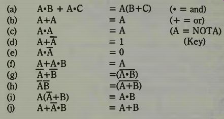
Let us see now what kind of computer output could result from having the computer look at all 8 input lines and the 256 possible conditions for branching. We are agreed, now, that the computer will look at all these possible inputs and will activate a subroutine or branch program if, and only if, the voltages present on the 8 lines represent a certain signal. For example, if the arm were programmed to branch into a sub routine at point B of Fig. 7, but the computer was told, "Branch B 1,-5,7,-8," then that subroutine would be entered into if, and only if, signal input 1 is on, and input signal 5 is off, and input signal7 is on, and input signal 8 is off! If the computer looked at these particular signal inputs and found any of them different from the specification, then it would not command the subroutine branching at B and the arm would continue on its normal trajectory to C. Notice that it is possible to express the robot's operation completely in Boolean Algebraic expressions.
=======
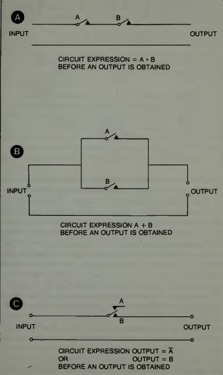
Fig. 8. Some Boolean algebra expressions illustrated.
========
BRIEF BOOLEAN ALGEBRA REFRESHER
Boolean Algebra is called the algebra or logic. It was invented by George Boole, mathematician and logistician, in 1847. This is the algebra of automatic control and switching devices in today's world. It permits one to present switching circuits with algebraic symbols and then to manipulate those symbols according to the laws of algebra so that one can find the simplest manner in which to accomplish complex switching and operation of various electronics and electrical circuits.
Boolean Algebra deals with truths and non-truths that relate well to switching devices that are either on or off.
Digital devices use "states" to represent one or zero which is roughly equivalent to a switch being on or off. Therefore, Boolean Algebra is well suited for digital work. Let us apply this concept to a simple circuit.
Let us say we have a circuit with a switch and a light in it.
We can say several things about that circuit: (A) The circuit is on (B) The light is on Algebraically we can use the letter symbols of these statements to indicate and express the condition of the circuit and the light. For example:
1. A.B (meaning A times B) means that the circuit is on AND the light is on.
2. A+B meaning either the circuit is on OR the light is on.
Finally we can write:
3. Ajl- 3 - where the bar over the B means NOT or a negative. Thus, the circuit is on and NOT the light.
These are the three basic functions of Boolean algebra, they are the AND, the OR, and the NOT functions.
When this kind of algebra is applied to circuitry, it is common to use the multiplication function for series connections, see Fig. 8A. For parallel connections one would use addition (Fig. 8B), and a negative situation is at Fig. 8C. It is common to use a zero for an open circuit output and a one for a closed circuit condition.
With this concept of algebraically stating the condition of circuits, it is customary to express the Boolean conditions as follows:
-------
LAWS OF BOOLEAN ALGEBRA
Note that the dot is sometimes dropped, just as in algebra, and order is from left to right, unless specified by parentheses.
It is common to take a circuit and develop a Truth Table of its operations. This is a chart in which all the outputs for all the conditions of the switches are stated, one at a time. Then letters are assigned to the switches, and, as you have seen, the expressions of the truth table lines can then be put into Boolean algebraic expressions which can be reduced to the simplest expression. By re-converting the letters back to switches or switching circuits, a person is then able to draw the best circuit, and the simplest circuit, for that device.
One can quickly see how such a mathematical tool can be of tremendous value in the field of advanced robotics. As we have indicated in the Milacron robot, there might be many inputs to the machine under various conditions of operation.
There will have to be conditions of multiple switching inside the robot's mechanism to make it do what the inputs call for.
Being able to mathematically state the operation using Boolean algebra helps to arrive at a cost-effective unit which will do its job in the prescribed manner.
MORE ABOUT ROBOT BRANCHING OPERATIONS
To illustrate one use of conditional branches, imagine that you have a material handling situation in which a supervisory computer is being used, and this computer is also being used for other automation functions. Remember that the number of lines required for a given robot's operation can be stated in powers of 2, then, if the robot machine requires 16 signal inputs, the robot will require only four lines to convey to it all the information it needs to get the proper branch program into operation.
In many applications of a robot machine in industry it is desirable for the robot to have a method for creating a branch operation that can be used at a number of points in the robot cycle; a branch that can effect its movement sequence, regardless of the physical location of the robot arm, when the branch operation is requested. For example, when the branch operation affects the robot's gripper position and/or its wrist orientation.
Some kinds of applications require another kind of offset branch, where the branch can be entered, not only at specifically programmed points, but anywhere or anytime in the normal cycle of operation. When a proper input signal is received by the arm-control unit the signal can cause the robot to enter into an interrupt offset branch operation. One example is that illustrated in Fig. 9. In this illustration one can see that the arm is caused to move on trajectory OB01 OB02 when the interrupt signal is received at point X on the normal trajectory from M005 to M001. Notice also that at each position M002 and M003 and M005, the robot's arm will go into the type of branching operation specified by the OA numbers. Notice that the type of movement for each of the M points is exactly the same when the branching occurs in the OA series, as shown in this illustration. So the same sub routine called for at point M002, can be called for at M003 and M005.
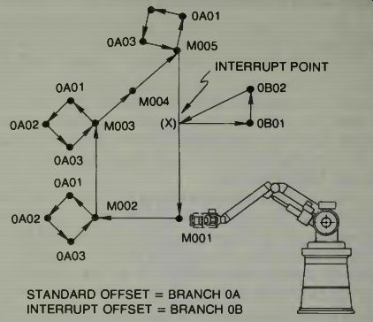
Fig. 9. Offset branching of a robot arm (courtesy Cincinnati Milacron).
The question as to what an interrupt branching operation might consist of may be answered by considering that it could be a twisting, jerking, series of movements of the robot's arm which would cause a welding gun tip to be loosened from a stuck position on the work piece. A sensor of some type would have to monitor the gripper movement, and in event it becomes stuck or does not move along smoothly as it should, then this sensor generates the signal which causes a special routine to be implemented immediately by the computer.
That, of course, in turn, activates the arm into the special motions described.
Extending this concept one can realize that special routines might be required for many applications. If the robot's arm handled the moving of objects which normally are spaced a given distance apart, and timed precisely on arrival at a given position, then if something disturbs the flow, a sensor would generate, perhaps, a wait or delay signal to the arm.
THE ROBOT'S SEARCHING FUNCTION
In addition to altering its cycle by entering branches, a robot system such as the Milacron can adjust the position of data points within an existing cycle, based on changes in external equipment and workpieces. In a way, this might be called adaptive control where the current condition of some thing specifies what the future operation will be.
One example of how this type of adaptive control might be used is in stacking, or handling operations from a stack, where the items may have a variable thickness, or the stack may vary in thickness or height. In this case you can readily realize that the arm must progress from some fixed-level starting point, where it begins to "pick up" the parts, and descend to lower and lower levels each time a part or work piece is moved out of the stack. The control operation in this type of movement is called a search function.
The data comprising a complete branch sequence in the robot control can be rewritten with data from the external computer system. Thus, if the position or orientation of a workpiece varies, the robot's movements and functions can be adjusted by the external device so that it will properly pick up or perform the required operations on the workpiece. If an emergency situation is detected, a branch can be replaced with other branch data which will enable the machine to handle this specific emergency condition. The speed at which this data can be transmitted to the robot control is fast enough to complete the communication in a fraction of a second, so this type of branching has been and is called adaptive branching.
MORE ON THE SEARCH FUNCTION
The search option on Cincinnati Milacron's robot can be used in stacking or un-stacking applications. In teaching the robot the task, two points, one above the stack and one at the bottom, are programmed. Then a tactile sensor on the robot's hand is used to send an interrupt signal to the robot control system whenever the hand encounters an object in its path, as it moves between the two programmed points. The interrupt signal causes arm motion to cease immediately. Then the function associated with the subroutine is executed. The arm then proceeds to the next point in the main program which may be back to the original starting point.
In an example, imagine that the robot arm is to pick up some automobile windshields from a stack of them, and place them one at a time on a conveyor belt, off to one side of the stack. Recall that only the starting point above the stack and the bottom point, at the bottom of the stack, are necessary to be known by the robot's control machine. Thus, when the arm goes from the start position down the stack, it stops itself when its sensor contacts a windshield. The gripper then grips that unit, and immediately moves it along a prescribed path to the conveyor belt and deposits it there. Then the arm goes back to the start position and resumes the operation all over again. It is not necessary for the program to include the specific pieces of work on their positions, the sensor on the robot's arm takes care of that. Only when the robot's arm reaches the second point, or stop position-meaning it is at the bottom of the stack-will the arm move to some rest position and stop moving.
Of course we realize the possibility of interrupting a normal branching operation with an interrupt signal. This signal might cause the arm to skip some movements and move on to others, or go into an entirely new routine. Of course any routine must have been taught to the computer by moving the arm, with the teaching unit, or must be specified by signals on a cassette or other similar type tape.
COMPUTER-USE SUMMARY
So we have learned that a computer can direct a robot-which, of course you already knew-and we now have some concept of how the computer does this. The output of the computer will be a series of signals to a bus which might have, in our case, say, eight lines or terminals. When various keys are pressed on the computer keyboard, the closing of the key-switch contact will cause the computer, through its internal circuitry, to energize some combinations of these terminals. Since a terminal status can be specified by being either on or off-a two state condition-we can then consider the permutations and combinations of eight things taken in two conditions and we find that there are 256 possible states of output, each being completely different. Of course if we go to a 16 line or terminal type output on the I/O board, then we will have 2 16 unique states for control. We leave it to you to determine the numerical value of this possibility.
In order to control the higher values of voltage and current necessary to really operate the control system of a robot, some isolation condition must exist between the computer and the controlled circuitry. This can be accomplished by using optoelectronic circuits, or reed relays, or some kind of similar devices. The computer output then operates these devices and they, in turn, will operate the higher current and voltage control lines.
When sensor input is required to the computer, these signals come from sensors attached to the robot's positioning and moving elements or from scanning elements such as TV microwave, sonic, or thresh-hold switches. Sensors such as piezo crystals generate a current proportional to the force on their containment cases. This voltage then must be digitized as it originates in an analog form from the sensor. In other words, it exists as a continuous level of current or voltage and it must go to some circuit which will convert it into a computer word. As a very simple example suppose that the amount level of the sample is one volt, then the word might be 00000001 for an eight bit word. If the voltage level is two volts, the word might be 00000011 and so on. In any event a particular series of off-on pulses or bits will now represent the sensor level signal to the computer.
The computer can work with this. It routes the pulses to various addresses which in turn release new signals to the I/O board which then passes them on to the control circuitry for the robot's moving elements. Notice how the computer might get a particular feedback signal from a sensor, and when this signal goes to the memory banks it might cause a sub routine program to be initiated. The subroutine will be unique and special and non-duplicable by any other input signal. So, anytime it is necessary for the robot to move in accord with this particular subroutine program, that particular signal of ones and zeros must be received by the computer.
SOME CONSIDERATIONS OF ROBOT DESIGN
The robot is a machine and can be a very complex machine if the situation and conditions warrant this type of development. The robot falls into a category of machines which are usually studied under the heading of feedback servomechanisms. This is really a fascinating subject and it embodies the best application of such mathematical concepts as the LaPlace Transforms and Fourier Transforms to express mathematically how such machines will operate and react to various input or operating conditions. When designing such a robotics system one takes into account such things as:
The system environment
Noise
Nonlinearities which can exist in the system
Component limitations
Undesired disturbances
Size and weight and space and power requirements
The random inputs which may occur.
If you get into the design of such devices, then you should be familiar with such mathematical techniques as the Maximum Principle of Pontryagin, Bellman's Principle of Optimization, and Wiener's Least Squares Optimization. Some suggest that classical calculus variations of these should be understood.
These mathematics enable a person or designer to put down on paper the design of a system and the analyze its operation before building it. Thus when it is built, it can be expected to operate in a given manner and within a given type of specification range. Computers enable one to solve the most complex of problems easily, so all one has to know is what mathematics to use and how to set up the problem for computer solution and what the computer solution actually means! We have mentioned adaptive control in connection with a robotics system. It might be important to examine this concept just a bit more in detail. Adaptive control means, simply, that the machine will adapt its operation to a change in either its external or internal environment. A self adaptive control system is one which has the ability to change its operations through a process of measurement and evaluation and adjust itself to a new set of conditions in which it operates.
What a robot design engineer is always looking for is the optimum response or operation of the system. That is, the system must not work too fast or too slowly, but at the right speed for the process or job at hand. If there is some change in its environment-say that this might be the speed at which parts are sent to it-then it should be able to adapt itself to the new speed of arrival of parts and continue on merrily and happily without any problems.
To make a system which does things at the right speed, as an example, we make an assumption that we know what the right speed is. We then program this speed into the machine and provide it with sensors which can determine at what speed it is operating. Then, inside the machine, some computing element compares its speed at present to the speed which we say is ideal, and the machine can then take the difference between these two and uses that as a control signal to adjust the speed of operation. Of course, you might imagine that the speed signal we send into the machine when the operation starts is just a priming signal. Once the mechanism is in operation, this signal is constantly adjusted by adaptive circuitry so that the optimum or best response for that situation is accomplished.
In the advanced world of robotics design you make use of sampled data systems as well as adaptive control systems.
SOME CONSIDERATIONS IN PROGRAMMING A MOBILE ROBOT
It will be beneficial to consider some aspects of programming a robot that can move about. We know that if a sensor senses something which might call for some movement of the robot, what that sensor really does is to cause a signal to be generated which then calls a subroutine that causes the necessary electrical power to be applied in such a way that the movements are accomplished. Let us consider how we might program a robot to move in a given way in a given area.
As a first consideration we are faced with the basic question, "Where is the robot? What are the robot's X and Y coordinates at any second? What reference plane are those coordinates on? Luckily for us, some manufacturers have developed what is called a stepping motor. It can help us answer the basic question.
As you know a stepping motor is one which revolves a given amount when supplied with a pulse of electric current.
That amount might be five degrees or it might be twenty five degrees. If pulses are supplied in a continuous train, the armature of such a motor revolves in a continuous manner, and if the pulse rate is fast enough we will not be aware that there is any difference between the rotation of this type motor's armature and the armature of any other motor. Both revolve smoothly and quickly, but, there is a difference, and an important one to us.
With a stepping motor we can govern distance traveled or arm movement quite precisely. If we have a motor which turns five degrees with each applied pulse, due to the way it is built there must be a space (no-pulse) following each pulse, or it won't work right. Divide 5 degrees into 360 to get the portion of a turn each pulse represents. This number times the circumference of the motor wheel is how far that wheel will move on a floor with each pulse. Next we make a small diagram of the movement our mobile robot should follow as shown in Fig. 10.
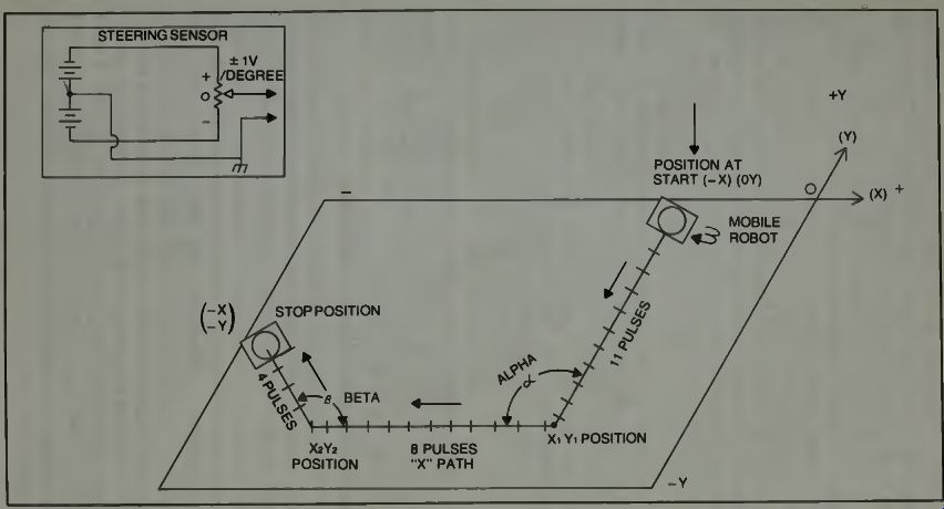
Fig. 10. Map of pulse drive wheel controlled by a subroutine.
What we do is to program a number into the computer memory, for this example the number 11. Next we program the computer so that when this number has been counted down a subroutine will activate which will cause the steering wheels to turn as shown through the angle alpha. The computer knows that this has been done by monitoring a voltage proportional to the angle the steering-drive wheels make with the robot's frame, which can come from a potentiometer mounted on the steering section of the robot. Now a second drive subroutine count-down section begins and at the same time the steering wheels will equalize in speed turning straight ahead almost immediately after the robot starts moving. It will move straight along the X path for 8 pulses, turn again thru the pre-set angle and continue 4 pulses to the stop position. If you try to make such a robot, some experimentation will be required, but this concept will enable it to do what you want it to, if you program the pulse count-down correctly, and make the turn-angle sensor equipment properly.
This is just an example. There are other alternatives.
One alternative would be to put a small magnet on the face of a drive wheel which is driven by a regular electric motor. Each time the drive wheel makes one revolution a pulse is generated which can be used to make a computer circuit count down. Or if a more precise robot position location is needed, then two such magnets, moving by a fixed coil spaced 180 degrees apart will give two pulses per wheel rotation.
One might use the wheel pulses by sending them to a circuit which will accumulate them into a voltage and when this voltage is high enough, it can trigger a relay or some such device which will cause other circuits to energize. Now that you have the idea, you can build on this concept to achieve something satisfactory to your own needs and capabilities. It is a fun project and when you can make your robot move around a room without hitting anything, or stopping, or get ting off track, then you will really have done something! In the industrial sense, the previous example shows how a robot's arm might be programmed during a cycle. Then if the program is repeated over and over, the cycle will be repeated as long as the program is run.
COMPUTER LANGUAGES FOR ROBOTICS
There are no fully defined, recognized languages for robot control. Individual manufacturers tend to put together whole systems, including CPU, and define each movement in a subroutine that the user calls by typing in a short code word.
These subroutines are, of course, in machine language, and the programmer at the factory that made the robot had to use machine language because it is the only language that allows the level of intimacy with the internal workings of a given CPU necessary for programmed control. Limiting the user to those routines that the original programmer foresaw a need for is not the best use of the system's capability. Allowing complete programmability appeared preferable, but there are problems here too.
First, many programmers lack the combined hardware and software knowledge needed to do control programming.
Second, the company is understandably concerned about disseminating too much information dealing with the internal control of a machine that they have invested years of design work and money in. Third, most companies installing such a system would probably not want to hire a programmer just to do one job (though this is changing) and a short term contract with a specialist is pretty expensive. There is a solution though, and most companies will probably be going to this method eventually, though today most are still using the first method discussed.
There are high-level languages that are very easy to program in but do not compile down to very efficient machine code. Most of them have the capability of linking subroutines that are already in machine language to a program being compiled. So the manufacturer writes a group of very efficient routines for directly controlling the robot, and supplies them as a library of added functions to a language like BASIC or FORTRAN. There have been some studies of robotics conducted at Stanford Research Institute in which FORTRAN has been used. In one such study a mobile robot was programmed to move about a floor space and was asked to move certain objects, by pushing them, into various positions in that space.
This study was conducted for the Advanced Projects Agency of the Rome Development Center, Griffith Airforce Base, New York. It is interesting to examine a portion of their report.
"The robot system is capable of executing a number of functions that vary in complexity from the simple ability to turn the drive wheels a certain number of steps, to the ability to collect a number of boxes by pushing them to a common area of the room.
"Of the functions mentioned the simplest are certain primitive assembly language routines for moving the wheels and tilting the head (TV), reading a TV picture and so on.
"Two examples are MOVE and TURN. MOVE causes the robot to move in a straight line by turning both wheels in unison, and TURN causes the robot to rotate about its center by turning the drive wheels in opposite directions. The arguments of MOVE and TURN are the number of steps that the drive wheels are to turn (each step resulting in a robot motion of 1/32nd inch) and status arguments which allow inquiries to be made about whether the function has been completed or not.
"Once begun, the execution of any function either proceeds until it is completed in its normal manner, or until it is halted by one of a number of abnormal circumstances such as the robot bumping into unexpected objects, overload conditions, resources exhaustion, and so on. Under normal operation if the execution of the MOVE command results in a bump, motion is stopped automatically by a special mechanism on the vehicle.
This mechanism can be overridden by a special instruction from the computer, however, to enable the robot to push objects.
"The problem solving systems for MOVE and TURN are trivial. They need only to calculate what signals shall be sent to registers associated with the motors in order to complete the desired number of steps.
"At a level just above MOVE and TURN is a function whose execution causes the vehicle to travel to a point specified by a pair of X,Y coordinates. This function is implemented in the FORTRAN routine called LEG. The model used by LEG contains information about the robot's present X,Y location and heading, relative to a given coordinate system, and information about how far the robot travels for each step applied to the stepping motors." "Ascending one more level in the system we find a group of FORTRAN two-letter routines whose execution can be initiated from the control machine keyboard.
The action unit system now ceases to be strictly hierarchical (arranged in a graded series or sequence) since, now, some of the two letter commands can cause other commands to be executed. This means a branching type subroutine operation.
"In this system, developed and studied at SRI, one two-letter command (EX) takes as an argument a series of X,Y coordinate positions in the robot's world. Execution of EX causes the robot to travel from its present position directly to the first point in the sequence, thence, directly to the second point in the sequence, etc., until the robot reaches its final destination as programmed. Another two-letter command (PI) causes a picture to be read after a TV camera is aimed at a specific point on the floor to see if there is an object there or not. The ability to travel by the shortest route to a specified goal position along a path calculated to avoid obstacles, is programmed by the two-letter command TE. Execution of this command requires that the computer solve the path coordinates using a special problem solving system which is activated by the two letter command PL."
"As SRI ascended to higher functions of operation, the required problem solving process had to be more powerful and general. They wanted this robot to be able to perform tasks which, quite possibly, would require complex, logical deductions. What was needed then for this type of problem solving was a general language in which problems could be stated, and a powerful search strategy with which to find solutions to these problems.
They chose the language of first order predicate calculus to state the problems to the robot. The problems were then solved by an adaptation of a question answering system based on resolution theorem-proving methods.
One example of such a problem for the robot to consider, stated in plain English is, "There exists a situation s and a place p such that three objects called OB1, OB2 and OB3 are all at place p in situation s."
Now the problem as the robot sees this is that the three objects may not all be at place p, nor are they in situation s. So the robot must move them until this problem statement is satisfied. Notice that the command is not given to the robot to find OB1 and push it to place s, find OB2 and push it to place s, and find OB3 and push it to place s 2. In this case one would suspect that the robot would move its camera eyes around until it could identify OB1 either by color or shape or both, and then track it down and move it to place s where s has been indicated to the computer in the form of X,Y coordinates. The proof of the action would be that the robot, from a position x ry, would look at the space s and if it there found the form of OB1, it would then look around for OB2, etc.
We have included this information on this study because it indicates some methods of programming robots, and the use of a two-letter FORTRAN language. In this study, the SRI group also used LISP language. It is stated that "... Another LISP program enables commands stated in simple English to be executed. It also accepts simple English statements about the environment and translates them into predicate calculus statements to be stored as axioms. The English processing by this pro gram is based on work by L.S. Coles: "An On-Line Question-Answering System with Natural Language and Pictorial Input". (Proceedings 1968 Conference of ACM, Las Vegas, Nevada, August, 1968.) In a survey of the languages which have been used in robotics control in the past, and in work on artificial intelligence, we find such descriptive names as PLANNER, CONNIVER, SAIL, STRIPS and QA4.
THE MULTIARMED INDUSTRIAL ROBOT
If we consider the manner in which a Homo sapien accomplishes a given physical task, such as the assembly of one part to another using a bolt, a nut, and perhaps some washers, we find that not only are two hands and fingers used, but also, in some cases the fore-arms and even an immobile device such as a vice, which holds the work to which the piece is to be bolted. In a manner of viewing this situation one can say that the human has provided himself with another hand or two in order to hold everything together so that the bolting process can be accomplished. In the simplest sense, the two parts are held by a vice, one hand inserts and manipulates the bolt, and the other hand holds and/or manipulates the nut onto the bolt, after first placing the washers in position.
From this example then, we should be aware that a system of assembly in an industrial situation might involve a robot machine with three or four arms. Actually the device which positions the workpiece can also be called a part-even if it is a remote part-of that particular robot system, and so we now have to consider that a robot may not be an integrated entity all in one frame or piece, but may consist of many parts which are tied together by means of command system. In the operation of such a unit, coordination among the various pieces is affected by a computer which may have as an input, the outputs of many smaller computers, and its output may become the input for the smaller computers, thus effecting the control and timing of all elements of the system.
It seems that we might be approaching the concept of HAL in the story 2001-A Space Odyssey. The series of computers form the nerve networks and sub-brains associated with a complete automated plant's operation. This can be especially true if we consider that everything done in a given plant is to produce a product at the output, and there must be coordination and timing and productivity of the various parts as well as assembly stages and testing stages in order to finally send the finished product off the assembly line at the plant's output. Under this concept we do not have a series of robots here and there, but in effect, a gigantic robot with all the complexity needed to start with raw materials, and pro duce finished products on a constant 24 hour operation basis.
Even suppliers, distributors, wholesalers, and retail outlets might provide demand inputs to the controlling computer.
The concept becomes mind-boggling!
TESTS, ADJUSTMENTS AND REPAIRS
Even now we have computers with diagnostic programs.
One can envision in the robotics systems of the future that the machine itself, when it gets a signal from some source that something is not going exactly right, will stop, initiate its own diagnostics program to find out what is wrong, and then, using visual and audible communications, tell its human supervisor verbally to fix the bolt on number 4, left hand, third finger digit. In all the current studies, at least to date, one doesn't find robots capable of repairing themselves without human help.
Also, these robotics systems must have diagnostics programs written, and fed to it by human hands or voices. The need for people in such systems is still current and in evidence. A diagnostic program is really just a check-through of the operation to see if all the movements and operations required are accomplished with the normal input signals. If, at any stage, the robot's response is not correct, then a signal will inform the supervisor that some adjustment, testing, or repairs are needed.