AMAZON multi-meters discounts AMAZON oscilloscope discounts
Described briefly in Section 2, the term alternating current (abbreviated AC) refers to current flow that periodically changes direction. This condition is related to the periodic changes in the polarity of the applied voltage.
Alternating voltage and current are very important because of a phenomenon known as transformer action. Transformer action enables the efficient transmission of large quantities of power over long distances. This is why all common household current is AC.
AC Waveshapes
AC voltages and currents can be thought of as having waveshapes. Wave shapes are the visual, or graphical, representations of AC voltage or current amplitudes (or levels) relating to time. Common household AC has a type of waveshape called sinusoidal (sine wave for short). An illustration of a sine wave is shown in Fig. 1. Note that it is similar to a circle that is split in half, and joined together at opposite ends on the zero reference line. The sine wave is the most common type of AC waveshape you will be working with in the electrical and electronics fields.
Any repetitive, cyclic condition can be represented in the same manner as the illustration of the sine wave in Fig. 1. On the horizontal plane (that is, reading from left to right), a certain period of time is rep resented. On the vertical plane (from top to bottom), levels or amplitudes are indicated. The amplitudes above the zero reference usually denote positive variations, and the amplitudes below are usually negative. A cycle is defined as one complete periodic variation. In other words, if the illustration in Fig. 1 were to be carried out any further, it would begin to repeat itself. A half-cycle is either the positive half, or the negative half of a full cycle. Notice how the positive half-cycle would be identical to the negative half-cycle if it were to be turned upside down.
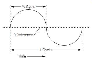
FIG. 1 One cycle of a sinusoidal (sine) AC waveshape.
AC Frequency
The speed or rate at which an AC voltage or current waveform repeats itself is called its frequency. Frequency is measured in units called hertz, which is a method of relating frequency to time. One hertz is one cycle of AC occurring in a one-second time period.
If you have never been exposed to the concept of AC waveforms, this all might be rather abstract to you. To aid in understanding Fig. 1, assume it to be one cycle of common household AC power. Common household AC is usually labeled 120 volts AC, 60 hertz (or "120 Vac, 60 Hz"). This means that the usable amplitude of the power is 120 volts, and it cycles at a rate of 60 times a second. If Fig. 1 represented this type of power, the time period from the beginning to the ending of one complete cycle would be about 16.6 milliseconds (ms). The time period of a half-cycle would be about one-half of the time period for a full cycle, or about 8.3 milliseconds.
There is an inversely proportional (opposite) relationship between frequency and the time period of one cycle. In other words, as frequency increases, the time period per cycle decreases, and vice versa. Equations ( 1) and ( 2) show how time is calculated from frequency, and frequency from time:
Time period _ ( 1)
Frequency _ ( 2)
For example, to convert the common 60-Hz power frequency to its associated time period, you would use Eq. ( 1):
Time period ___ 0.0166 second 1
_ 60 Hz 1
__ frequency
The time value 0.0166 second is commonly referred to as 16.6 milliseconds. If you knew the time period of one cycle, and wanted to calculate the frequency, you would use Eq. ( 2):
Frequency ___ 60 hertz 1
_ 0.0166 1
__ time period
NOTE: Whenever a number is divided into 1, the result is called the reciprocal of that number. Therefore, it is proper to state the time period as being the reciprocal of frequency. Likewise, frequency is the reciprocal of the time period.
AC Amplitude
As stated previously, one-half of a complete cycle is appropriately called a half-cycle. As shown in Fig. 1, for each half-cycle, the voltage or current actually passes through zero. In fact, it must pass through zero to change polarity or direction, respectively. If Fig. 1 is a voltage wave form, the voltage is shown to be positive during the first half-cycle, and negative during the second half-cycle.
The horizontal dotted line representing zero is called the zero reference line. As shown in Fig. 2, the maximum amplitude of either the positive, or negative, half-cycle (as measured from the zero reference line) is called the peak voltage. The total deviation from the negative peak to the positive peak is called the peak-to-peak voltage.
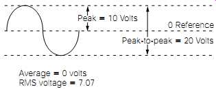
FIG. 2 Relationship of peak, peak-to-peak, aver age, and rms voltages
relative to a sinusoidal waveshape.
Defining the amplitude of pure DC voltages and currents is easy, because the level is constant and continuous. Defining AC voltage or current amplitudes is a little more complicated. As shown in Fig. 2, the peak voltage of this waveform is 10 volts. This represents an instantaneous voltage level. At other points in the waveform, the voltage level is less than 10 volts (sometimes even zero), and it can be of positive or negative polarity. For this reason, there are numerous ways to accurately define alternating voltage and current amplitudes, depending on the application.
One, somewhat controversial, method of defining an AC amplitude is by algebraically adding the negative half-cycle to the positive half-cycle. Because the positive half-cycle of a true sine wave is the "exact opposite and equal" of the negative half-cycle, the two cancel each other out, resulting in an average of zero. If this is difficult to understand, consider this analogy. A DC voltage or current is like driving a car in one direction. The passengers in this car will go somewhere, and end up in a different location than where they started. In contrast, an AC voltage or current is like driving a car back and forth in a driveway. The passengers in this car can ride all day long, and still end up where they started.
This is why a DC voltmeter (a test instrument for measuring DC voltage levels) will measure 0 volts if a pure 60-hertz AC voltage is applied to the test probes. The DC voltmeter cannot respond to the rapid AC polarity reversals. Therefore, it indicates the average level, or zero. In the beginning of this paragraph, I stated that this is a controversial definition.
In many electronics textbooks, the average AC amplitude for a sine wave is defined as 63.7% of the peak amplitude. Technically speaking, this is incorrect; but it was generally adopted because many older type AC volt meters would indicate this value when measuring a sine-wave voltage.
Regardless of definition, don't concern yourself with this situation.
Average values of AC voltage are seldom used for any practical purpose.
We included this explanation only to aid in understanding the operational physics of an AC sine wave.
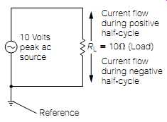
FIG. 3 Simple AC circuit illustrating current flow reversal.
If the AC voltage shown in Fig. 2 were applied to a load, as shown in Fig. 3, current would flow in a back-and-forth motion, proportionally following the voltage variations. Some quantity of power would be dissipated because current is flowing through the load. The power dissipated, while the current flows in one direction, does not negate the power dissipated when the current reverses (there is no such thing as negative power). Therefore, power is being dissipated continuously. Consider the previous analogy of the car driving back and forth in the driveway.
Although it ended up where it began, energy (gasoline) was consumed, and work was performed (back and forth movement of the car).
A practical method of comparing AC voltage and current to a DC equivalent is the result of a complicated mathematical analysis called root mean square (rms). In other words, AC rms sources can be directly compared to DC sources in their ability to provide power, or to perform work. For example, the common 120 volts AC from household outlets is an rms rating. It can perform just as much work as 120 volts of DC. Values of rms are often called effective values.
To calculate the rms value of a sine wave, simply multiply the peak value by 0.707. Referring to Fig. 2, the peak amplitude of the sine wave is 10 volts. To find the rms voltage, the 10 volts is multiplied by 0.707, providing the result of 7.07 volts. FIG. 3 illustrates this same AC voltage being applied to a load. The power this load dissipates is the same power it would dissipate if a 7.07-volt DC source were applied to it.
AC Calculations
All of the following equations and calculation methods are applicable only to sinusoidal wave voltages and currents. Virtually all AC used for power sources will fall into this category, so you will be using this information frequently.
If you know the peak, or peak-to-peak, value of a sine-wave AC voltage or current, you can calculate the rms value using Eq. ( 3) or ( 4):
rms _ (peak value)0.707 ( 3)
rms _ (1 _2 peak-to-peak value)0.707 ( 4)
The AC voltage shown in Fig. 2 can be accurately defined as being 7.07 volts rms. This means it is equivalent to 7.07 volts DC. Rms current calculations are performed in the same manner.
If an rms voltage or current is known, and you wish to calculate the peak or peak-to-peak value, Eqs. ( 5) and ( 6) might be used:
Peak _ (rms value)1.414 ( 5)
Peak-to-peak _ (peak value)2 ( 6)
For example, common household outlet voltage is 120 volts AC rms. The peak and peak-to-peak values might be calculated as follows:
Peak _ (rms value)1.414
Peak _ (120 volts)1.414 _ 169.68 volts
Peak-to-peak _ (peak value)2
Peak-to-peak _ (169.68 volts)2 _ 339.36 volts
You can use any of the AC voltage or current terms in the familiar Ohm's law equations. The only stipulation is "they must be in common." In other words, you cannot mix up rms, peak, and peak-to-peak values, and still arrive at the correct answer. For example, if you wanted to use Ohm's law (E = IR) to calculate a peak voltage, you must use the associated peak current value. Resistance is a constant value; therefore, it cannot be expressed in terms such as peak, peak-to-peak, or rms. For the following examples, refer to Fig. 3.
Inductance
At some point in your life (possibly in a school science class), you might have built a small electromagnet by twisting some insulated electrical wire around a nail, and then connecting the ends of the wire to a flash light battery, as shown in Fig. 4. An electromagnet is an example of an inductor. An inductor is simply a coil of wire.
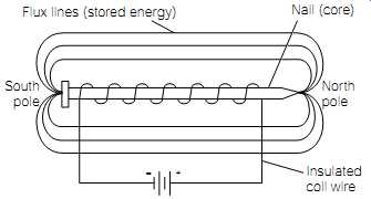
FIG. 4 Simple electromagnet.
A typical inductor will consist of a coil (or multiple coils) wound on a metallic, ferrite, or phenolic core. The metallic and ferromagnetic cores concentrate the magnetic flux lines (lines of force), thus increasing the inductance value. Some coils used in high-frequency applications contain tunable ferrite slugs that allow adjustment of the inductance value. Other types of high-frequency, or special-purpose, inductors do not contain metallic cores. These are referred to as air core coils.
The electromagnet shown in Fig. 4 illustrates how a coil will develop an electromagnetic field around it. An electromagnetic field is made up of many lines of force called flux lines. The flux lines flow through the nail, causing it to become a temporary magnet. Electromagnetic flux lines are stationary only as long as the current flow through the coil is constant. If the current flow through the coil is increased, the electro magnetic field will expand, causing the flux lines to move outward. If the current flow is decreased, the electromagnetic field will collapse, causing the flux lines to move inward. The most important thing to understand is that the field will move (expand and contract) if the current flow changes. Remember this foundational rule of electricity:
Whenever an electrical conductor (wire) cuts magnetic flux lines, an electrical potential (voltage) will be induced in the conductor.
It also stands to reason that if the conductor in the previous statement is part of a closed circuit, an induced current will flow whenever an induced voltage is generated. This is the basic principle behind the operation of any electrical generator. To generate electricity, magnetic flux lines must be cut by a conductor. This can be accomplished by moving either the conductor or the electromagnetic field.
As stated previously, if the current flow through a coil (inductor) is varied, the electromagnetic field will move in proportion to the variance. The movement of the electromagnetic field will cause the coil conductors to be cut by the changing flux lines. Consider these effects under the following three conditions:
1. A coil has a steady and continuous current flow through it; the applied voltage to the coil is held constant. Thus, the electro magnetic field surrounding the coil is also constant and stationary.
2. The applied voltage to the coil is reduced. The current flow through the coil tries to decrease, causing the electromagnetic field surrounding the coil to collapse by some undetermined amount. As the field collapses, the flux lines cut the coil wire generating a voltage that opposes the decrease in the applied voltage. The end result is that the coil tries to maintain the same current flow (for a period of time) by using the stored energy in the electromagnetic field to supplement the decreased current flow.
3. The applied voltage to the coil is increased. The current flow through the coil tries to increase, causing the electromagnetic field surrounding the coil to expand. As the field expansion occurs, the flux lines cutting the coil wire generate an opposing voltage. The end result is that the coil tries to maintain the same current flow (for a period of time) by storing energy into the electromagnetic field.
In essence, an inductor tries to maintain a constant current flow through itself, by either expanding or contracting its associated electro magnetic field. This expansion or contraction of the electromagnetic field generates a voltage that opposes any changes in the applied voltage.
This opposing voltage is referred to as counter-electromotive force (cemf).
Electromotive force is another name for voltage.
Inductors are storage devices; electrical energy is stored in the electro magnetic field surrounding an inductor. The quantity of energy that an inductor is capable of storing is called its inductance value. Inductance is measured in units called henrys. One henry is the inductance value if a current change of 1 ampere per second produces a cemf of 1 volt. The electrical symbol for inductance is L.
Although this might seem somewhat complicated at first, consider the circuit shown in Fig. 5. (Note the symbol for an inductor. The vertical lines to the right of the wire turns denote an iron core.) With the switch (S1) in the open position, obviously there cannot be any current flow through the inductor. The graph illustrated in Fig. 6 shows the response of the current flow immediately after the switch in Fig. 5 is closed. The inductor tries to maintain the same current flow that existed prior to the closing of the switch (which was zero in this case), by storing energy in its associated electromagnetic field. While the electro magnetic field is expanding, a reverse voltage (cemf) is being generated by the coil opposing the applied voltage. The end result, as shown in Fig. 6, is that the current takes time to change even though the voltage is applied instantaneously.
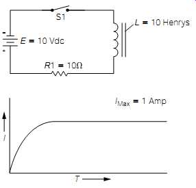
FIG. 5 Basic LR (inductive resistive) circuit.
FIG. 6 Circuit current response of Fig. 5.
The time period required for the current to reach its maximum value is measured in seconds, and is defined by a unit called the time constant, which is the time required (in seconds) for the current flowing through the inductor to reach approximately 63% of its maximum value. The time constant is found through dividing the inductance value by the circuit resistance. For example, the time constant for the circuit shown in Fig. 5 would be:
Tc __ _ 1 second
10 henrys
__ 10 ohms L
_ R
Assume that the maximum obtainable current of the circuit shown in Fig. 5 is 1 amp. According to the previous time constant calculation, the circuit current will climb to a value of 0.63 amp (63% of 1 amp) after the switch has been closed for 1 second. During the next 1-second time interval, the current will increase by another 63% of the difference between its present level and the maximum obtainable level. In other words, if the current rose to 0.63 amp after the first time constant, that would leave a 0.37 amp difference between its present level and the maximum level of 1 amp (1 amp - 0.63 amp = 0.37 amp). Therefore, during the second time constant, there would be a current increase of 63% of 0.37 amp, or approximately 0.23 amp. This results in a circuit current of approximately 0.86 amp after two time constants. Likewise, during the third time constant, there would be another current increase of 63% of the difference between the present level and the maximum obtain able level, and so on.
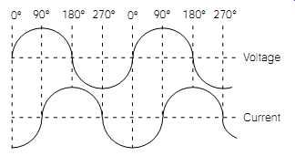
FIG. 7 Voltage-current phase relationship in an inductive circuit.
In theory, the maximum steady-state current of an LR circuit can never be obtained; it would always be increasing by 63% of some negligible current value. In a practical sense, the maximum circuit current value is usually assumed to have been reached after five time constants.
The current flow of the circuit shown in Fig. 5 would reach its maximum 1-amp level in approximately 5 seconds after S1 is closed.
The effect of the current taking time to catch up with the applied voltage is called the current lag. When the applied voltage is AC (changing constantly), the current will always lag behind the voltage.
Periodic AC voltages are divided up into degrees, like a circle. Just as a complete circle will contain 360 degrees, one complete cycle of AC is considered as having 360 degrees. FIG. 7 illustrates how one complete cycle of sine-wave AC voltage is divided into 360 degrees. Note how the positive peak is at 90 degrees, the end of the first half-cycle occurs at 180 degrees, the negative peak is at 270 degrees, and the end of the cycle occurs at the 360-degree point. The waveform below the voltage wave form is the current waveform. Note how the current lags behind the voltage, its first peak occurs at 180 degrees, the end of the first half-cycle is at 270 degrees, and so forth. In other words, the current is out of phase with the voltage by 90 degrees.
The waveforms shown in Fig. 7 are characteristic of any "purely inductive circuit" (a circuit consisting only of an AC source and an inductor, or multiple inductors). In a purely inductive circuit, the current will always lag the voltage by 90 degrees, regardless of the applied AC frequency. This voltage-current phase differential is often referred to as the phase angle, and it is also stated in terms of degrees.
An interesting consideration in purely inductive circuits is the power consumption-there is none! To understand why, refer back to Fig. 7.
For discussion purposes, assume the peak voltage waveform levels to be 10 volts, and the peak current waveform levels to be 10 amps. At the 90-degree point, the voltage is at its peak level (10 volts) and the current is at zero. Using the power equation P = IE, the instantaneous power dissipation can be calculated:
P =IE =(0)(10 volts) =0
At 180 degrees, the voltage is at zero, and the current is at its peak of 10 amps. Using the same power equation
P =IE =(10 amps)(0) =0
At 270 degrees, the voltage is at its negative peak of -10 volts, and the current is zero. Again, using the same power equation
P =IE =(0)(10 volts) =0
Because of the 90-degree phase differential between voltage and current, the power dissipation in any purely inductive circuit is considered to be
virtually zero. The inductor continually stores energy and then regenerates this energy back into the source.
Assume that you were examining a purely inductive circuit possessing the voltage and current waveforms shown in Fig. 7. Again, assume the peak voltage amplitude to be 10 volts, and the peak current amplitude to be 10 amps. If you used a voltmeter to measure the applied voltage, it would read 7.07 volts; the rms value of 10 volts peak. Likewise, if you used an ammeter to measure the current flow, you might read 7.07 amps, the rms value of 10 amps peak. If you multiplied the measured voltage value by the measured current value, the answer should be the rms (or effective) power value (P =IE). The answer would be 50 watts rms (7.07 volts times 7.07 amps =50 watts). This contradicts the previous statement regarding zero power dissipation in a purely inductive circuit. The reason for this discrepancy is that you did not take the voltage and current phase differential into consideration. In a purely inductive circuit, the power calculation based on the measured voltage and current values is called the apparent power. The actual power dissipated in an inductive circuit when the voltage and current phase differential are taken into consideration is called the true power.
If you wish to pursue higher mathematics, true power is calculated by finding the apparent power, and then multiplying it by the cosine of the differential phase angle. For any purely inductive circuit, the differential phase angle (as stated previously) is 90 degrees. The cosine of 90 degrees is zero. Therefore, zero times any apparent power calculation will always equal zero. (If you don't understand this, don't worry about it. Depending on your interests, you might never need to perform these calculations; but if you do, a good electronics math book will explain it in "easy" detail.) Another term related to inductive circuits is called the power factor.
The power factor of any circuit is simply the true power divided by the apparent power.
Power factor = true power/ apparent power
DC Resistance
Earlier in this section, the time constant of the circuit in Fig. 5 was examined and the maximum obtainable current flow was found to be approximately 1 amp. The analysis and calculations of this circuit were performed by assuming the circuit to be "ideal"; that is, all components were considered to be perfect. With any circuit, and with all components, there are shortcomings that cause them to be something less than perfect in their operation. To become very technically accurate regarding the circuit in Fig. 5, you would have to consider such factors as the internal resistance of the battery (source resistance), the wiring resistance, the resistance of the switch contacts of S1, and the DC resistance of the inductor.
In the majority of design situations, all of these factors are so low that they are considered negligible. But to fully understand the operation of inductors, the DC resistance factor should be discussed.
Referring back to Fig. 5, it was stated that after five time constants, the circuit current would reach its maximum amplitude. From this point on (assuming that S1 remains closed), both the voltage and current will remain stable. Therefore, the electromagnetic field around the coil will also remain stable. If the electromagnetic field does not move, the wire making up the coil cannot cut flux lines. This means there cannot be any generation of cemf. In effect, the only opposition to current flow posed by the inductor is the wire resistance of the coil. The coil's wire resistance (usually called the DC resistance) is normally very low and might be disregarded in most applications.
A term for defining the DC resistance of any coil relative to its inductance value is Q (abbreviation for quality). The Q of an inductor is the inductance value (in henrys) divided by the DC resistance (in ohms):
Q = L / R
For most inductors, this value will be 10 or higher.
Transformers
An inductor with two or more coils wound in close proximity to each other is called a transformer. (A single-coil inductor is often called a "choke.") If an AC voltage is applied to one coil of a transformer, its associated moving magnetic field will cause the magnetic flux lines to be cut by itself (causing cemf ) and any other coil near it. As the other coils are cut by flux lines, an AC voltage is also induced in them. This is the basic principle behind transformer action.
If the multiple coils of a transformer are wound on a common iron core, the transfer of electrical energy through the moving electromagnetic field becomes very efficient. Iron-core transformers are designed for efficient transfer of power, and are consequently called power transformers or filament transformers (an older term from the vacuum-tube era). Properly designed, power transformers can obtain efficiencies as high as 99%.
FIG. 8 illustrates some examples of transformer symbols. The coil on which the AC voltage is applied is called the primary. The transfer of power is induced into the secondary. Transformers might have multiple primaries and secondaries. The primaries and secondaries might also contain "taps" to provide multiple voltage outputs or to adapt the transformer to various input voltage amplitudes. The example shown on the left side of Fig. 8 is a transformer with one primary and one secondary. The illustration on the right side shows a transformer that has two primaries, one secondary, and a secondary tap. If a tap is placed in the exact center of a transformer coil, that coil is said to be center-tapped (ct).
The most important attribute of a power transformer is its ability to increase or decrease AC voltage amplitudes without a significant loss of energy. This is accomplished by means of the turns ratio designed into the transformer. The turns ratio is simply the ratio of the number of turns on the primary to the number of turns on the secondary. For example, if a transformer has a 1:1 turns ratio, it has the same number of turns on the primary, as it has on the secondary. A transformer with a 2:1 turns ratio has twice the number of turns on the primary, as on the secondary. A transformer with a 1:12 turns ratio has 12 times the number of turns on the secondary, as on the primary. In the ratio expression, the primary is always represented by the first number of the ratio, and the secondary is the second.
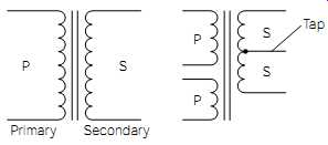
FIG. 8 Transformer symbols.
The turns ratio has a directly proportional relationship to the transformer's voltage amplitudes. If the secondary of a transformer has more turns than the primary, the secondary voltage will be proportionally higher in amplitude, or "stepped up." If the secondary contains less turns than the primary, the secondary voltage will be proportionally lower, or "stepped down." For example, if a transformer has a 2:1 turns ratio, the secondary voltage will be one-half the amplitude of the applied voltage to the primary. This is because there is only one-half the number of turns on the secondary as compared to the primary. The reverse is also true. If the transformer has a 1:2 turns ratio, the secondary voltage will be twice that of the primary.
A basic law of physics tells us that it is impossible to obtain more energy from anything than is originally put into it. For this reason, if the secondary voltage of a transformer is doubled, the secondary current rating will be one-half the value of the primary. Similarly, if the secondary voltage is only one-half the primary voltage, the secondary current rating will be twice the value of the primary. In this way, a transformer will always maintain an equilibrium of power transfer ability on both sides. The maximum power transfer ability of a transformer is called its volt-amp (VA) rating.
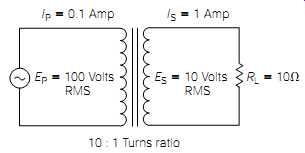
FIG. 9 Transformer with secondary load demonstrating the relative primary
and secondary currents.
This principle is demonstrated in Fig. 9. Note that the transformer has a 10:1 turns ratio. This means that whatever voltage is applied to the primary (Ep ) will be reduced by a factor of 10 on the secondary (Es ).
The current flow is just the opposite. The current flowing through the load resistor (I s ) will be 10 times greater than the primary current flow (I p ). In this illustration, Ep is 100 volts rms. Because there is only one-tenth the number of turns on the secondary, Es is 10 volts rms.
According to Ohm's law, the current flow through the load resistor will be 10 volts rms divided by 10 ohms, or 1 amp rms. Therefore, the power transferred to the secondary load will be
P = IE = (1 amp rms)(10 volts rms) = 10 watts rms
Now consider the power being delivered to the primary. The current in the primary will be one-tenth that of the secondary, or 0.1 amp rms.
Because Ep is 100 volts rms:
P =IE =(0.1 amp rms)(100 volts rms) =10 watts rms
It is important to understand that the transformer is not dissipating 10 watts rms of power. It is transferring 10 watts rms of power from the primary to the secondary. The transformer itself is dissipating a negligible amount of power. If the secondary circuit were opened, the current flow in the secondary would consequently drop to zero. Similarly, the current flow in the primary would also drop. (A smaller current flow would still remain in the primary. The explanation and calculations for this condition will be covered in Section 15.)
Soldering
Enough of the theory stuff-if you please!! If you're thinking that about now, it just means you're human. If you have comprehended "most" of the theory covered in Section 2 and in this section, you are doing just fine. The fuzzy areas of understanding will clear up as you begin to physically work with components and circuits. The remainder of this section will deal with the beginning steps for constructing a lab oratory quality power supply. This power supply will become the power source for many of the future projects in this guide and, hopefully, many more of your own.
Before beginning any kind of electrical or electronics construction, it is essential to become proficient at soldering. By now, you should have accumulated the basic tools needed to solder (as covered in Section 1):
- A soldering iron with several size tips
- A soldering iron holder
- A damp sponge for tip cleaning
- A roll of good-grade, 60/40 rosin-core solder (if you have any "acid core" solder, throw it away or give it to a plumber!)
- A desoldering tool
In addition to these specific items, you will need a few small hand tools, a comfortable, well-lighted place to work, a little patience, and a work table (please don't try this on an expensive piece of furniture!). A little steel wool and some isopropyl alcohol might come in handy for cleaning purposes.
Soldering Overview
Soldering is a process by which conductive materials are electrically and mechanically bonded together with a tin-lead alloy by the application of heat. For the bonding process to occur properly, the solder and the materials being soldered must be of sufficient temperature. The materials being soldered must also be clean and free of corrosion, oil, and dirt.
During the actual soldering process, the soldering iron is used to heat the material to be soldered (such as a component lead, bare wire, or the copper "artwork" on a printed circuit board) until it reaches a temperature above the melting point of the solder. Rosin-core solder is then placed on the material to be soldered and allowed to melt. As it melts, it will flow outward (called wetting) toward the soldering iron tip. When sufficient solder has flowed for a good electrical and mechanical bond, the soldering iron tip and the unused solder are removed simultaneously. The newly formed solder connection is given time to cool and solidify. After cooling, it should appear bright, shiny, and smooth. A rough or grainy looking joint (a cold joint) is questionable, and should be redone.
Soldering for the First Time
If you have never tried soldering, I'm sure you probably think it is more difficult than it is. My experience in working with beginning students has taught me that if I just give them a few pointers and leave them alone, they will quickly get the hang of it.
Safety note: Wear safety glasses or goggles to protect your eyes when soldering. Also, work in a well-ventilated area, and don't inhale the smoke.
To begin, you will need something to practice on. I recommend a scrap of printed circuit board. Printed circuit boards (commonly called PC boards) are thin sheets of phenolic or fiberglass material with electronic components mounted on them. The electronic components interconnect on the board by means of copper foil "artwork," called traces, glued to the PC board. These are easy to come by. Virtually any kind of junk electronic equipment will contain at least one PC board. If it is difficult to obtain a scrap PC board, you can purchase a general-purpose "grid board" from your local electronics supply store, together with a bag of miscellaneous electronic components. Buy the cheapest you can find; the board and the components will probably be scrap by the time you're comfortable with soldering.
When you've collected the tools, materials, and something to practice on, it's time to try your first soldering exercises. Plug in the soldering iron and allow it time to warm up. If you have a soldering iron with an adjustable tip temperature, set it to about 670 degrees. If your soldering iron is adjustable, but doesn't have a readout (in degrees), initially set it to a low temperature, and adjust it by trial and error. The tip should be hot enough to readily melt the solder, but not hot enough to "instantly" melt the solder while producing a lot of smoke.
If the tip of the soldering iron is not silver and shiny, it will need to be "tinned." Clean the tip with some steel wool and apply a little rosin core solder all around the tip and about a half-inch up on the tip. Make sure the solder flows evenly around the tip and then wipe the tip on the damp sponge to remove any excess solder. As the soldering iron is used, it will be necessary to periodically re-tin the tip whenever flux or other contaminates build up on the tip causing it to turn dark. If you remember to clean the tip frequently with the damp sponge, the need for re tinning will be reduced. If the tip becomes dark quickly, even when not in use, the tip temperature is probably too high.
Soldering Procedure
If you have a scrap PC board to practice on, you will probably have to remove a few components before soldering them back. Skip this section and go on to the next section entitled Desoldering Procedure. Return to this section after you have finished desoldering.
Make up a few practice solder joints by placing some components randomly in the PC board. Before trying to solder, examine the joint to be soldered. It should be clean, free of corrosion, and mechanically stable (held in place). Place the soldering iron tip on all of the material to be soldered. If you are soldering on a PC board, this means the soldering-iron tip should be placed on the PC board foil material, and on the component lead at the same time. All of the material to be soldered must be heated, or the solder will not adhere properly. With the joint properly heated, apply the solder to the joint (not the soldering-iron tip).
Allow the solder to flow evenly around the joint, and eventually flow to the tip. Remove the unused solder and the soldering iron from the joint, and allow it to cool.
Examine the newly soldered joint. It should be shiny and smooth, and the connection should be mechanically strong. If the solder balled up on the joint, it probably wasn't hot enough. A rough, gray-looking joint is also indicative of improper heating. If the soldering-iron tip is not properly tinned, it will not conduct heat adequately to the solder able material. A solder joint with poor electrical integrity is referred to as being "cold." A cold solder joint will not be mechanically solid, either.
Wiggle the newly soldered component to verify it is tightly bonded together.
The real skill in soldering relates to the speed at which it can be performed. You should be able to solder a typical connection in well under 5 seconds. Heating a connection involving solid-state components for too long can destroy the components. Most electronic supply stores sell aluminum clamp-on heatsinks to conduct most of the heat away from the component when soldering. But the usefulness of these devices is limited.
Most integrated circuits, and many miniature components, simply do not have an available lead length onto which to clamp.
Another point to consider, when soldering is heat buildup. Suppose that you are soldering a component with eight leads into a PC board. If you solder all eight connections, one immediately after another, the component might become very hot because of heat buildup. It becomes progressively warmer with each soldering because it did not thoroughly cool from the previous one. The solution is to allow sufficient time for the component to cool between solderings.
Desoldering Procedure
Desoldering, of course, is the opposite of soldering. Desoldering is required to change defective components, to correct construction errors, to redo wiring jobs, and to salvage parts.
One commonly used method of desoldering utilizes pre-fluxed cop per braid to absorb molten solder by capillary action. The desoldering braid, or wicking, goes by a variety of brand names and is easy to use.
The braid is simply placed in the molten solder, and the capillary action draws the excess solder up into the braid. The used piece of braid is then cut off and discarded. For smaller solder joints, the action is often improved by sandwiching the braid between the soldering iron tip and the joint to be de-soldered.
Most people prefer to use a vacuum desoldering tool as described in Section 1. Desoldering is accomplished by "cocking" the tool: holding the tip close to the joint to be de-soldered, melting the solder with a soldering iron, and pressing the "trigger" on the tool. The rapid suction action sucks the excess solder up into a holding chamber, from where it is removed later. This tool is often called a solder sucker.
If you plan on doing a lot of desoldering (for salvage purposes, for example), you might want to consider investing in a dedicated desoldering station. These units contain a dedicated vacuum pump and a specially designed soldering iron with a hollow tip. The molten solder is sucked up through the hollow tip of the iron and held in a filtered container for removal. The suction action is triggered by a foot or knee pedal. Unfortunately, dedicated desoldering stations are very expensive. Be sure you can justify the cost before investing in one.
Assembling and Testing the First Section of a Lab Power Supply
Now comes the fun part! In this section you will begin to build a lab quality power supply that you can use as a power source for many other projects throughout this guide. The building of this supply is also a learning process. You will perform checks and tests to drive home the theories and principles you have learned thus far. The experiments performed will also verify the accuracy of your understanding. The same procedure will be followed for virtually every project in this guide, so upon completion, you not only have some "neat" projects to show off, but you also have the practical and theoretical knowledge to go with them (which is more important by far!).
Emphasis on Safety throughout This Guide
Please don't think I sound like your mother, but if that's what it takes to save even one reader from having an unfortunate accident, the price is well worth it. You learn by doing, but you live to tell about it if you do it right! Never compromise on safety.
Before beginning construction, let me briefly explain some of the features that this power supply will have on completion. This supply will have two independently adjustable, voltage-regulated outputs; one positive, and one negative. The adjustment range for each will be from about 4 to 15 volts. It will be short-circuit protected (so you can make a "goof" without destroying part of the supply), and it will go into current limit mode at about 1.5 amps. The current limit feature allows the power supply to double as a battery charger (with certain precautions). A handy feature will be two additional fuse protected "raw" DC outputs (+ and -34 volts) for testing audio amplifiers, or powering higher voltage projects.
In short, you will discover it to be a versatile and valuable piece of test equipment.
Materials Needed for Completion of This Section Throughout the remainder of this guide, I will always assume that you have a DVM (or equivalent), soldering tools, alligator clip leads, hook-up wire, mounting hardware, and the necessary hand tools. The materials list for each project will only list the materials and components actually used in the project itself.
[Quantity 1 1 1 1 2 1 1 1 ]
[ Item Description 19 _ 9 _ 3 (w _ d _ h)-inch (or larger) metal project box
Grounded (3-conductor) power cord
Power-cord strain relief
SPST 10-amp on-off switch
24-volt at 2-amp transformers (120-volt primary)
3AG size ( 1 _4 _ 11 _4-inch) fuse block or fuse holder
2-amp 250-volt slow-blow fuse
Locking terminal solder lug (see text)]
The project box doesn't have to be fancy and expensive unless you're the type that wants to go first class all the way. The enclosure from a junked CD player or VCR should do nicely, provided you rework the front panel. (Front panels can be modified to accommodate almost any need by placing a sheet of chassis aluminum over the face of the original front panel. This hides the original front panel artwork, covers the holes, and provides a solid mounting for new hardware. Because the front panels on most consumer electronic equipment is made from plastic, the aluminum sheet can be easily mounted with self-tapping screws.) The project box can be much larger than specified; it is strictly a matter of personal preference. The bottom part of it must be metal, however, because it will be used for "heatsinking" purposes in a later construction section.
The power cord must have a ground wire; that is, it must have three prongs (ground, neutral, and hot). Also, be sure to use the proper size strain relief for the power cord. Do not use a rubber grommet in place of a strain relief; this could be dangerous in the long run.
Try to find an on-off switch that comes complete with a backplate to indicate its position, or some other means of indicating its status. It's easy to forget which way is on and which way is off with a bench full of parts and equipment.
This power supply design is a little unusual because it incorporates the use of two 24-volt transformers to form a single 48-volt center-tapped transformer. I decided to design it this way because it might be a little difficult to find a 48-volt ct transformer; however, 24-volt, 2-amp trans formers are common.
The specified fuse is the common glass type, as used in a variety of electrical/electronics equipment, and in many automobiles ( 1/4 inch in diameter and 1 1/4 inch long). Be sure the fuse holder or fuse block is made for that type of fuse. I would personally recommend fuse blocks because they are easier to mount, but that will depend on your preference, and what you might already have in the junk box.
A locking terminal solder lug looks like a small internal tooth lock washer with an arm, or extension, sticking out of it. The extension will have one or two holes in it for wire connections. They can be bolted down to a chassis or PC board in the same manner as any other lock washer, but the extension provides a convenient solderable tab for connection purposes. One of these will be used in this project for connecting the ground lead of the power cord to the chassis.
For this particular project, the component placement, enclosure size, and various component construction parameters (such as physical dimension, mounting holes, color) are not critical to the functional operation of the finished project. This allows you the freedom to be creative and save some money, depending on what you might already have, or what can be obtained through salvaging.
I must assume, at this point in the guide, that you are inexperienced at buying electronic parts (if I'm wrong, please forgive me). Chances are, you will purchase some (or all) of this material list from a local electronics supply store. This might be slightly traumatic for some people, so let me give you some encouragement and advice. Don't feel intimidated because you happen to be a novice! You are to be commended because you are learning and accomplishing something that many people are afraid to try. The personnel who work in an electronics supply store should be in total agreement with me on that point. Never be reserved about asking any questions you might have about purchasing the right materials and components for your projects. If any sales person ever makes you feel "low" because of your inexperience, I hope you bring this guide into the store, and let that person read this paragraph. Then walk out, and take your hard-earned money to a different store that employs sales personnel with the right attitude.
Mounting the Hardware
Read this entire paragraph before physically mounting any components. Lay out the components in the enclosure for mounting. FIG. 10 illustrates a top view of the approximate way the components should be mounted to the bottom of the enclosure; it is assumed that the top cover has been removed. The transformers should be placed side by side in either rear corner. Most transformers of this size are constructed with the primary connections on one side, and the secondary connections on the other. Be sure that the primary connection sides are facing the rear panel.
The transformers should be placed far enough away from the rear panel to allow sufficient room for the fuse block, or the fuse holder, to be mount ed. If you are using a fuse holder instead of a block, pay careful attention to how far it extends "into" the enclosure after mounting; this distance tends to be more than you would guess at first glance. If you are using a fuse block, it should be mounted close to the primary of each transformer.
The power cord and strain relief assembly should come into a convenient location close to the fuse block or fuse holder.
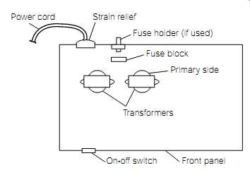
FIG. 10 Approximate component layout for first section of power sup
ply project.
The on-off switch is mounted to the front panel. Note how it should be on the same side (in the front) as are the transformers in the back. In regard to height, the power cord and strain-relief assembly, the fuse holder (if used), and the on-off switch should be placed about half way up the height of the enclosure. Double-check all of the mounting considerations in this paragraph; and if everything looks good, go ahead and mount the components in the enclosure, using whatever hardware is applicable (nuts, bolts, screws, washers, etc.).
Wiring and Testing Procedure
Do not attempt to apply power to the power supply until all of the tests are performed and understood. Do not attempt to perform any tests using your DVM until you have read and understood the owner's manual for your particular DVM. Even though a general procedure for using a DVM will be provided throughout this section, this is not a substitute for thoroughly understanding the particularities of your personal instrument.
Refer to Fig. 11 during the course of this wiring procedure. Look at the male outlet plug on the power cord. It should have three prongs; two will be flat "blade"-type prongs, and the third will be round.
The round prong is the earth ground connection. The green wire on the other end of the power cord attaches to this round prong. Verify this using the DVM in the "ohms" position. Touch one DVM test probe to the round prong and the other to the green wire; you should read very close to zero ohms. Using a DVM in this way is called testing for continuity. In other words, you have proved that there is a continuous electrical path from the round prong, on the plug end of the power cord, to the green wire on the other end. If, by chance, you have a power cord without color-coded wires, test all three wires on the chassis end of the power cord to determine the one connected to the round prong. Solder the wire (connected to the round prong) to a locking terminal solder lug, run the cable through the strain-relief hole, and bolt the solder lug to the metal chassis bottom, underneath the power cord strain relief.
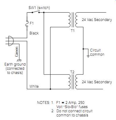
FIG. 11 Schematic diagram of first section of lab power supply.
NOTES: 1. F1 = 2 Amp, 250 Volt "Slo-Blo" fuses; 2. Do not connect circuit common to chassis
Obtain some 18- to 20-gauge hookup wire with an insulation rating of at least 200 volts. Cut two lengths of this wire long enough to reach from the on-off switch to about 3 inches beyond the rear of the chassis, so they can be routed along the chassis bottom. Solder these two wires to the on-off switch connections. Connect one of the switch wires to one of the fuse block lugs. In a later step, the other fuse lug will be used to connect the power cord's hot lead.
Connect the other switch wire to one side of the T1 primary lugs, or wires. Some units will have metal lugs; others will have insulated and color-coded wire leads. Connect another piece of hookup wire from this same point (T1) to the same side of the T2 primary. Solder both of these connections. Now take a few moments to compare your wiring progress so far, with the schematic diagram illustrated in Fig. 11.
If you must connect two or more wires together to make these connections, be sure that the connection is well insulated with either insulated mechanical connectors, or soldered and covered with heat-shrink tubing. You might use an insulated "butt splice" connector, or an insulated "wire nut"-type connector. When soldering two wires together and using a length of heat-shrink tubing to insulate the connection, remember to install the tubing onto one of the wires before you twist and solder the ends. The tubing must be just large enough to fit over the twisted and soldered splice. Heat the tubing with a hair dryer, or a heat gun, until it shrinks tightly around the splice; tight enough to remain in position permanently. I do not recommend using electrical tape to insulate this type of connection.
Refer to Fig. 11 and note how one side of the F1 fuse block (or holder) is connected to SW1. Connect the other side of the F1 fuse block (or holder) to the black-wired hot side of the AC power cable. This black wire should show continuity to the smaller one of the two flat blades at the other end of the power cable.
You should have one white (neutral) power cord wire left. Connect it to the unused primary lug (or wire) of T2. Also, connect a piece of hookup wire from this connection to the unused side of T1. Double-check all wiring with the schematic diagram in Fig. 11, and solder all connections.
Note that the primaries of T1 and T2 are wired in parallel (Fig. 11).
The bottom of T1's primary is connected to the bottom of T2's primary.
And, the top of T1's primary is connected to the top of T2's primary.
The secondaries of T1 and T2 are to be wired in series. The bottom of T1's secondary is connected to the top of T2's secondary. You must relate this to the way your transformers are constructed.
Let me attempt to walk you through this. Look at your transformer's secondary connections. If there are three connections for each secondary, it means they are center-tapped secondaries. Disregard the center tap connections; they will not be used for this project. That leaves you with two connections for each secondary. Most transformers are constructed so that one connection will be on the left side of the trans former, and one on the right side. Simply connect the left side of one secondary to the right side of the other, and they should be in series, as shown in Fig. 11. Make this wiring connection to the best of your ability. If it's wrong, it won't hurt anything; and you can correct it in the following section.
If your transformers have leads, these wires will be coded. The two (usually) black wires are for the primaries. The secondary leads will normally exit the unit on the opposite side from the primary leads. These leads might be any solid color (red, green, yellow, etc.). If three leads are there, the multicolored (red/yellow; red wire with yellow stripes) lead is the center tap. Connect the "left-hand" red lead of one unit, to the "right-hand" red lead of the other unit. This will stack them in series, and with the correct phase. Insulate each of the center-tap leads from each other, and from other circuit components, with wire nuts, or with shrink tubing.
Testing the First Section of the Lab Power Supply
There are two purposes for testing your work thus far. It is important, in regard to function and safety, to be sure that the construction you have completed to this point is correct. But it is just as important, in regard to theory and practicality, to understand the testing procedure. If you become confused, go back and review the area of your confusion. It will be time well spent.
Do not apply power to the power supply yet. If you have installed fuse F1 into the fuse block (or holder), remove it. Place the on/off switch in the "off" position. Adjust your DVM to read resistance ("ohms" position), and set it for the lowest resistance range available. Measure the resistance across the two blade prongs of the power cord. Take the same type of measurement from each blade to the round earth ground prong. All three of these readings should be "infinite" (meaning an open circuit or no continuity). Take the same measurement from the round earth ground prong to any point on the metal chassis. This reading should be very close to zero. This is because you connected the earth ground wire directly to the chassis through the locking terminal solder lug.
Now place SW1 in the "on" position. Again, take a resistance reading between the two blade prongs on the power cord. Again, this reading should be infinite because the fuse is not installed. Install F1 into its fuse block (or holder). Again, measure the resistance between the two blade prongs. This time, you should get a very low resistance reading (about 4 to 7 ohms). Referring back to Fig. 11, with SW1 closed and F1 installed, you are actually reading the parallel DC resistance of the T1/T2 primaries.
The resistance of each of these primaries is actually twice what this reading has indicated. To illustrate this fact, take two equal value resistors; 100 ohms each, for instance. Measure each resistor; they should each register approximately 100 ohms. Now, twist the ends of the resistors together, so that they are connected in parallel. The measured resistance should now be about 50 ohms. The paralleled resistors represent the paralleled primaries of the power transformers. Your blade-to-blade measurement across the two primaries, just as across the two resistors, shows a value of one-half of the actual primary resistance, and it demonstrates continuity.
Your reading is the equivalent resistance (Requiv ) of the primaries.
Now, turning your attention to the transformer secondaries, measure the resistance between T1's secondary connections. This should be a very low reading, usually less than 1 ohm. Record this value. Similarly, measure T2's secondary resistance. Record this value. Now, measure the resistance from the unconnected side of the T1 secondary to the unconnected side of the T2 secondary. Because the two secondaries are in series, the last measurement should be the sum of the first two secondary measurements. As discussed in Section 2, to calculate the total series resistance, you simply add the individual resistance values.
As a final safety measure, take a resistance measurement between either secondary connection and the primary connection of T1/T2 at the power switch. This reading should be infinite. This proves that there is isolation (no direct wiring connection) between the primaries and the secondaries of T1 and T2. Do the same test between the secondary leads and the chassis ground, and verify that you achieve the same results.
This verifies that the secondaries are not shorted (short-circuited) to ground. Consider the following safety tips before proceeding.
CAUTION
Serious injuries, resulting from electrical shock, can occur in several ways. One form of injury is through the indirect effect of electrocution. On receipt of a high-voltage shock, the human body's automatic response is to involuntarily contract the muscles in and around the affected tissue.
In other words, you jerk away from it really quick! If, for example, you receive a nasty shock to your arm, and your arm happens to be close to some sharp metal edges, you are likely to cut a major size gash in your arm as it jerks back against the sharp metal. This is an indirect injury.
The arm wasn't actually cut by the electricity, but the effect of the electrical shock caused the injury. I learned a long time ago that you don't bend over and curiously watch someone working on a TV from behind.
You could get your jaw broken! Serious injuries resulting directly from electrical shock can be in the form of burns. This occurs more often in very high-voltage environments, such as those encountered by power company employees and industrial electricians.
But the most dangerous form of injury occurs when an accident or circumstance arises causing electrical current to pass through a person's vital organs; this is electrocution. This kills! (Contrary to what a lot of people think, voltage does not kill; current is what you need to fear.) I recommend the practice of the "one hand" technique. The principle is very simple.
Electrical current needs a closed circuit to flow through. As long as a person is working close to a high-voltage source "with only one hand" (assuming that no other body extremity is grounded), it is impossible for a current to flow through that person's vital organs. A small capacitive current might "bite" your hand, but you'll live to talk about it. Therefore, when working with high-voltage sources (120 volts AC is definitely considered high voltage), get into a habit of putting one hand in your pocket, or laying it on your lap. Here are a few more safety tips to remember:
Don't "snake" your hands and arms into tight-fitting places where electrocution could occur; there are tools available to perform those types of jobs.
When working on equipment with power applied, always move slowly and deliberately; pay attention to what you are doing. Don't try to catch any falling objects.
Never do any kind of electrical work while sitting on a metal seat of any kind, standing on metal grating or on a wet floor, or leaning or holding to any conductive or wet object.
Don't stand too close to anyone working on high-voltage equipment.
Read and follow the safety guidelines in the owner's manuals for all electronic test equipment you use.
Perform "undervoltage" tests only when accompanied by an assistant who knows the location of the power shutoff switch, and who knows how to use it! There are, of course, more safety considerations to follow than the previously listed ones, depending on the work environment. Check them out according to your personal situation. These considerations involve tool related injuries, wire punctures, accidents that damage equipment, and so on. Just use common sense and forethought. Your brain and experience are two of the most important safety tools that you own. Use them well and often.
If you have understood everything thus far, all of the resistance measurements have been correct, and you feel lucky (only joking), it's time to make the final tests with the power applied. For safety reasons, please don't jump ahead in the following steps. And, if a fault is detected, don't proceed until it is corrected. Before applying power, be sure F1 is installed, and that SW1 is in the "off" position. If your transformers have leads, rather than lugs, place a piece of cardboard on the floor of the chassis, in such a manner that: It will keep the free ends of the secondary leads from shorting to the chassis. Tape the leads to the cardboard so that they cannot short to each other. As discussed in Section 1, you should have an outlet strip with a 15-amp circuit breaker and on/off switch attached to the work bench. Place the outlet strip switch in the "off" position. Plug the power supply circuit into the outlet strip.
Using only one hand, turn on the outlet strip. Using the same hand, place SW1 in the "on" position. Place SW1 back in the "off" position and observe the circuit. The fuse should not have blown, and there shouldn't have been any visual or audible indication of a fault. Place the outlet strip switch back in the "off" position.
Unplug the circuit from the outlet strip. Even though the outlet strip is turned off, unplugging a piece of electrical equipment, before working on it, is a good safety habit. Temporarily attach one end of an insulated alligator clip lead to the connection you made between the two secondaries of the transformers. This point is referred to as the circuit common in Fig. 11. Attach the other end of the clip lead to one test lead of your DVM. Adjust the DVM to read "AC volts," and set it to the 200-volt range, or higher. (If you have an autoranging DVM, it will automatically set its range on taking the voltage measurement.) Be sure that there is no possibility of an accidental short occurring by verifying the temporary connections are secure, and not extremely close to any other conductive points. Plug the circuit back into the outlet strip, and place the outlet strip switch to the ON position. Place SW1 in the "on" position.
Using the DVM test lead not attached to the circuit common, touch it to the "free" T1 secondary lead. The DVM should read about 24 volts AC (it is typical for this reading to be a little higher; possibly 26 to 29 volts AC). This is the T1 secondary voltage. Now, touch the DVM test lead to the T2 secondary lead. This is the T2 secondary voltage. T2's secondary voltage should be very close in value to T1's secondary voltage. Turn off the circuit and the outlet strip, and unplug the circuit.
Leave one end of the alligator clip lead attached to the DVM test probe, and attach the other end of the clip lead to the T1 secondary lead not connected to the circuit common. Plug the circuit back into the outlet strip; turn the outlet strip on; and place SW1 back in the "on" position. Using the DVM test lead that is not attached to the clip lead, touch it to the "free" T2 secondary lead that is not connected to the circuit common. This voltage reading should be the sum of the two secondary voltages, or about 50 volts.
If this last voltage measurement was close to zero, it means you have connected the two transformers out of phase with each other. In other words, either the primaries, or the secondaries, are connected in such a way that the AC voltage output of one secondary is upside down relative to the other. Another way of putting it is to say that the two secondaries are bucking each other, and that they are 180 degrees out of phase with each other. The easiest way to understand this phenomenon is to look at an instantaneous point of time in the transformer's operation.
Referring to Fig. 12, note the transformer secondaries shown in the left side of the illustration. Although you do not normally associate any polarity with AC voltages, assume this drawing to represent an instant of time when both secondaries are at a peak voltage output. The polarity of the secondary voltages shown would add to each other-in the same way flashlight batteries add to each other in a flashlight. Positive to negative, positive to negative, and so on.
However, if you accidentally wired the transformer secondaries as shown on the right side of Fig. 12, the two currents would cancel each other out, and no voltage would be regenerated. Note how the positive is connected to positive. The ability of a transformer to turn an AC voltage upside down (called inversion) is beneficial in many applications; but in our present application, it would render the power supply inoperative. If you measured approximately zero volts across both secondaries in your last reading, the correction is easy. Be certain that all applied power is off, and that the circuit is unplugged. Then, simply reverse the wiring connection on only one transformer secondary. Finally, repeat the last voltage check to verify that the 50 volts AC is present.
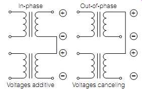
FIG. 12 Possible phase relationship of two trans former secondaries.
Turn off all applied power, and unplug the circuit. Going back to the resistance measurements performed earlier, the actual DC resistance of the transformer primaries was a very low value. For ease of calculation, assume it to have been about 12 ohms. When power was applied to the circuit, about 120 volts AC was applied to both primaries. If you used Ohm's law to calculate the primary current flow, the result would be:
I primary
E_primary
_ R_primary
__ 120 volts AC/12 ohms _ 10 amps??
Obviously, this is not correct. F1 is only a 1-amp fuse, and it would have blown instantly, if the primary current flow had been that high.
Transformers are inductors. As discussed previously, inductors try to maintain a constant current flow, by storing and releasing energy from their associated electromagnetic field. Because the 120 volts applied to the primaries is an AC voltage, the storing and releasing of energy from their electromagnetic field are a constant and continuous process. This results in the generation of a cemf (counter-electromotive force) that opposes the applied voltage and reduces the primary current flow. The opposition an inductor poses to an AC current flow is called inductive reactance. Inductive reactance will be covered further in Section 15. The sum of this reactance and the DC resistance combine to limit the primary current to a much lower level.
Just as a point of interest, I measured the AC current flow through the primary of T1 in this circuit. It was about 37 milliamps. The AC current flow through the primary of T2 should be the same. The total current flowing through the fuse (F1) would then be about 74 milliamps, or 0.074 amps.