AMAZON multi-meters discounts AMAZON oscilloscope discounts
Any bistable or two-state device can be used to count. Since a transistor has only two states-cutoff and conducting-it is a count-by-two, or binary, device. In computer circuitry, a series string of these binary devices may be reset in such a manner that one is conducting (on) at the start of each cycle.
When a pulse is applied to the input, the "on" stage is cut off.
By the coupling arrangement, this cutoff stage transfers its pulse to the second stage, thus turning it on. The next input pulse turns the second stage off and the third stage on. In this manner, the count progresses stage by stage until the final count is obtained.
Since the fundamental counter is of a binary nature and most counters must count higher than 2, some other arrangement must be made when higher counts are desired. As seen from the explanation of the stage-by-stage counter, any number of counts may be obtained, depending on the number of stages and type of coupling.
In ring counters, the output from the last stage is fed back into the first stage in order to start the counting cycle over.
A flip-Hop counter is one in which a pulse is required to turn a stage on and another to turn it off. As an example, as stage 1 is turned on, it causes its neighboring stage ( 2) to cut off (flip) and as stage 1 is pulsed off, it causes its neighboring stage ( 2) to turn on (flop). Hence the term, flip-flop.
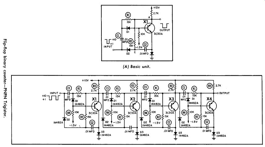
-------------- (A) Basic unit. (B) Four stage counter.
FLIP-FLOP BINARY COUNTER
A binary-counting flip-flop circuit using PNPN Trigistors is shown in Part A of the diagram. This circuit is a 2-to-l binary divider operating on negative trigger pulses. Diodes D1 and D2 act as gates; and R1, R2, C1, and C2 provide gating bias.
While the Trigistor is off, point A is at +10 volts and C2 also is charged to +10 volts, while C1 remains uncharged. Whenever a negative pulse appears at the input, D2 conducts and couples the pulse to the emitter. This causes the Trigistor to conduct.
Since C1 is uncharged, point B drops from +10 to + 1 volt. D1 remains reverse-biased and the trigger pulse is blocked from the base.
With the Trigistor on, points A, B, and C are all at +1 volt.
When the next negative input pulse occurs, D1 conducts in the forward direction, coupling the pulse to the base and thus turning off the Trigistor. Meanwhile, D2 remains reverse-biased and blocks the pulse from the emitter.
The input of this circuit is driven from the collector of an identical Trigistor flip-flop, or from the collector of an NPN silicon transistor.
A four-stage counter is shown in Part B. Since each stage re quires two pulses, sixteen are needed to produce an output. Thus, this circuit has a division of 16:1.
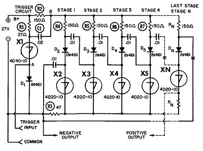
----------------- Four-layer diode ring counter.
FOUR-LAYER DIODE RING COUNTER
Here, a ring counter is shown in which four-layer transistor diodes are used as conducting stages. When DC is applied to the circuit, one of the counter stages will conduct and the other will remain cutoff. The conducting stage is furnished a holding cur rent which makes it continue to conduct. The .01-mfd capacitor between the conducting and the next higher stage ( at point A) triggers diode X1, but causes only momentary conduction since R1 does not provide a holding current. When X1 conducts, the voltage at point B drops to zero and remains there until capacitor C1 starts to charge. The loss of voltage at point B causes the counter stage to cease conducting. As C1 charges, the voltage at point B rises toward the B+ value. During this rise, the voltage of the charged coupling capacitor, added to the voltage at point B, triggers the next higher counter stage and it starts to conduct.
Therefore, each time diode X1 is triggered, the counter is advanced one stage.
DYNAQUAD DECADE COUNTER
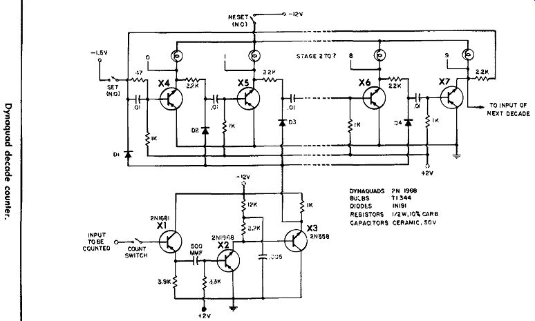
In this decade counter, the pulses to be counted are fed into an emitter follower. Here, a low-impedance, negative-going pulse is developed across the emitter resistor and capacitively coupled to the 2Nl968 Dynaquad, which is a three-terminal PNPN de vice operated as a monostable multivibrator. The eight-micro second pulses generated by the Dynaquad are coupled directly to the base of the 2N358 NPN emitter follower. The 2N358 develops eight-microsecond positive-going pulses across its 1-K load resistor. These pulses are diode- and capacitively coupled to each of the 10 Dynaquad bases. Whenever a positive pulse appears on the base of a Dynaquad, that stage is cut off. A negative going pulse is developed at its collector, which is RC coupled ( 2.2K, .01 mfd) to the base of the next Dynaquad. As a result, the latter Dynaquad is turned on. Each count, as it progresses down the line, therefore turns each successive Dynaquad on.
The tenth count is coupled back to the input, turning on the zero indicator. It is also coupled into the input circuit of the next decade, which will therefore count at one-tenth the rate of the first decade.
The reset switch interrupts the Dynaquad collector voltage, cutting off all conduction in the counter. The set switch turns on the zero-indicator Dynaquad by applying a negative voltage to its base. In the circuit shown, the resistors and capacitors limit the speed of operation to 20 khz, and lamps ( No. 334, 10 volts, 14 ma) are used as indicators.
------- CAPACITORS CERAMIC, 50V
UNIJUNCTION RING COUNTER
In this ring counter, transistor X1 conducts when no pulse is being applied to Cl. Now, assuming that X2 is conducting, C2 and C5 will both charge to some positive value. As an incoming timed pulse cuts off X1, the conduction path of X2 is opened. The charge on C2 cannot bleed off because it is blocked by the diode in the X3 circuit. Therefore, the emitter of X3 is held at a positive voltage. C5 now discharges; and as its charge appears at C2, X3 is driven into conduction.
When the cutoff pulse to the base of X1 is removed, this transistor again conducts and re-establishes the conducting path for the counter. This time, however, conduction is through X3 in stead of X2. In this manner, the count is advanced stage by stage until it reaches the output of X5 and is coupled back to X2 to start the sequence over.
BINISTOR RING COUNTER
The ring counter shown in this diagram operates with a positive input pulse to the base of transistor XL Before the trigger pulse is applied, one stage ( for example, X2) is assumed to be on while all others are off. When pulsing transistor X1 is switched on, injector current is diverted from the "on" Binistor ( X2), thus switching it off. The positive-going transient at the collector of X2 is then coupled to the base of X3. At this time transistor X1 is cut off and the injector voltage again rises to +3 volts. This combination of base pulsing and injector voltage causes X3 to conduct. The "on" state has therefore been passed along from one stage to the next at the triggering frequency. The output from this ring counter is as shown. ( See page 52). TUNNEL-DIODE RING COUNTER
In this ring counter, let us assume the first stage ( TD 1 ) is in the high-voltage state (nonconducting). Diode D1 will then be come forward-biased whenever a negative pulse is applied to its cathode. This pulse is passed to the cathode of the succeeding tunnel diode TD2, switching it to the high-voltage state. The positive transient which results at the anode is used to trigger the monostable circuit. The positive pulse from the monostable circuit is inverted and applied to the anode of tunnel diode T D1, switching it to the low-voltage state. ( See page 53).
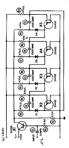
-------- Unijunction ring counter.
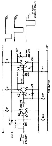
------ Binistor ring counter.
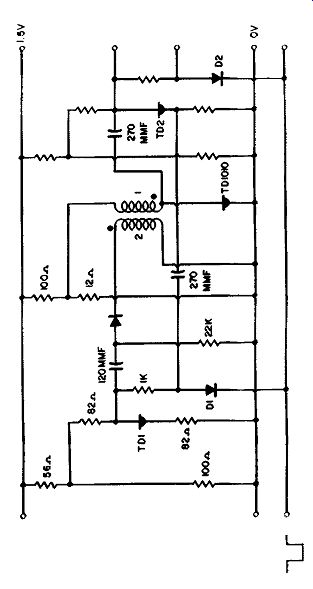
-------- Tunnel-diode ring counter.
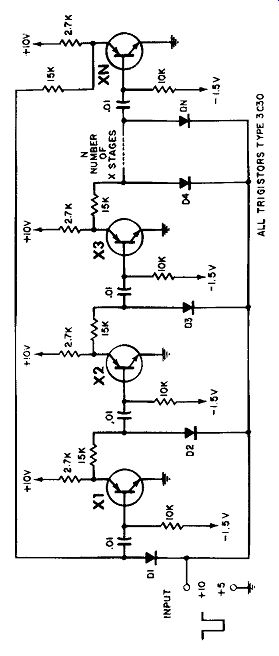
-------- Trigistor ring counter.
TRIGISTOR RING COUNTER
This circuit shows a ring counter in which only one stage is on.
For example, if X2 is conducting and a negative input pulse is applied to all base circuits through their respective diodes and capacitors, two things happen. First, the incoming pulse will drive X2 into cutoff. Second, a positive-going collector pulse from X2 will then be coupled to the base of X3 and cause that stage to conduct. In this manner, the count is advanced stage by stage until the desired final count is obtained.