A cassette player may appear in tag-along, personal, portable, boom-box, microcassette, professional, cassette/CD portable, or double cassette form, as well as in the automobile (Fig. 1). Mono sound is found in small cassette players, whereas stereo channels exist in large portables, table models, and auto cassette players. Besides play back, recording of messages and music is why cassette players are so popular.
Although many service problems are the same in most models, the larger deluxe units and car tape players have additional features. When mechanical and electronic components work side by side, trouble surfaces. Most mechanical problems can be seen or located easily, whereas the audio channels must be isolated and located with test instruments.
Required test equipment
The following equipment is needed to service cassette players:
1. Digital multimeter (DMM) or voltmeter
2. Oscilloscope
3. Audio signal generator
4. Sine- and square-wave generator
5. Capacitor tester
6. Equivalent series resistance (ESR) meter
7. External amp
8. Audio analyzer (optional)
9. Wow and flutter meter (optional)
10. Test cassettes

FIG. 1 Radio cassette players are found in portable, boom-box, and home stereo
systems and in automobiles.
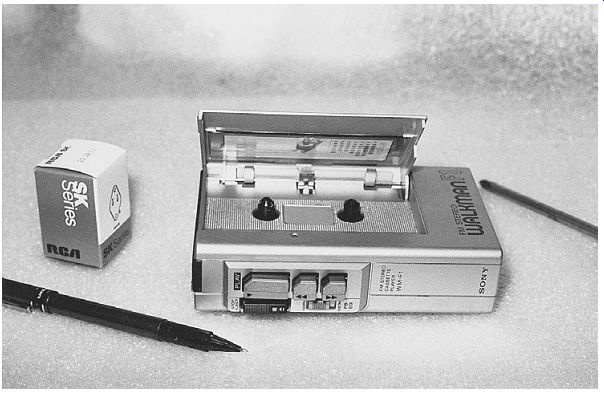
FIG. 2 A personal or tag-along cassette player is small enough to be placed
in your coat pocket.

FIG. 3 A pocket cassette can record events or live music.

FIG. 4 Besides a cassette player and radio, an auto receiver might include
a CD player.
Pocket cassette player layout
A pocket cassette player might include a tag-along for children to play their favorite music or a microcassette or professional player that can make news recordings. The small cassette player can be carried in a handbag or shirt or coat pocket for recording meetings or for gathering the latest news. A pocket cassette player can be used for fun activities or for recording professional meetings or special events (Fig. 2).
The portable cassette player
The portable cassette player may include tag-along, personal, boom-box, microcassette, and professional models. The portable cassette player is an electronic device that usually carries self-enclosed microphones for personal or professional recording. Most of the components within a portable cassette player are jammed together in a small cabinet (Fig. 3).
Auto radio/cassette player
The cassette player found in a car radio is used mostly to play music or various recordings of events. The cassette player is switched into operation as the cassette is inserted into the radio. You might find a combined cassette player and CD player in a deluxe auto receiver. A cassette player in an automobile is more difficult to ser vice than a portable cassette player (Fig. 4).
Check out that cassette
Cassette player operation may consist of music, lessons, meetings, and various event recordings. Besides music, a cassette might include test material for servicing and alignment of the cassette player. The test cassette may be used to signal trace, align azimuth, or make speed adjustments on a cassette player. The minicassette or tag along player may use a C-90 cassette.
The small C-90 cassette is quite fragile and never should be left out in the sun while in an automobile. Cassette tapes, both recorded and unrecorded, should not be stored in locations with high temperatures, high humidity, or direct sunlight. Keep cassettes away from magnetic sources such as high-powered speakers or TV sets.
A cracked cassette case should be thrown away. A defective cassette can run slow, began to drag, slow down, and pull out or "eat" tape. A worn or noisy tape should be discarded or thrown out. A defective tape may have poor recording qualities and poor frequency response. Remember that cassettes can be magnetized easily, resulting in very poor recordings in playback.
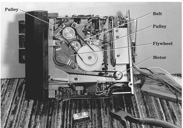
FIG. 5 Clean up all drive belts, idlers, and pulleys for slow speeds.
Slow speeds
Slow speed can result from a dry capstan bearing or pinch roller, tape wrapped around the pinch roller, a loose or oily belt, or a defective motor. Check for gummed-up or dry capstan and flywheel bearings. Simply remove the capstan, clean it with alcohol and a rag, lightly oil it with phono lube or light oil, and replace it (Fig. 5). Replace all oily, cracked, loose, or shiny belts.
Check the batteries when the tape slows down during battery operation. Try the machine using ac operation to determine if weak batteries are causing the slow speed.
Sometimes batteries left in the player too long will pull down the motor speed during ac operation. Remove the batteries and check them in a battery tester or with a DMM.
Erratic or intermittent speeds can be caused by a dirty leaf switch, belt slippage, or a clogged pinch roller. Don't overlook a defective motor when slowdown or dragging occurs. Sometimes tapping the motor while it is operating will cause it to cut up and down.
Replace a defective motor with the original part number.
Will not eject
Suspect the door latch, a defective plunger, or a loose pin when the cassette will not eject. Check for a defective eject button and no dc voltage to the solenoid plunger for no ejection of the cassette. The cassette player may not eject a tape when the door will not open because tape is wrapped around the capstan. Remove one end of a possible shorted diode across the solenoid winding, and check with the diode tester of the DMM. Poor switch contacts can cause the cassette to not eject from the player.
Readjust the cassette detector switch when a cassette is not accepted. Replace the main gear assembly when the player stops in the play mode and the cassette cannot be removed. The cassette would not eject in a Sony CFS212 player until the play lever was replaced (part number 334334201).
Dead, no sound
The dead channel might be caused by a bad off/on or leaf switch. A bad or defective cassette motor can cause a dead cassette player. A defective component in the left audio channel can cause a dead channel. Substitute another permanent magnet (PM) speaker for the suspected open voice coil in the speaker. A bad tape head can cause no playback or recording within the cassette player.
In a Sanyo M2566 cassette recorder, the sound was dead, but the motor operated with both batteries and ac power. No hum was heard when a screwdriver blade was touched to the center terminal of the volume control. Although the voltage was fairly normal on power IC1, no output signal or hum was heard. Replacing the IC1 (LA4104) power output with an SK3888 universal replacement fixed the dead portable cassette player (Fig. 6).

FIG. 6 Replace IC1 in a Sanyo M2566 cassette recorder for no sound.
Poor tape motion
Notice if the motor belt is off when there is no tape motion. Replace with a flanged motor pulley if the belt keeps coming off as the motor starts up. Replace a loose belt or broken belt when it will not stay on the capstan flywheel or motor pulley. Does the motor rotate without any tape motion? Suspect an open motor winding or a flat shaft problem with no or poor motor rotation.
A dead or defective motor can cause slow tape motion. The erratic motor rotation might result from worn brushes or tongs in a dc motor. Check the motor terminals with an ohmmeter continuity test. No continuity indicates that the motor winding is open. A defective speed circuit can cause poor or no tape motion.
Check for a dry or frozen capstan or flywheel bearing for poor tape motion. Remove the flywheel, and clean out the bronze bearings. Clean off the capstan shaft with alcohol and a cloth. Apply light grease before replacing the capstan or flywheel. Make sure that the bottom keeper plate is not bent out of line, causing the flywheel to slow down.
In a Sony FM31 cassette player, replace the motor belt and pulley if the belt keeps coming off the motor shaft.
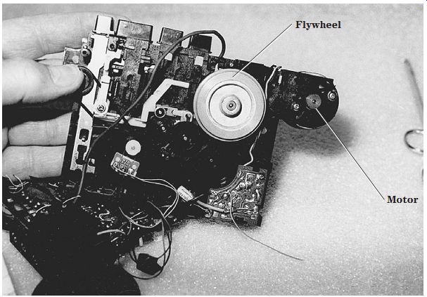
FIG. 7 Check the cassette motor, drive belt, and pulleys for no fast-forward
or rewind.
No fast-forward or rewind
Notice if the tape motor is rotating when the radio circuits are functioning with no tape motion. Check for a worn or loose belt. Check for a dirty tape or radio switch assembly with no tape movement. Excessive tightness in the gear train assembly can cause no fast-forward or rewind. Suspect a capstan motor for no fast-forward or rewind. Replace the idler pin with poor torque in fast-forward and rewind (Fig. 7).
In fast-forward operation, the fast-forward roller or idler is pressed against the take-up reel at a faster rate of speed. Check for slippage on the idler drive wheel or pulley when the tape moves slowly in fast-forward mode. A good cleanup of pulleys and rubber tires on pulleys can solve a lot of speed and fast-forward problems. A bad clutch assembly can cause poor rewind and fast-forward modes. Check for oil on the rubber drive surfaces for erratic rewind. Clean the drive areas, idlers, and pulleys with alcohol and a cleaning stick. Replace rubber tires or resurface them if the pressure roller be comes stuck.
Check for a dry spindle and idler wheel bearing for poor rewind. Suspect a missing C washer on the supply reel shaft for poor rewind. Check for a binding capstan shaft if the tape is still slow in fast-forward. Remove the capstan or flywheel, clean the bearing, and re-lube. Erratic fast-forward can be caused by a loose or oily belt and motor pulley.
A dry idler wheel or pulley can cause erratic fast-forward. Check the fast-forward speed with a torque cassette. Suspect a defective zener diode in the power supply when neither auto nor manual operation will not reverse.
Suspect a bad motor if the cassette deck has two motors, one for forward and the other for rewind. A defective high-speed motor or bad motor circuit can cause the mo tor to not rewind or fast-forward. Take critical voltage measurements with the DMM across the motor terminals when the motor torque is not up to speed or rotation. Suspect a capstan motor or Q1607 in the power supply of a Pioneer CTF1250 for no fast forward and rewind.
Tape everywhere
Check to see if the capstan or pinch roller is dirty or the take-up reel is not operating. The cassette player can "eat" or spill out tape when the take-up reel is not taking up excess tape. If the take-up reel rotates erratically or slowly, the tape can pull out. An out-of-shape pinch roller can cause the tape to spill out. Clean up the idler pulley and all tape contact surfaces in play and record modes. Replace the idler assembly if necessary; a malfunctioning one can cause insufficient tape tension and thus cause the tape to spill out.
Excess tape wrapped around the capstan drive can cause slow speeds and warbling sounds. Check for missing hub caps on the tops of the reels when there is pulling of tape. A sluggish take-up reel assembly can cause tape to pull out from the cassette.
A gear-driven idler with missing teeth or dry bearings can cause the pulling of tape.
Check for a missing washer or cam assembly for pulling of tape and loss of fast-for ward motion.
Notice if the take-up reel is not operating or erratic when tape spills out of the cassette.
Do not overlook a defective cassette. Try another one to see if it is the cassette or the tape player. If the take-up reel is operating normally, suspect a worn or uneven pinch roller. Clean the idler wheel with alcohol and a cloth. Check for any sticky substance on the capstan drive shaft. Remove all excess tape wound around the capstan and pinch roller assembly.
Jammed tape
Check for tape wrapped around the capstan when the cassette will not eject and must be pulled out of the cassette player. Try to rotate the tape backward with the capstan or flywheel. Reach in the back and locate the flywheel. Notice if the tape is loosening up as the flywheel is rotated backward. Often the cassette door will not open when there is a jammed tape in the player.
Sometimes the tape must be cut loose before the cassette can be removed. Now the cassette is damaged and should not be used again. Pull out all the loose tape from the capstan and pinch roller assembly. Make sure that all tape is removed from the pinch roller assembly or the tape will rotate slowly with clogged tape.
Clean the pinch roller assembly with alcohol and a cloth. Tape damage can result when the pinch roller is held against the capstan after the unit is turned off and may be caused by a defective zener diode in the power supply.
Squealing noises
The speaker in a cassette player may let out a loud squeal or warbling noise when the cassette function switch is pressed. A large cassette deck or player may have push buttons that operate many different functions. When the cassette switch is pressed and locked in with a loud squealing noise, suspect a dirty function switch. This switch can be a rotary or push button type that contains a stiff wire moving a flat function switch with many contacts.
Clean the function switch when there is extreme noise in the speakers. Spray cleaning fluid down in the dirty contacts, and rotate the switch back and forth to help clean the contacts. Push one button and then the cassette button to clean switch contacts. The silver contacts on sliding switches become tarnished and make poor switching contacts.

FIG. 8 Too much oil on the idlers, flywheel, and drive belt can cause slow
speeds.
Too much oil
A case of too much oil might be caused by trying to correct the speed of a cassette player by squirting too much oil on the moving parts. Excess oil found on motor, drive belt, take-up, and supply reels can destroy tape motion rather than helping. Remove all excess oil with alcohol and a cloth.
Do not oil any components within a cassette player unless the bearing is frozen or squealing. Light oil sprayed on gears, take-up reels, and plastic gears can leak down onto moving parts and can cause extra slippage (Fig. 8). All oil spots must be wiped up.
Do not apply oil or grease on top of the bearing of the capstan or flywheel if it is suspected of rotating at a slow speed. Remove the flywheel or capstan. Clean off old grease with alcohol and a rag. Apply a dab of phono or light grease at the capstan or flywheel bearing. Remount the capstan or flywheel, and wipe down the area with alcohol. Like wise, a drop of oil on the pinch roller is adequate. Wipe off oil or excess oxide on the rubber roller.
Most cassette motors do not need lubrication. They are lubricated at the factory. If one of the motor bearings begins to make a noise, a drop of light oil down into the bearing may help to stop the noise. Motors with worn bearings must be replaced.
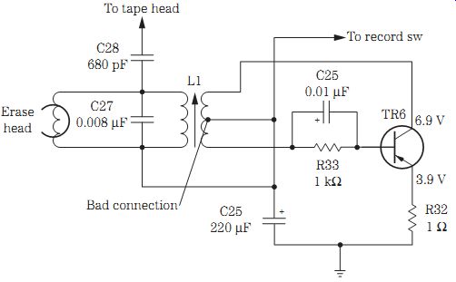
FIG. 9 Check for a bad transformer connection causing intermittent recording
in a JC Penney cassette player.
Poor erase
The erase head is designed to erase any previous recording from a tape. A jumbled or distorted recording can be caused by a packed tape erase head with excessive tape oxide. The erase head may be out of place and may not touch the tape, and this can result in a messed-up recording. In larger tape players, the erase head may be moved up into place when recording begins and may not touch the moving tape. The erase head in other tape decks is out of the way in play mode and does not pivot up into position; this can cause poor erase. A ground wire broken off an erase head will result in no erasure of a previous recording.
The erase head in a battery-operated cassette player may operate from a dc voltage source, whereas in larger tape players a bias oscillator circuit is found. A defective bias oscillator circuit can produce damaged recordings. Check the oscillator waveform at the tape head with the oscilloscope to see if the bias circuit is functioning. Take critical voltage measurements for open or intermittent transformer windings. Clean the record/play switch for intermittent or noisy recordings (Fig. 9).
Poorly soldered connections
Blobs of solder on a printed circuit (PC) board can cause intermittent operation.
Sometimes when the boards are run through a solder bath, several areas may contain excess solder. In replacing a component, the technician can apply too much solder, resulting in the shorting out of two or more traces or wiring. Extra care must be taken when replacing integrated circuits (ICs) or processors with gull-wing terminals. The PC wiring is very thin around these components.
Blobs of solder piled up at each end of a surface-mounted device (SMD) may result in a cold-soldered connection. Clean the old connection so that the SMD can lie flat, and melt solder to flow into the connection. Remember, too much soldering iron heat can destroy an SMD.
Dead left channel
Just about any electronic component from the tape head to the speaker can cause a dead left or right channel in a cassette player. A packed tape head with excess tape oxide can cause a dead or weak audio channel. Open coupling capacitors can pro duce a dead channel. Defective input transistors or ICs can cause a dead channel. If the left channel is dead in a cassette player and the AM/FM/MPX receiver is operating, check the input tape circuits for defective components. Improper voltage fed to the input transistors or ICs can cause a dead channel.

FIG. 10 Replace C412 to fix a dead left channel in a Sanyo GXT300.
The left channel was dead in a Sanyo stereo component system GXT300. The AM/FM/MPX receiver operated fine, indicating that the trouble was in the tape head in put circuits. With the volume wide open, the right channel at the tape head had a loud hum, and there was only a very low hum in the left tape head terminal. A loud hum was heard when the test probe was placed on terminal pin 1 of IC401. Tracing out from where pin 1 was located, a 3.3-uF electrolytic capacitor was tied to pin 1. Replacing C412 solved the dead left channel (Fig. 10).
Intermittent operation
Intermittent tape rotation can be caused by a loose drive belt or pulley or a dry fly wheel bearing or drive motor. A bad off and on switch can cause intermittent mo tor rotation. The motor might operate intermittently with a badly soldered connection on the pause control switch. A dirty or worn leaf switch can cause the cassette player to be intermittent. Suspect a dirty or worn function switch for intermittent cassette rotation. Look for a bad connection within the tape head to cause intermittent sound. Check for a defective automatic circuit when the cassette keeps shutting off.
Locate the left channel with the speaker or an external audio amp. Monitor the signal at the volume control to determine if the intermittent is in the front end or the output circuits. Most audio intermittents are caused by bad transistors, ICs, coupling capacitors, terminal connections, or board connections. Intermittent audio is the most difficult problem to locate and solve in the audio circuits and requires a lot of service time.
A Sharp RT1165 model would stop after a few seconds. After checking the motor and belts, a loose belt was suspected and replaced. See if the counter is turning when the tape runs. If so, you know that the belt driving the counter is now okay. Suspect the IC located behind the counter with a small magnet that rotates. Replacing the counter IC with part number VH1DN838A solved the intermittent rotation of a cassette player.
Under that magnifying glass
Sometimes it takes very sharp eyes and a lot of patience to trace out the PC wiring or cables to a given component. For instance, if one stereo channel is dead or weak and you do not know which components tie into that defective channel, start at the speaker terminals. Trace the speaker wires to a plug or soldered connection on the PC board. Since small stereo amplifiers have a speaker electrolytic coupling capacitor between the speakers and the output transistor or IC, trace it out.
By circuit tracing the PC wiring and locating large output ICs or power transistors, signal trace the defective channel with the external audio amp or scope. After locating the defective channel with IC or transistor output parts, signal trace the IC or transistors on the same side as the output component. The dead or weak channel can be compared with the normal one at several test points on the chassis. A magnifying glass and an ESR meter can help to locate broken connections, poor soldering, and cracks within the PC wiring (Fig. 11).
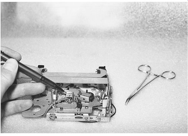
FIG. 11 Remove some boards and sections of the cassette player before locating
the defective component.
Locating and replacing bad transistors
By locating the number on the body of a transistor, you can determine what type it is, where it works, and its correct replacement by looking in the universal replacement manual (Fig. 12). Look for terminal markings on the bottom of the PC board to locate where each terminal connects. Mark each down on a separate piece of paper for reference.
Transistor styles include small, medium, and large power and special regulator types. The transistor number tells you what type of transistor it is and whether it is a low-frequency, high-frequency, field-effect transistor (FET), silicon-controlled rectifier (SCR), triac, metal-oxide semiconductor field-effect transistor (MOSFET), or opto device:
• A-The type of transistor and the number indicates the active electrical connections plus one (Fig. 13)
• B-Either Japanese (EIAJ) or American (EIA)
• C-The transistor application and if it is an NPN or PNP type
• 2N-Transistor, FET, SCR, or triac
• 2SA-Transistor, high-frequency, PNP type
• 2CB-Transistor, low-frequency, PNP type
• 2SC-Transistor, high-frequency, NPN type
• 2SD-Transistor, low-frequency, NPN type
• 2SJ-FET, P channel
• 2SK-FET, N channel
• 3SK-MOSFET, N channel
• 3N-MOSFET, dual triacs
• 4N-Opto devices
By looking at the transistor number, you can determine if it operates at a certain frequency and whether it is a PNP or NPN type. The suffix letter after the last number indicates an improvement over another transistor. Note that a B or C suffix after the number indicates a much superior transistor than the letter A.
If no numbers are found on the transistor, measure the supply voltage on the transistor, and determine what type of a circuit the transistor works in, whether it is high or low frequency, and if it is of small, medium, or large power by the size of the transistor case. Look up the data in the universal replacement manual, and replace the question able transistor. You also can look at a schematic of the same brand or a similar circuit to get the working transistor number.
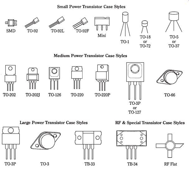
FIG. 12 Transistors appear in many different sizes and shapes.

FIG. 13 The 2SC indicates that the transistor is a high-frequency NPN type.

FIG. 14 Locate the IC by the numbers on top, and look it up in the semi conductor
manual.
Locating and replacing a bad IC
Locate a defective IC, and check the part number found on top of the IC. Look up the replacement in the universal replacement manual. Locate the input and output terminal pins. Signal trace the audio on the input terminal and then the output pin.
The signal should be much greater on the output if the IC is normal.
The top numbers and letters on the IC indicate the manufacturer, the type of de vice, whether it is American or Japanese, improvements, and package style. Most manufacturers go by the following guidelines (Fig. 14):
• A-The manufacturer of the device when registered with the Japanese or American EIA numbers (see Fig. 14)
• B-The type of device, root number, and that it is used primarily with American manufacturers
• C-Suffix letter that indicates an improvement (the letter N is superior to the letter B; the number can indicate the package style)
• C-Can or metal
• D-Dual in-line package (DIP)
• E-Flat package (SMD)
• K-TO-3 transistor package
• L-Single in-line package (SIP)
• P-Plastic package
• R-Reversed pin configuration
• S-Single in-line package (SIP)
• T-TO-220 transistor package
• V-Mounts vertically (ZIP)
Recording problems
Make sure that the cassette player is playing right before checking for recording conditions. Suspect a broken or dirty switch when the tape will play and not rewind.
A worn tape head can prevent a recording in one or both channels. A jumbled recording and no erase can result from a ground wire off the erase head. The no record symptom may be caused by a defective switching IC. Clean the record/play switch if a loud cracking noise is heard when the player is switched to record mode.
A poor or garbled recording can be caused by not properly erasing the preceding recording, and this can be caused by a metal shield that is not grounded properly. Intermittent recording can be caused by a defective function switch. Check all small electrolytics ( 5 to 10 uF) within the input circuits for intermittent recording on the ESR meter. Check all bias controls when there is intermittent recording on the left or right channel. Clean the record switch when there are intermittent recordings on the right channel. An intermittent and warbling recording sound in the right channel can result from a worn and dirty record switch.
Replace a defective erase head for no record on the left channel. A packed record tape head can cause poor or no recording. The no record and only a rush of audio in the play mode may be caused by a broken internal connection in the tape head (Fig. 15).
An extremely loud howl can result from a broken tape head connection with the volume wide open.
The packed tape head with excessive tape oxide can cause a weak recording in the right channel and no record in the left channel. Simply move the tape head with a wooden pencil or pen and notice if only a loud rush in the recording mode is caused by a broken internal tape head connection. Check for a record/play switch that is not fully engaged and needs alignment when a JC Penney 683-1795 cassette player will not record in the right channel.
In a Silver Marshall KMD-1022 cassette player, the left channel was intermittent, and the right channel was normal. Sometimes you could hear a low recording in the left channel. A loose and dirty VR101 (10-kilohm) thumbwheel control caused the intermittent left channel.
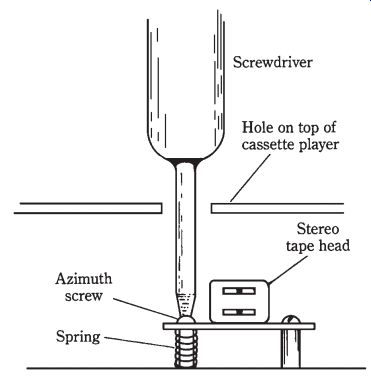
FIG. 15 Check for broken connections on the tape head or a loose screw for
poor playback and recording.

FIG. 16 Check the bias waveform with the scope at the record/playback tape
head.

FIG. 17 Check for a missing rear tab when a cassette cannot be recorded.
Suspect a defective bias oscillator circuit when there is no waveform on one side of the recording head terminal (Fig. 16). Check for voltage on the bias oscillator transistor, an open transformer winding, and no supply voltage in record mode.
ACCIDENTAL ERASE
Check the back of the cassette to see if all tabs are still intact. If the tab is knocked out of the cassette, the cassette cannot be recorded again. The record button cannot be engaged if this tab is removed. To save a recording, remove the small tab at the rear of the cassette. Place a piece of tape over the tab opening when the cassette is needed for another recording (Fig. 17).
MESSED-UP AND POOR RECORDING
When both channels produce a messed-up, garbled, or jumbled recording, suspect the erase head circuits. Clean the erase head with alcohol. Sometimes the small gap can become packed with oxide dust, which results in no recording. Try another cassette. Check that the ground wire is connected to the erase head.
Check the bias oscillator for erratic or intermittent operation with poor recording symptoms. Poor oscillator transformer connections can produce intermittent recordings. Weak recording can be caused by a dirty record head or low supply voltage to the bias oscillator. Clean the play/record switch. If both record and play are weak or distorted, check the audio output and preamp circuits. If the record time indicator will not move, suspect a broken belt or jammed assembly.
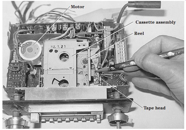
FIG. 18 A loose motor bracket or noisy motor can cause pickup hum and static
in the audio.
NOISY PLAYER OPERATION
Check the capstan or flywheel bearings, idler pulley, and motor for squeaks or screeching noises. Lubricate with a light oil. A noisy cassette hub can be checked by changing to another cassette. An open head connection can cause a loud howling in the speaker with the volume wide open. A dirty play/record button also can cause a howling noise.
When both channels have a low hum or frying noise, replace the output IC. If the noise continues with the volume turned down, suspect a noisy output IC or transistor.
When the noise can be turned down with the volume control, check the preamp transistors, ICs, and bypass capacitors. Short the base to the emitter terminal of the transistors to locate the noisy stage. Don't overlook a defective motor (Fig. 18).
A hissing noise in a cassette player can be caused by a worn or dirty function switch. Noise in the sound can be caused by a noisy motor. Replace the electrolytic across the motor terminals with one of a higher capacity (220 to 470 uF) to eliminate a noisy motor. A bad filter capacitor (470 uF) on the audio output transistor can cause a popping sound. An intermittent and noisy left channel can result from a bad output IC.
Motor boating in the sound can be caused by open decoupling and electrolytic capacitors in the voltage circuits.
NOISY RECORDING AND PLAYBACK
Suspect a broken wire on the tape head for a loud howl and rushing noise with no play or record mode. A bad internal connection of the tape head can cause the same intermittent loud and rushing noise (Fig. 19). A warbling sound and lost recording at the beginning of a tape can indicate a defective cassette. Check for a dirty or worn play/record switch when there is a loud howling sound. A squeaking noise as an idler wheel rotates indicates a dry wheel bearing. A loose motor bracket can cause a pickup hum and static in the cassette motor. In a Soundesign 5855 cassette player, the right channel was extremely noisy with the volume turned down after about 5 minutes of operation. Replacing the right output IC (STK435) repaired the noisy right channel.

FIG. 19 Check these components for noisy and frying noises in the front-end
circuits.
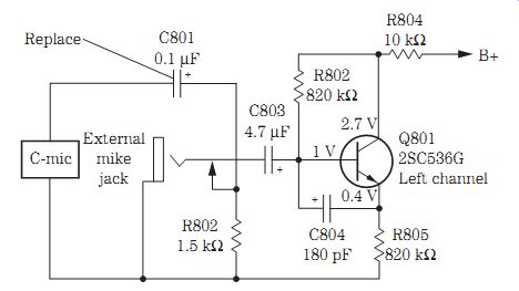
FIG. 20 Replace the C801 (0.01-uF) microphone coupling capacitor for intermittent
playback and recording.

FIG. 21 Check the cassette motor speed with a 3-kHz cassette and the frequency
meter.
INTERMITTENT RECORDING
The recording was intermittent in the left channel of a Sanyo M-X920 large portable tape player. The right channel was normal. The left channel playback of a cassette also was normal. A quick check of the C-Mic (microphone) input circuit seemed okay. When C801 (0.1 uF) was touched, the recording would cut in and out. After several hours of recording and playback, C801 was found to be intermittent and was replaced (Fig. 20).
RUN, BABY, RUN
Defective motor-regulated circuits can cause the tape to run rather fast. High-speed tape movement can result from a defective regulator circuit, a belt riding high on the motor flange of a pulley, and a defective motor. Check the cassette motor speed by inserting a 3-kHz tone cassette and connecting the frequency counter at the speaker terminals. Make sure that the belt is riding in the motor pulley groove and not on edge of pulley. Place the cassette player in play mode. Connect a 7.5-ohm resistor at the earphone jack or speaker terminals (Fig. 21).
Measure the frequency at the frequency counter. If the reading is 3 kHz, the speed is normal. A higher reading indicates faster speed, and a lower reading indicates slower speeds. If the speed is rather low, suspect belt slippage, a loose belt, or a defective motor. Oil deposits on the capstan or flywheel can produce low speeds. Check at the end of the motor to see if there is a screw speed adjustment. If not, check the motor speed regulator for a control or screwdriver adjustment. Adjust the speed on the frequency counter at 3 kHz.
The boom-box cassette player
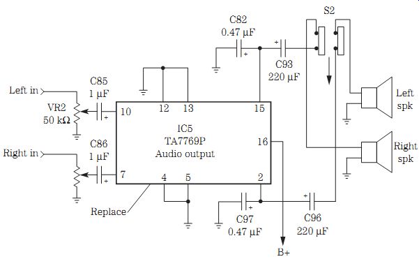
FIG. 22 Replace IC5 for a weak right and distorted left channel in a Radio
Shack 14-731 boom box cassette player.
The boom-box cassette player is found in an AM/FM/MPX radio receiver with several big output speakers. A boom-box unit is much larger in size than a portable cassette player. The boom-box player may have a double cassette deck, continuous playback, a three-band graphic equalizer, and dubbing and soft eject features. The erase head may be pivoted out of the way in playback mode and pulled into position in record mode. The boom-box player may operate on batteries or from the power line or both.
The output circuits within a Radio Shack 14-731 boom-box player have a dual IC output at 1.4 W of power. The left channel was weak and the right channel was distorted on AM/FM/MPX reception, as well as on the cassette player. This meant that the trouble was in the audio output circuits because all three signals were weak and distorted.
The radio and cassette signals were normal at the volume controls with a clipped-in external audio amplifier. The weak and distorted channels were found at output terminals 2 and 15 of IC5. Replacing IC5 (TA7769P) with the original output IC resolved the weak and distorted output symptoms (Fig. 22).
You may find different service problems within the two separate decks of a boom box cassette player. Replace the dummy erase head when deck A goes out of speed.
Check the retainer washer when the left deck capstan slides down and causes no operation in the left deck. Suspect a defective IC402 in a Sony TCW255 cassette player with no audio in the B tape deck.
MOTOR PROBLEMS
The small cassette motor is designed to operate from a battery or the ac power line. The cassette motor may be intermittent, erratic, slow, or dead. The intermittent motor may start one time and be dead the next time. Then, when the motor terminal is rotated, the motor will begin to run. Erratic motor rotation is often caused by a worn or dirty commutator. Some of these motors are almost too small to take apart, but sometimes, with patience and care, the armature and wire tongs can be cleaned (Fig. 23). At other times, you can tap the outside metal belt of the motor, and it will resume speed.
Check the motor winding with a quick RX1 resistance measurement. No or high resistance measurements indicate an open winding or a dirty commutator. Most small dc motors will have a resistance of less than 10 ohms. Check for correct voltage applied across the motor terminals with slow speeds. A small motor operating from an ac power supply may operate from 12 to 18 V, whereas in the dc battery-operated cassette player, the voltage equals the total battery voltage.
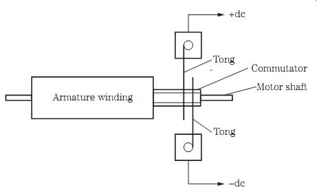
FIG. 23 Clean the commutator and tongs for motor problems.
BOOM-BOX INPUT CIRCUITS
Boom-box input circuits may consist of transistors or IC components. Most of the later players have IC parts in the entire audio circuit. In a double-deck cassette player, tape deck 1 may only play the cassette and feeds directly into the input IC circuits. Tape deck 2 is switched into the input circuits in both play and record modes.
Besides switching two different inputs into the IC, the input circuits also include switching the bias oscillator circuits in record mode.
Most problems within tape input circuits involve dirty tape heads and open or bro ken wires on the tape head. Suspect poor or intermittent switching when tape deck 2 is intermittent in play or record mode or will not play at all. Simply check the tape head continuity with the 2-kilohm scale of the DMM.
Spray cleaning fluid inside the tape head switch, and work the switch back and forth for a good cleanup. A bad record/play switch may cause intermittence and a warbling sound in one or both channels. Check tape head 1 with no playback in the right channel with tape deck 2 normal; this is caused by a ground wire off the tape head (Fig. 24).
CHECKING THE TAPE HEAD
A defective tape head may be packed with tape oxide, have an open winding or an intermittent internal connection, or be excessively worn. A worn tape head can result in a loss of high frequencies. A magnetized tape head can cause extra noise in a recording. An open head winding will produce a dead channel. Poorly soldered connections or broken internal connections can cause intermittent music. A grounded tape head winding to the outside metal shell may cause dead or weak audio.
Check the open or high-resistance head winding with the ohmmeter (Table 1).
Inspect the cable wires, and resolder for intermittent conditions. These tape head wires tend to break where the cable connects to the head winding terminals. Make sure that the tape head is engaging the tape. Check for a loose screw, which would let the head swing out of line.
The erase head is mounted ahead of the record/play head to erase any previous recording. Often the erase head has two leads and is excited by a dc voltage or by a bias oscillator circuit. Suspect the erase head when a recording is garbled or two different recordings are heard in the speakers. Measure the dc voltage across the tape head. If there is none, check the bias oscillator circuits. Simply trace the wiring from tape head to dc source or bias oscillator circuits. Check for an open erase head with the low-range (Rx10) ohm meter range (Fig. 25). The erase-head resistance can vary from 200 to 1000 ohms.
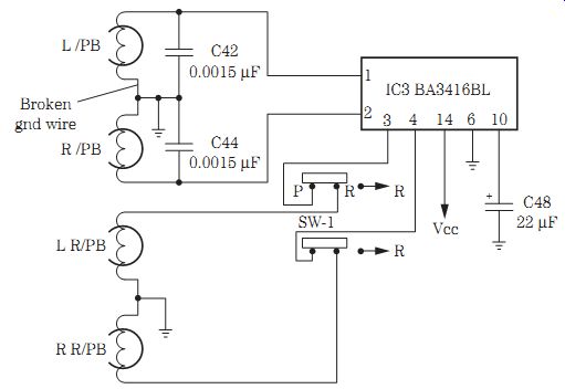
FIG. 24 Check for a torn-off ground wire on the tape head when there is no
playback in tape deck 1 of a Radio Shack SCR-55 cassette player.
=====
Table 1. Tape-head resistance of several different cassette players.
Model --- Tape-head resistance
GE-3-5808KA 225 ohms actual measurement
Panasonic RQ-L315 315 ohms actual measurement Sony M440V 348 ohms actual measurement Sony TCS 430 512 ohms actual measurement Typical R/PB tape-head resistance: 200 to 830 ohms Typical erase-head resistance: 200 ohms to 1 kilohm
=======

FIG. 25 Check the tape head for open conditions with the DMM.
MORE POWER TO YOU
In large AM/FM/MPX receiver, cassette, and CD players, the audio section may consist of high-powered transistors or IC components. The high-powered amp may have an output of 1.5 to 10 W of power delivered into tweeters and midrange and large subwoofer speakers. One large IC component may include most of the audio circuits for both right and left stereo channels (Fig. 26). Look for a large high-powered IC on a metal heat sink.
The audio from the radio, CD, and cassette player circuits is fed into an analog switch, a bass-treble board, and a high-powered IC that might include all the audio circuits. The audio output is amplified and coupled to a tweeter, subwoofer, or a very large PM speaker. Simply service the high-powered circuits as you would any audio amplifier circuits. Compare the dead or intermittent channel with the normal channel. Use the external audio amp and scope for signal tracing the signal in the audio circuits. Critical voltage and resistance measurements can weed out most defective audio amp components.
HEADPHONE CIRCUITS
The headphone jack may be connected to a separate headphone amplifier or directly from the audio output circuits of the output IC. A headphone jack may switch in the amplifier speakers when the headphone plug is removed. When the headphone plug is inserted, the speakers are disconnected. In some larger cassette players, the head phone jack may be switched into the amplifier circuits (Fig. 27).
A defective headphone jack may have dirty switching or contacts. Poor or dirty connections around the outside phone plug can cause erratic reception. Check for bro ken wires or poorly soldered joints at the back of the headphone jack for intermittent or dead sound. Intermittent sound in a Panasonic RX1940 model was caused by poorly soldered wires on the headphone terminals. Resolder the wires, and place a dab of glue on the connection to keep it intact.
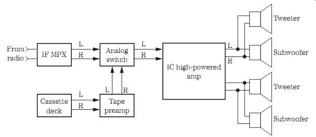
FIG. 26 Block diagram for a high-powered output IC.
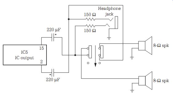
FIG. 27 When the headphone plug is inserted, the speakers are disconnected.
The auto cassette player
The auto cassette player usually is found in an automobile AM/FM/MPX receiver. Be sides the auto radio and cassette player, a CD player may be found in the same receiver. When either a cassette or a CD is inserted into the auto receiver, the radio and other player are disconnected by silent switching with silicon diodes. The AM/FM cassette receiver may have a flip-down, flip-up front panel. The AM/FM CD and cassette player may have a changer controller within the radio.
Besides a high-powered amplifier, the cassette receiver can control a CD player mounted in the trunk of the automobile (Fig. 28). A low-priced auto cassette/CD player and receiver may have from 1.2 to 10 W of output power, whereas a high-powered auto player may have from 25 to 50 W x four channels of power inside the audio system.
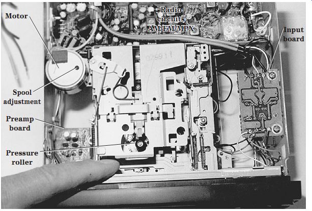
FIG. 28 Inside view of the latest low-priced cassette car receiver.
HIGH CASSETTE SPEED PROBLEMS
Excessive speeds may be caused by a defective cassette drive motor or a speed circuit. On some motors, you can adjust the speed from the rear end of the motor. Look for a small hole at the end of the motor. Also check the voltage applied to the motor terminals from the speed circuits. When the motor is running at a fast rate of speed, tap the end of the motor to see if it slows down. Replace a defective motor.
A leaky IC or transistor motor regulator circuit can cause high-speed problems. If the transistor or IC becomes open or leaky, the speed can increase or decrease de pending on the dc voltage applied to the drive motor. Try to adjust the speed control in the regulator circuits. Suspect a defective circuit when the voltage will not change during adjustment (Fig. 29).
Check the motor speed by inserting a 3-kHz test cassette in the player and connecting a frequency counter at the speaker terminals. If the tape is running higher than 3 kHz at the frequency counter, readjust the speed control within the motor speed circuits or at the rear of the motor. The tape is running slow if the meter shows a frequency below 3 kHz (Fig. 30). Try to adjust the motor speed to exactly the 3 kHz frequency.

FIG. 29 Adjust R12 to set the correct speed in a regulated cassette motor
circuit.

FIG. 30 Readjust the speed control of the motor to read 3 kHz on the frequency
meter.
AUDIO COMPARISON TESTS
Suspect a defective audio stage when one channel is weaker than the other or will not balance with the balance control. The low or weak channel can be the result of dried-up electrolytic capacitors, poor transistor junctions and ICs, and a change in bias resistors. Do not overlook a bad electrolytic shorted across the emitter resistor of an audiofrequency (AF) or input transistor for weak sound. Check for a worn balance or fader control when the audio does not balance.
Insert a 3- or 10-kHz test cassette, and notice the different amount of volume in either the left or the right channel. Start at number 1 in the audio circuit, and compare the volume in both channels. A bad or dirty tape head in either channel might cause a noisy and weak sound. Connect the external amp at spot number 2, and check for equal sound in both channels. Keep going through the audio channels until the weak stage shows up and can be located (Fig. 31).
Then check the audio on both sides of the electrolytic coupling capacitor. Check the sound on the base terminal of the AF transistor or IC to locate the weaker channel.
Take critical voltage and resistance measurements after locating the defective stage. A lower supply voltage caused by a bad electrolytic decoupling capacitor or resistor net work can cause the weaker sound stage.

FIG. 31 Compare the audio in each channel at the correct number in the tape
audio circuit.
SILENT SWITCHING
In early cassette players and receivers, the outputs of both the radio and the cassette player normally would be switched into the audio output circuits. Today, silent switching is accomplished with silicon diodes in each path of the AM/FM/MPX radio, cassette, and CD player output circuits. Often the silent switching occurs before the volume controls in the audio circuits.
Two silicon diodes are found in each audio output of an AM/FM/MPX car radio and cassette player. D101 and D102 provide signal to each 4.7-uF electrolytic coupling capacitor of the volume controls within the radio circuits. The same audio is blocked by D103 and D104 from entering the cassette motor input circuits. D103 and D104 switch the audio from the cassette player to the same 4.7- uF capacitors, and the audio cannot enter the output circuits of the stereo radio circuits that are blocked by D101 and D102.
All four diodes provide silent listening without any movement of parts (Fig. 32).
Suspect a shorted diode in the right channel of a radio when both the radio signal and cassette playback can be heard at the same time while the cassette is being played.
Check each diode with the diode tester of the DMM. You may have to remove one end of the diode for an accurate test.

FIG. 32 D101 through D104 provide silent switching in the audio circuits of
a cassette player.
ACTUAL CAR RADIO/CASSETTE PLAYER PROBLEMS
A defective volume control in a Delco 01XPB4 car radio caused the volume to cut up and down. The intermittent left and right channels of a Sanyo FT1495 were caused by a shorted volume control. The intermittent right channel of a Craig 3135 model was caused by broken foil or a broken trace at C210 coupled to the volume control. No volume was found in a Ford 5TPO model, and it was caused by an open volume control.
A loud popping sound was heard in an Automatic BTR-7284 car radio, and it was caused by a broken ground on a 500- uF electrolytic filter capacitor in the power supply.
A Delco 51CFP1 model was dead, and only a hum was heard in the speakers, caused by a leaky decoupling capacitor C102 (250 uF). Motor boating and a chirping noise were heard in the speakers of a Plymouth 6BPD model, caused by an open decoupling capacitor (1000 uF at 50-V capacity).
A loud howling sound in the left channel with no audio was found in an Audiovox C979 model, and it was caused by a red-hot IC303. A loud buzzing and mo tor-boating sound in the speakers of a Soundesign 6024 model was caused by a poor ground on the heat sink. Replace the left power output amp IC for motor boating in the left channel of a Sanyo FTV98 car radio. The power amp IC was running warm in a Kraco KID-585H model, and the sound would cut out after a few minutes of operation.
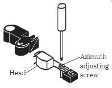
FIG. 33 Adjust the azimuth screw for a maxi mum reading on a VOM or VTVM.
HEAD AZIMUTH ADJUSTMENT
Improper adjustment of the tape head can result in distortion, muffled sound, and a loss of high frequencies. The head should be aligned horizontally for optimal sound reproduction. Check for a loose mounting screw that might cause muffled sound and a loss of audio. One side of the tape head is fastened with a small metal screw, and the other, with an adjustable spring.
Play a 10-kHz test cassette, and connect a frequency meter or volt-ohm-milliammeter (VOM) at the speaker terminals. Readjust the azimuth screw for a maxi mum reading on the meter. Likewise, a low ac voltage range on the VOM or vacuum-tube voltmeter (VTVM) can be used as an indicator. Adjust the head screw until a maximum measurement is found on the meter (Fig. 33). No highs and a muffled sound were heard in an Audiovox AV929 cassette player with a missing adjustment screw.
KEEPS REVERSING DIRECTIONS
In early car radio/cassette players, a magnetic switch would reverse the direction of the cassette motor when the tape had reached the end of the recording. With the tape coming to the end of the cassette, an automatic circuit mechanically reverses the direction of the cassette drive motor.
Some cassette players have a magnet mounted on the turntable or reel with a magnetic switch mounted below. When the tape stops rotating at the end of the recording, the magnetic switch reverses the direction of the tape and motor. Now the music is played in the reverse direction. Usually two tape heads and capstans and flywheels are found with this type of operation. Check for a broken wire on the magnetic switch when the auto reverse keeps reversing.
You also may find in early auto cassette players that the tape reversing process includes a commutator ring with spring-like tongs that ride on the commutator rings.
When the commutator stops rotating at the end of the cassette, the circuit changes the polarity of the cassette motor. Suspect dirty contacts on the commutator and tongs that cause the auto cassette to automatically keep reversing directions.
Clean the commutator rings with alcohol and a cleaning stick. Make sure that the tongs ride at the right spot on the commutator rings. When the tape was reversed in a Sanyo FT606 cassette player, no sound was heard in the right channel. Check for torn off wires on the tape head as the tape is reversed in the other direction.
WOW AND FLUTTER
Usually wow and flutter occur during playback or in recording operations. A longer duration of the sound may be called a wow condition, whereas a short change in the audio may be called a flutter sound. Uneven rotation of the tape can result in wow and flutter.
Replace the capstan and flywheel for a wow or flutter sound. A binding capstan and flywheel can cause wow and flutter in the audio. A dirty or worn belt also can cause wow or flutter. The capstan may run slowly and drag, with many rubber belt particles found on the flywheel or pulleys. A dry or bent, out-of-line flywheel can cause wow and flutter. Replace the idler spring. A worn pinch roller with a bad idler spring can cause wow and flutter. A dry reel shaft also can cause wow and flutter during playback.

FIG. 34 Wow and flutter can be checked in a cassette player with a 3- to 10-kHz
frequency variation on the frequency counter.
A motor pulley that is way out of line on the shaft can cause wow and flutter. Do not overlook a defective cassette or a bad cassette motor for uneven sound in the playback modes. Check for a defective speed circuit for wow and flutter in the audio. A loud knocking noise with a bad idler spring can cause wow and flutter.
If a wow and flutter meter is not handy, check the tape deck for wow and flutter conditions with a frequency meter and a test cassette. Connect the frequency meter to a 7.5-ohm, 10-W resistor across the speaker terminals. Insert a 3-kHz cassette into the player, and notice any deviation in frequency in the meter. If the meter changes be tween 3 and 10 kHz of the test tape on the frequency counter, the cassette player definitely has a wow and flutter condition (Fig. 34). Audio flutter during playback was caused by a dry supply reel in a Panasonic RX1822 cassette player.
For additional cassette player troubleshooting tips, see Table 2.
=========
Table 2. Cassette player troubleshooting.
[Symptom Cause Remedy]
[Cassette cannot be inserted Record button cannot N be depressed Playback button cannot T be locked in Tape does not move No sound from speakers Fast tape speed Weak or distorted sound Poor recording Poor erase ]
[ No cassette loaded.
Cassette tab removed.
Tape is completely wound
toward arrow direction.
Batteries are in backward.
Weak batteries.
No ac.
Motor doesn't work.
Headphones plugged in.
Volume is turned down.
Incorrect speed control se
Weak batteries.
Dirty heads.
Weak batteries.
Dirty R/PB tape heads.
Improper connection.
Dirty erase head.
No dc voltage.
No oscillator waveform. ]
[ Check cassette for damage.
Check for foreign material inside player.
Check if play or record button is depressed.
Load cassette.
Place tape over cutout if you want to record on this cassette.
Rewind tape with rewind button.
Fix batteries.
Test, and replace below 1.2 V.
Connect ac power adapter.
Check voltage across motor.
Continuity test motor winding to see if it is open.
Remove headphones plug.
Adjust location of volume control.
Readjust speed control.
Test, and replace below 1.2 V.
Clean heads with alcohol and cleaning stick.
Test, and replace below 1.2 V.
Clean up with alcohol and cloth.
Check all head connections.
Clean erase head.
Check dc voltage on head.
Take scope waveform on head terminals.]
===