AMAZON multi-meters discounts AMAZON oscilloscope discounts
Television makes special use of a cathode ray tube, which in turn has certain characteristics in common with a vacuum-tube (see Section 12). It has a heater, a cathode which emits electrons, an anode to which electrons are attracted, and a control grid.
Unlike a tube, however, the electrons are directed at the enlarged end of the tube or screen which is coated with a Phosphor material.
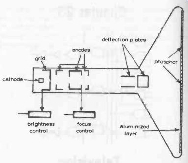
Fig. 23-1. The TV tube and its basic controls, shown in simplified form.
It is, in fact, a special type of cathode ray tube. The narrow end of the tube acts as an electron "gun," shooting electrons past the anode section.
Electrons impinging on the screen generate more electrons which are attracted back to the anode, equivalent in effect to each electron reaching the screen being bounced back to the anode. Thus no electrons, and hence no charge, actually collects on the screen. Meantime, however, each electron reaching the screen makes the phosphor glow, which glow persists for a short period after the electron has been "bounced back." The brightness of the glow produced is dependent on the type of phosphor (which also governs the color of the glow), and the strength of bombardment of electrons. The latter is controlled by the bias voltage applied to the grid. In other words, grid bias adjustment is the brightness control on a TV tube, Fig. 23-1. The actual brightness is also enhanced by an extremely thin layer of aluminum deposited over the phosphor to act rather like an outward-facing mirror, but transparent from the other side as far as electrons are concerned.
To produce a picture from electron bombardment, two other controls are necessary. The first is a means of deflecting the electron beam so that a single spot can trace out a particular path covering all the variations in picture density over the whole screen area. The second is a means of focusing the electron beam into a tiny spot so that the traced picture is sharp, not fuzzy.
Deflection is achieved by directing the stream of electrons through two sets of parallel coils set at right angles to each other like the X and Y deflection plates in a simple cathode ray tube (Section 12). Signal voltages applied to the X-coils will deflect the beam sideways; signal voltages applied to the Y-coils will deflect the beam vertically. Combined X and Y signals will thus direct the beam toward any spot on the screen, depending on the resultant effect of the two signals.
Focusing, meantime, is achieved by using supplementary cylindrical anodes arranged to work as an electronic lens, with the focusing effect adjustable by varying the voltage applied to one (or more) of these anodes.
These anodes come before the deflection plates, i.e., in the parallel or "gun" section of the tube rather than in the divergent section.
Electronic circuits can respond very rapidly -- which is how television can be made to work at all! To "paint" a picture on the screen a spot of light (produced by a focused electron beam) has to traverse the whole picture area, zig-zag fashion, at least 30 times per second if the picture is to appear reasonably free of flicker. It does this in a number of parallel lines, usually running from left to right, with rapid "flyback" between lines, Fig. 23-2.
The greater the number of lines the clearer the picture will be, i.e., the better the definition. The standard commonly adopted is 525 lines (per picture). So the actual frequency at which lines appear, called the line frequency, is 30 x 525 = 15750 per second. This line pattern is known as a raster. The lines making up the raster can actually be seen if you examine the television screen close up, or turn up the brightness control when no picture is being transmitted. Only the parallel lines will be seen in the raster. During flyback, the cathode ray tube is cut off and no lines appear on the screen.
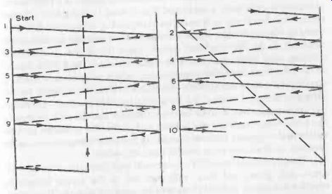
Fig. 23-2. Illustrating the formation of a raster. First the odd number lines
are scanned from left to right (solid lines) with flyback between each line
(dashed lines). Downward movement is controlled by the time base.
After scanning half the picture lines, the time base flies back to the top. All the even number lines are then scanned, with "flyback" between each line (right hand diagram).
At the end of the last line the time base flies back to top left to start the sequence all over again. These two diagrams superimposed would represent a complete raster.
In practice the picture is scanned 60 times per second, not 30.
This is fast enough to eliminate any trace of flicker, but using an optical "trick," the actual picture frequency is still only 30 per second. Scanning takes place in two stages--first the odd lines only, then the even lines. Each scan therefore builds up only half the picture, the two halves following each other to present the complete picture.
Movement of the lines downwards is accomplished by the time base circuit starting with the first (odd) line and restarting a line at the left two positions down each time. This continues until the scanning has reached 525 ÷ 2 = 262% lines. The spot then flies back to the top again, starting half way along the first even line and repeats the process to scan the 262% even lines which make up the second half of the picture. This process is known as interlacing. Actually a few lines get left out in this changeover process, but this does not show up on the picture.
Picture transmission and picture reception operate in reverse mode.
The television camera scans the scene to be transmitted in 525 lines at a picture frequency of 30 per second, and turns the light spot response into electrical signals. The number of lines has been quoted as governing picture definition, but this is not the whole story.
A scan of 525 lines gives good picture definition from top to bottom, e.g., the picture is built up top-to-bottom from 525 "strips." There is also the question of how many individual picture elements are covered by each strip. The answer is about 600 as an absolute minimum for good picture definition side-to-side, or the equivalent of 600 phosphor "dots" making up each line. The total number of individual "dots" or picture elements in each whole picture trace is thus 315, 000. Since the picture frequency is 30 times per second, this calls for a transmitted signal frequency of 2.5 MHz.
These "intelligence" signals are broadcast like any other radio trans mission-superimposed on a carrier wave to produce a modulated signal which can be picked up by a receiver and decoded on a similar principle to ordinary radio reception, except that the decoder now has to handle radio frequencies of 2.5 MHz and not of signals, so the TV receiver decoder is considerably more complicated than a radio receiver detector.
There is also another important difference. Carrier wave frequencies have to be much higher than modulation frequencies for satisfactory results. Hence the frequency of television picture signals is in the VHF range.
It is invariably an AM broadcast with sidebands, operating within a channel width of 8 MHz. Either AM or FM can be used for the accompanying sound signal, FM being standard.
The fairly wide channel width or frequency spread occupied by a television transmission does not make it susceptible to receiving spurious signals upsetting the picture (but not the sound, which is operating in a narrow band like any ordinary FM receiver). It also limits the number of television stations that can be accommodated in the VHF band without interfering with each other.
This particular consideration also makes the design of a color television system even more complicated than it need be using first -principle electronics. For example, it would mean expanding the bandwidth to three times its black-and-white figure to transmit three separate pictures simultaneously in the three primary colors. Since this is not an acceptable solution, color information has to be contained within the 8 MHz channel allowed for black-and-white transmissions, which becomes an extremely complicated subject and virtually impossible to describe in simple terms.
Strangely enough, however, it does simplify ne other problem-the essential requirement that a color television should also be able to receive black-and-white transmissions in black and white. The broadcast stations still have the opposite problem of ensuring that color transmissions can be received on black-and-white sets in black-and-white! The conventional color TV tube is made with three guns, one for each color-red, green, and blue; with each dot on the screen formed by separate red, green, and blue phosphors arranged in a triangle. The picture is thus scanned by a triangle of beams converging on each triangle of dots at the same rate as in a black-and-white picture. The resulting sharpness of the color picture depends primarily on the accuracy of convergence, and on some tubes may vary noticeably from center to edge and/or top to bottom.
This may be a limitation of that particular design of tube and associated circuitry, or merely a matter of convergence adjustment (which is usually factory-set and can be quite complex).
There are improvements in this respect in the case of some modern tubes, e.g., simplifying convergence problems by using in -line guns and color spots.