AMAZON multi-meters discounts AMAZON oscilloscope discounts
Radio broadcasts consist of a radio frequency (rf) signal generated at a specific frequency allocated to a particular station, on which is superimposed an audio frequency (aft signal.
Only rf will work for transmission. The of part, which is the actual sound content of the signal is, almost literally, carried on the back of the rf signal, the two together forming what is called a modulated signal.
This combined signal can be produced in two different ways--amplitude, or up-and-down modulation, known as AM; and frequency modulation (actually a very small variation in rf signal frequency about its station frequency), known as FM.
AM is the simpler technique and is widely used for long wave, medium wave and short wave broadcasts. Broadcasting has always been referred to in terms of wavelengths instead of signal frequency, until comparatively recently. The relationship between wavelength and frequency is:
wavelengths (meters) -frequency, Hz
300, 000
300,000 frequency, Hz = wavelength, meters
(The figure 300,000 is the speed of light in meters/sec., which is the speed at which radio frequency waves travel.)
In the case of FM, very high transmitting frequencies are used - and it is generally referred to as VHF (very high frequency). Actual wavelengths are very short, and so it is much more convenient to speak of frequency, the usual range for FM broadcasts being 90-100 million Hertz (90-100 MHz). A simple calculation will show that this means a wavelength of about 3.2 to 2.9 meters or say 3 meters.
Regardless of whether the broadcast is AM or FM, though, any radio frequency signal has the same basic requirement for receiving it. The presence of this signal has to be "found" and then sorted out from signals from other broadcast stations. The "finding" device is the aerial, and the "sorting out" device is the tuned circuit, which together form the front end of a radio receiver as shown in Fig. 22-1 (the extreme left-hand part of a circuit diagram--see also Section 19).
A tuned circuit consists, basically, of a coil and variable capacitor, which can be adjusted to show resonance or maximum response to a particular signal frequency applied to it. A full explanation of this behavior is given in Section 7. All the broadcast signals reaching the tuned circuit are very, very weak. Only that signal to which it is tuned is magnified by resonance, so that it stands out at a very much higher level of signal strength.
An actual aerial wire connected to the tuned circuit may or may not be necessary. In the case of AM reception, the coil winding will also act as an efficient aerial wire, if wound on a ferrite rod. This dispenses with the need for an external aerial. The only disadvantage is that the tuned circuit will be directional, minimum signal strength being received when the ferrite rod is pointing towards the transmitter sending the signal, and maximum signal strength when the ferrite rod is at right angles to this direction. This effect is most noticeable on small radio receivers which have only moderate amplification. To receive certain stations at good listening level, even with maximum adjustment of volume, it may be necessary to adjust the position of the set. Larger receivers normally have enough amplification to compensate for this, but the effect can still be quite noticeable. Also, it is always best to operate a receiver below maximum amplification because this minimizes distortion of the signal.
-------------
aerial; coupling capacitor to minimize effect of aerial capacitance on tuned circuit; Coil; variable capacitor; tuning capacitor; foil wound ferrite to rod
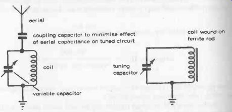
Fig. 22-1. A variable capacitor and coil form the usual tuned circuit. Strictly
speaking this tunes the aerial, if an external aerial wire is used. Most AM
receivers use a ferrite rod aerial which does not require an external aerial.
The FM receiver does need an external aerial because a wound coil or a ferrite rod aerial just will not work at this rf. For satisfactory results, this external aerial also needs to be a special type, known as a dipole, which itself is "tuned" by making its length one half of the signal wavelength. The latter may vary from 11.5 ft. to 9.5 ft. in the 90-100 MHz FM band, so a mean wavelength figure of about 10 feet is adopted, giving a realistic dipole length of 5 feet.
The three practical FM aerial forms are a vertical telescopic aerial extending to 30 in. ; a horizontal wire (or rod aerial) with 30 in. "legs"; or a folded dipole, as shown in Fig. 22-2.
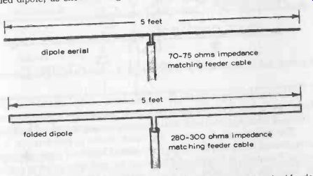
Fig. 22-2. FM aerials need connecting to the set via a correctly matched feeder
cable. --- 5 feet dipole aerial 5 feet 70-75 ohms impedance matching feeder
cable folded dipole 280-300 ohms impedance matching feeder cable ---
DETECTION
The tuned circuit is much simpler than the foregoing descriptions may appear to imply.
It is really a matter of getting the component values right, and working with high efficiency (see also Section 6 and Q-factor). Design of the tuned circuit is a little more complicated when a radio is intended to receive more than one waveband. Even an AM receiver needs separate aerial coils (or at least separated wings on a single ferrite rod) to cover long wave, medium wave, and short wave. So the tuned circuit design for an AM receiver could involve three or more tuned circuits selectable by a switch.
In the case of an FM receiver (or the tuning circuit for the FM section of a multi-band receiver), there is really no practical form of wound aerial coil which can be used (a theoretical coil of this type would probably require only a part of a single turn). So the starting point is a dipole aerial.
This itself is a tuned circuit (i.e., designed to be resonant with the mean frequency to be covered in the FM band), but its amplification of signal will not be anything like as good as that of the coil-and-capacitor tuned circuit of an AM receiver.
To compensate for this, the FM receiver normally uses an amplifier stage immediately following the aerial, known as a preamplifier or RF amplifier (because it is an amplifier of signals at radio frequency). This amplified signal is fed to the next stage of the receiver via a tuned output,. typical circuit of this type being shown in Fig. 22-3.
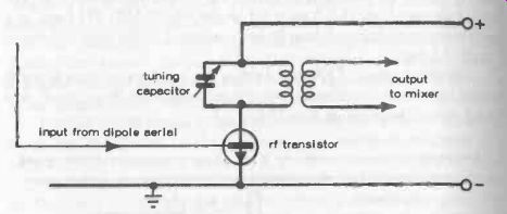
Fig. 22-3. Basic rf amplifier (or preamplifier) circuit as used in most FM
receivers. --- tuning capacitor; Input from dipole aerial; output to mixer;
rf transistor ---
The detector stage following the tuned circuit can be extremely simple.
In the case of AM, it only needs to be a diode connected to a potentiometer as its load. This potentiometer also acts as the volume control -- Fig. 22-4.
The signal passed on from the tuned circuit to the detector is a strengthened version of the original modulated broadcast signal. In other words, it contains both AF and rf. The rf part has now done its job in getting the signal into the tuned circuit. Now it needs to be removed, which can be done by rectifying the signal. A diode does this job by "chopping off" one half of the rf signal so that the output from the diode consists of half-cycles of rf. These half cycles have the AF content of the signal still imposed, so the next requirement is to filter out the rf part to turn the output into an undulating dc signal. These undulations follow exactly the same variations as the AF signal originally imposed on the transmitter rf signal at the transmitting station by a microphone, or recording.
As explained in Section 6, a resistor and capacitor can act as a filter for any specific frequency required. Thus the diode detector is associated with a matching load (resistance) and associated capacitor forming the required filter circuit, e.g. see Fig. 22-4 -- so that only varying dc is passed at output from the detector stage. It is usually coupled to the next stage by a capacitor, which has the further effect of balancing the varying dc signal about its zero line (i.e., giving it positive and negative values, rather than "all positive values").
In practice, the output load (R in Fig. 22-4) is usually a variable resistor, which component then also acts as a volume control. The fact that this is followed by a coupling capacitor also avoids any flow of dc through the moving contact (wiper) of this control and reduces any tendency to reproduce "noise" by movement of this control.
The aim in selecting the detector circuit components is that the signal passed by the diode is exactly the same as the original signal generated by the studio microphone (with certain losses and possible distortions!).
Fed to a microphone working in reverse (i.e., headphones or a loudspeaker) they would be heard as the original speech or music, etc.
But the signals at this stage are still too weak to have enough power to drive headphones or a loudspeaker, so the next step is to amplify the AF signal passed by the detector.
rf + of signal ; capacitor to filter cut residual if on superhets ; coupling capacitor helps to eliminate 'noise' from volume control II
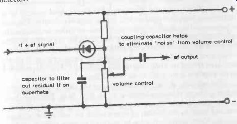
Fig.
22-4. Basic AM detector circuit.
volume control AF output
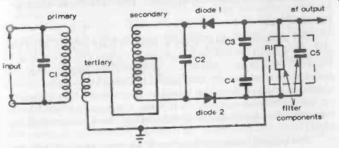
Fig. 22-5. Basic FM detector circuit.
FM DETECTOR
In the case of an FM receiver, the detector is a little more complicated.
It has to detect how the frequency of the signal is varying, not its amplitude, so it has to extract the original frequency as well as apply rectification.
FM receivers invariably work on the superhet principle, so the frequency to be extracted is the intermediate frequency or i-f. A basic detector circuit employs a three -winding transformer with primary and secondary tuned to the intermediate frequency (by capacitors C1 and C2 in Fig. 22-5). The third winding injects a voltage into the secondary circuit, each leg of which carries a diode, D1 and D2, associated with a capacitor C3 and C4.
The working of this circuit is to detect variations in signal frequency in terms of an AF output, so that the final output is exactly the same, in terms of signal content, as that from an AM detector. Thus it can be dealt with in the same way. The additional components R1 and C5 shown on the diagram are to suppress unwanted signals which may be present after detection.
AMPLIFIER STAGES
A single transistor can provide amplification of signal strength up to 100 times or more (see Section 9 for typical amplifier circuits). The main requirement of the amplifier following the detector is that the transistor be specifically suitable for amplifying AF (when it can act as a further block to any residual RF remaining in the input signal to the amplifier). Ideally, there should be no rf signal present at the input to the amplifier stage (it should have been filtered out in the detector stage), since any rf voltage presented to the amplifier stage could cause overloading.
Theoretically, at least, any amount of amplification can be produced by adding additional transistor-amplifier stages (Fig. 22-6). This does, however, greatly increase the chances of distorting the signal, so there are practical limits to the number of stages which are acceptable in simple circuits. Much better results can be produced by more sophisticated circuits, particularly the superhet (see below), where first some intermediate signal is amplified before detection; and subsequently amplified again after detection.
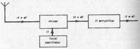
Fig. 22-6. Adding amplifier stages is not necessarily a good thing for amplifying
an AF signal as each stage can amplify distortion produced in the previous
stage.
OUTPUT STAGE
The AF amplifier output (or last AF amplifier stage output if more than one stage is used) can develop enough power to drive a loudspeaker, as in Fig. 22-6, although there may be some problem in matching the (amplifier) output to the (loudspeaker) input, particularly using low .to medium power transistors which require a high impedance load to match. Most loudspeakers have a load impedance of only 4-16 ohms. A basic solution here is to use an output transformer to match the different load characteristics, as in 22-7.
----------
AF signal input; impedance matching transformer; coupling capacitor; output transistor; class A amplifier
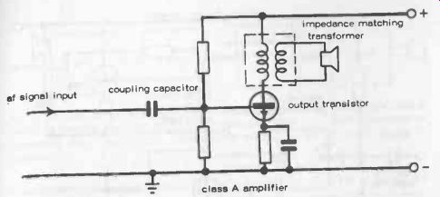
Fig. 22-7. Basic Class A output circuit.
--------------
This relatively simple solution does, however, have one particular limitation (for the more technically minded, it is called a Class A output). It is relatively inefficient and so draws a high current in providing a suitable listening level from the loudspeaker.
It is satisfactory for use in car radios, but represents too heavy a current drain for most other battery-powered receivers.
These normally use a Class B output circuit where the last amplifier transistor drives a pair of transistors which effectively work in a push-pull circuit operating the loudspeaker.
The output power obtained is consider ably more than double the power available from a single transistor; also, and output transformer is not necessary.
Most modern AF amplifiers for radios end up in a push-pull output stage of this type, like the circuit shown in Fig. 22-8.
The limitations of simple radio receivers are mainly connected with the limitation of a detector. A detector is most effective working with an rf input voltage of 1 volt or more.
Signals derived directly from an aerial circuit are seldom more than a few millivolts in strength, and the weaker the signal the less effectively they will be detected in any case.
In other words, the range of stations that can be picked up is limited, and no amount of amplification after detection can make up for this limitation.
This limitation, or lack of sensitivity can be overcome by amplifying the incoming signal before detection, so that the detector is always working with good signal strength. This can be done by rf amplification of the aerial signal by introducing an amplifier stage right at the beginning of the circuit as in the FM receiver (Fig. 22-3); or by the superhet working.
The latter also improves the selectivity of a receiver, or its ability to tune in sharply to wanted signals and reject nearby station signals.
THE SUPERHET
Having arrived at a standardized output stage, it is equally true to say that nearly all modern radio receivers are of the superhet type, which is considerably more complicated than the circuit traced through above. The whole "front end" works on an entirely different principle.
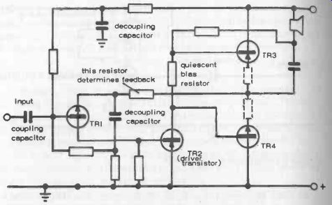
Fig. 22-8. Basic Class B output circuit. TR1 works as a preamplifier. TR2
is the driver. TR3 and TR4 are a complementary pair of transistors, working
alternatively in "push-pull." The two resistors shown by dashed lines
may be added to improve the stability of the circuit. These only need to be
of very low value (e.g., 1 ohm).
Starting point is the tuned circuit (ferrite rod aerial) in the case of an AM receiver; or a dipole aerial feeding an rf amplifier in the case of an FM receiver (the latter amplifying the modulated radio signal in conjunction with a tuned resonant circuit). In both cases the boosted tuned signal is fed to an oscillator-mixer.
This is a two-function circuit, although its duty is usually performed by a single transistor associated with a tuned oscillator circuit. This tuned circuit is mechanically coupled to the aerial tuning in the form of a ganged capacitor (i.e., two separate variable capacitors coupled, or "ganged" to move together when the tuning control is adjusted), so that it "tracks" the aerial circuit tuning while remaining separated from it by a constant frequency. This difference is known as the intermediate frequency or i-f, and is usually 455 kHz above the aerial frequency (it can have other values in certain sets ; and can also be below rather than above the aerial frequency).
The oscillator part of the oscillator-mixer is concerned with generating this fixed intermediate frequency, tracking exactly above (or below) the signal frequency to which the aerial circuit is tuned. The two signals are combined in the mixer part of the oscillator-mixer, which also has a fixed tuned circuit (actually the primary side of a' transformer associated with a capacitor) which responds only to the intermediate frequency - Fig. 22-9.
This i-f signal also now has the same AF modulation as the original signal. In other words, it is a duplicate of the wanted AF signal, but at this stage superimposed on a fixed intermediate frequency.
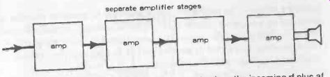
Fig. 22-9. Front end of a superhet receiver, showing how the incoming rf plus
AF signal is transformed into an AF signal now imposed on a fixed intermediate
frequency (i-f).
This makes amplification without distortion more simple to achieve.
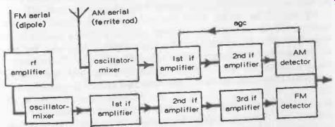
Fig. 22-10. Basic design of an AM/FM receiver shown in block form. The only
common circuit is an AF amplifier (usually a Class B output) following the
detectors.
There are a number of technical advantages to this seemingly un necessary complication of incoming signal treatment. First, the process of super-heterodyning gives much better selectivity or rejection of unwanted signals. Then, the signal output from the mixer is at a constant frequency, making it easy to amplify with the further possibility of eliminating any remaining unwanted frequencies since an i-f amplifier has fixed-and virtually exact-tuning.
In practice, i-f amplification is usually carried out in two stages (AM receivers) or three stages (FM receivers).
The detector then follows after the i-f amplifier stages--Fig. 22-10. Each i-f amplifier stage consists of a tuned transformer, adjustment of tuning being done by an iron dust core in the transformer coil former. Once correctly adjusted, in setting up the receiver for proper working, no further adjustment is necessary, or made.
The cores are sealed in this position.
The remainder of the radio circuit follows as before--rf amplifier stage(s) following the detector, terminating in (usually) a push-pull output stage. But there is just one further refinement which can be added. By feeding a proportion of the signal passed by the detector back to the first i-f amplifier stage, automatic volume control (normally called automatic gain control or agc) can be achieved.
If the signal strength passed by the detector starts to rise to a point where it could become distorted, then feedback via the agc line automatically reduces the amount of signal entering at this point, so maintaining the detector working under optimum conditions.
Agc applies only to the control of amplification of signal in the i-f amplifier stages. The output or gain of the final i-f amplifier stage(s) is governed by a separate volume control (potentiometer), typically located before the first of amplifier stage. This potentiometer, incidentally, usually has a capacitor connected in parallel with it to filter out any residual i-f which may have got past the detector.