AMAZON multi-meters discounts AMAZON oscilloscope discounts
Resistors, as their name implies, are designed to provide some desirable, or necessary, amount of resistance to current flow in a circuit. They can also be used to "drop" voltages, as explained in Section 3. As such, they are the main elements used in circuit design to arrive at the desired current flows and voltages which work the circuit. Resistors do not generate electrical energy, but merely absorb it, which is dissipated in the form of heat. The performance of a resistor is not affected by frequency, so it behaves in the same way in both dc and ac circuits. (There are exceptions, as noted later.) Resistors are specified by (a) resistance value in ohms; (b) tolerance as a percentage of the nominal value; and (c) power rating in watts. They are also categorized by the type of construction.
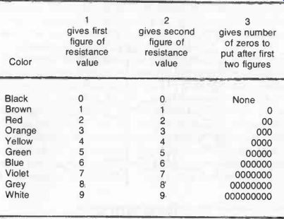
Table 4-1. Universally adopted color coding. Example: resistor color code
read as brown, blue, orange.
COLOR CODE
Resistance value and tolerance is normally indicated by a color code consisting of four colored rings, starting at, or close to, one end; see Fig. 4-1. These are read as follows:
1st ring gives first digit
2nd ring gives second digit
3rd ring gives number of zeros to put after first two digits.
The fourth colored ring gives the tolerance:
silver -10% tolerance either side of the nominal value
gold -5% tolerance either side of the nominal value
red -2% tolerance either side of the nominal value
brown -1% tolerance either side of the nominal value
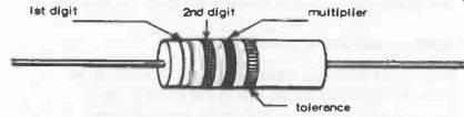
Fig. 4-1. Standard resistor color code marking.
Absence of a fourth ring implies a tolerance of 20%.
Certain types of modern resistors of larger physical size may have letters and numbers marked on the body instead of colored rings. With this coding, the numbers indicate the numerical value and the following letter the multiplier, where:
E = x 1 K = x 1,000 (or kilohms) x 1,000,000 (or megohms)
A second letter then gives the tolerance:
M = 20% tolerance either side of the nominal value K = 10% tolerance either side of the nominal value
j = 5% tolerance either side of the nominal value H = 2.5% tolerance either side of the nominal value G = 2% tolerance either side of the nominal value F = 1% tolerance either side of the nominal value The actual range of (nominal) resistance values to which resistors are made is based on steps which give an approximately constant percentage change in resistance from one value to the next -not simple arithmetical steps like 1, 2, 3, etc.
These are based on the preferred numbers:
1, 1.2, 1.5, 1.8, 2.2, 2.7, 3.3, 3.9, 4.7, 5.6, 6.8, 8.2, 10, 12, 15, 18, etc.
Thus, for example, a typical range of resistor values would be:
10, 12, 15, 18, 22, 27, 33, 39, 47, 56, 68, 82, and 100 ohms; 120, 150, 180, 220, 270, 330, 390, 470, 560, 680 and 820 ohms; 1, 1.2, 1.5, 1.8, 2.2, 2.7, 3.3, 4.7, 5.6, 6.8, and 8.2 kilohms; 10, 12, etc., kilohms; 1, 1.2, etc., megohms.
As regards tolerances, as a general rule, resistors with a 10 percent tolerance are suitable for average circuit use. The actual resistance value of, say, a 1 kilohm resistor would then be anything between 900 and 1,000 ohms. For more critical work, such as radio circuits, resistors with a 5 percent tolerance would be preferred. Closer tolerances are not normally required, except for very critical circuits.
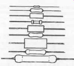
Fig. 4-2. Examples of modem resistor outlines (actual size).
POWER RATING
The physical size (or shape) of a resistor provides no clue to its resistance value, but can be a rough guide to its power rating. Physical sizes (Fig. 4-2) range from about 4mm long by 1mm diameter up to about 50mm long and 6mm or more diameter. The former would probably have a power rating of 1/20th watt and the latter possibly 10 watts. More specifically, however, the power rating is related to type as well as size. A general rule which does apply to power rating, however, is that while this figure nominally represents a safe maximum which the resistor can tolerate without damage, it is usually best to operate a resistor well below its power rating -say at 50 percent rating -particularly if components are crowded on a circuit, or the circuit is enclosed in a case with little or no ventilation.
VOLTAGE RATING
Maximum operating voltage may also be specified for resistors, but since this is usually of the order of 250 volts or more, this parameter is not Important when choosing resistors for battery circuits. Resistors used on mains circuits must, however, have a suitable voltage rating.
Types of Construction
Resistor types classified by construction are:
1. Carbon (also called carbon-composition, molded-carbon, and car bon rod). These are in the form of a small rod molded from carbon and a binder, with wire connections at each end. The rod is usually protected with a paper or ceramic sleeve, or a lacquer coating. These are the most common (and cheapest) type of resistor, generally available in values from 10 ohms to 22 megohms. Standard types are usually available in 1/8, 1/4, 1/2, 1, and 2 watt ratings.
It is a general characteristic of carbon resistors that their value re mains stable at normal temperatures, but above 60° C their resistance increases rapidly with increasing temperature.
2. Carbon -film Resistors (also known as high -stability carbon resistors). These are manufactured by depositing a thin film of carbon on a small ceramic rod. The rod is fitted with metal end caps, to which wire leads are attached. The body of the resistor is usually protected by a varnish, paint or silicone resin coating, but some types may be encased in a ceramic, plastic or glass outer coating.
Carbon-film resistors are little affected by temperature changes (their stability is usually better than 1 percent) and are also characterized by low noise. They are available in sub-miniature sizes (1/20 and 1/10 watt power rating), and in larger sizes up to 1 watt power rating. They are a preferred type for radio circuits, particularly as they have excellent high -frequency characteristics.
3. Metal-film Resistors. These are made by depositing a metallic film (usually nickel -chromium) on a glass or ceramic rod. A helical track is then cut in the film to produce the required resistance value. Metallic end caps are then fitted, carrying the wire leads, and the body protected by a lacquer, paint, or plastic coating. Stability characteristics are similar to those of carbon -film resistors, but they are more expensive. They are generally produced in miniature sizes with power ratings from 1/10 watt upwards.
4. Metal-oxide Film Resistors. Construction is similar to that of a metal-film resistor except that the coating used is a metallic oxide (usually tin oxide), subsequently covered with a heat-resistant coating. This type of resistor is virtually proof against accidental overheating (e.g., when making soldered connections) and is also not affected by damp. Stability is very high (better than 1 percent), and the power ratings are high for their physical size.
5. Metal-glaze Resistors.
In this type, the resistive film deposited on the rod is a cermet (metal-ceramic), otherwise, construction is similar to metal-film resistors.
Film -resistors may also be classified as thick -film or thin-film. As a general rule, individual resistors of this type are thick -film. Thick -film resistors are also made in groups on a small substrate and encapsulated in integrated circuit "chips." Thin-film resistors are made in a similar way, but on a considerably smaller scale for use in the manufacture of integrated circuits.
Effect of Age
All resistors can be expected to undergo a change in resistance with age. This is most marked in the case of carbon-composition resistors where the change may be as much as 20 percent in a year or so.
In the case of carbon-film and metallic-film resistors, the change is seldom likely to be more than a few percent.
Effect of High Frequencies
The general effect of increasing frequency in ac circuits is to decrease the apparent value of the resistor, and the higher the resistor value the greater this change is likely to be. This effect is most marked with carbon-composition and wire-round resistors (see below).
Carbon-film and metal-film resistors all have stable high -frequency characteristics.
WIRE-WOUND RESISTORS
Wire-round resistors are made by wrapping a length of resistance wire around a ceramic coil. The whole is then covered with a protective coating or film. The specific advantages offered by wire resistors are that a wide range of values can be produced (typically from 1 ohm to 300 kilohms) with Power ratings from 1 to 50 watts (or up to 225 watts in "power" types), with tolerances as close as 1 percent. They also have excellent stability and low noise. Their disadvantages are that they are most costly and also unsuitable for use in ac circuits carrying high frequencies because their effective value changes. Physically, they need be no bigger than film-type resistors for the same power rating.
VARIABLE RESISTORS
Variable resistors consist of a resistive track swept by a wiper arm. The position of the wiper arm determines the length of track in circuit, and thus the actual resistance present. The track may be circular (usually a 270° arc) or in a straight line, circular types being the more common. Both types are known as potentiometers or pots.
The resistive element may be wire-wound, carbon-composition, carbon-film, or metallic-film. The former type is known as a wire-wound potentiometer. Carbon-track potentiometers are the cheapest (with the same limitations as carbon-composition resistors), but are available only with moderate power ratings, e.g., 1/4 watt for low resistance values, reducing with higher resistance values. Wire -wound potentiometers usually have higher power ratings and are also available in lower resistance values than carbon-track potentiometers. Tolerances are usually of the order of 10 percent of 20 percent, but may be much closer with precision potentiometers.
Connections should be obvious from Fig. 4-3. Thus, with connections to end 1 of the track and the wiper, length 1 to C of the resistive track is in the circuit. Actual circuit resistance can thus be varied by moving the wiper towards 3 (increasing resistance), or towards 1 (decreasing resistance).
The change in resistance can occur proportionally to the actual length of track involved; or log-arithmetically, where there is a logarithmic increase in resistance with wiper movement uncovering more track (similar to the "steps" adopted for standard resistor values). The former is known as a linear potentiometer and the latter a log potentiometer. Potentiometers can also have characteristics between the two. Note that "linear" in this description has quite a different meaning to a linear physical shape of potentiometer. To avoid confusion it is best to refer to the latter as a slide-type potentiometer.
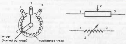
Fig. 4-3. Potentiometer shown in schematic form (left). Corresponding terminal
positions are shown on the symbols (right).
There is also a class of variable resistors intended to be adjusted to a particular resistance setting and then left undisturbed. These are known as preset potentiometers (alternatively, preset pots or just presets). They are small in size and more limited in maximum resistance value -typically from 100 ohms to 1 megohm. They are usually designed for adjustment by a screwdriver applied to the central screw, or sometimes by a knurled disc attached to the central spindle, carrying the wiper. The latter type are known as edge presets, and similar types, with a (maximum) resistance of 5 k ohms may be used as volume controls on miniature transistor radios.
Potentiometers are used specifically in a circuit where it is necessary to be able to adjust resistance. A typical example is the volume control in a radio circuit. In this case the potentiometer may be designed so that at one end of the track the wiper runs right off the track to break the circuit. Thus the volume control can also be connected up to work as an on -off switch, using this extra facility provided.
Another practical example is the replacement of fixed resistors in a voltage divider by a single potentiometer to make the circuit variable in performance. Thus, the circuit previously described in Fig. 3-7 ( Section 3) always gives a predetermined voltage at the tapping points (provided the supply voltage remains constant). Replacing resistors R1 and R2 with a potentiometer, as shown in Fig. 4-4, with the tapping point taken from one end of the potentiometer and the wiper, will give a tapped voltage which is fully variable from the full supply voltage down to zero, depending on the position of the wiper.
In practice, in a variable-voltage circuit of this type, it may be necessary to leave a fixed resistor in series with the potentiometer to limit the current being drawn in the event that the potentiometer has been adjusted to zero resistance and the tapped circuit is broken or switched off with the original supply still connected. Without the fixed resistor, the supply would then be shorted. The value of a fixed resistor would be calculated to limit the current drawn in such a case to a safe level.
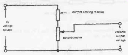
Fig. 4-4. A practical adjustable potential divider.
With a fixed resistor in series with the potentiometer, of course, the maximum voltage that can be "tapped" from the potentiometer is equal to the supply voltage less the voltage dropped by the fixed resistor.
The main thing to watch in such a circuit is that the power rating of the potentiometer is adequate to accommodate the voltage and current drain in the tapped circuit. But, it has one further advantage over a fixed resistor potential divider: When a load is added to the tapped circuit, this will add resistance in that circuit, causing a further voltage drop. Unless this is allowed for in calculating the values for the fixed resistors in a potential divider, this will mean that the load receives less than the design voltage.
With a potentiometer replacing the two fixed resistors, its position can be adjusted to bring the load voltage back to the required figure (Fig. 4-5). This considerably simplifies the design of a potential divider where the load resistance is known only approximately, or not at all.
dc voltage source I load resistance
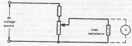
Fig. 4-5. The potentiometer can be adjusted to give required voltage across
the load.
CIRCUIT RULES FOR RESISTORS
In the case of resistances connected in series (Fig. 4-6), the total resistance in circuit will be the sum of the various resistor values, i.e., total resistance = R1 + R2 + R3 + R1 R2 R3 R4 total resistance R1 + R2 + R3 + R4 Fig. 4-6. Resistors in series.
In the case of resistors connected in parallel (Fig. 4-7), the total effective resistance is given by:
… where R is the total resistance.
In the case of two dissimilar resistors:
R =
or remembered as:
total resistance =
R1 R2 product of resistor values sum of resistor values R3
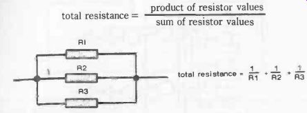
Fig. 4-7. Resistors in parallel.