AMAZON multi-meters discounts AMAZON oscilloscope discounts
As noted in Section 2, the current which flows in a simple dc circuit is dependent on the applied voltage and the resistance in the circuit. Voltage can be measured directly by a voltmeter placed across the battery (or dc source) terminals; and current by an ammeter connected in series in the circuit, as in Fig. 3-1. This diagram also shows the circuit components in symbolic form (in the case of a resistor this can be drawn as a plain rectangle or a zig-zag line).
OHM'S LAW
The relationship between voltage (E), current (I) and resistance (R) is given by Ohm's law:
In plain language:
amps -
I = -
R volts resistance in ohms or the formula can be rewritten:
volts = amps x ohms
volts ohms = amps
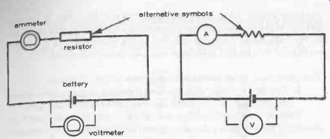
Fig. 3-1. Basic dc circuit drawn in two ways, with meters for measuring current
and voltage indicated.
This is one of the most basic and most useful laws of electronics and is equally applicable to ac circuits which are purely resistive (i.e., do not have additional "resistance" effects produced by the current being alternating rather than steady).
Ohm's law makes it possible to calculate (and thus design) the performance of a simple dc circuit. For example, suppose we need a current of 200 milliamps (mA) to flow in a particular circuit to be powered by a 6 -volt battery. Using Ohm's law, the corresponding circuit resistance required to give this current can easily be worked out:
volts 6 ohms =
amps 0.200
= 30 ohms.
Components are connected by wires, but the resistance of wiring is small enough to be negligible. Thus in a simple de circuit it is the effective total of all the resistor values and other components which offer resistance. Just what this total value is depends on how the various resistors which may be present are connected--see Section 4.
In some cases it is easy to calculate the resistance of a typical load. For example, a flashlight bulb is usually rated by volts and the current it draws.
Ohm's law can then be used to find its nominal resistance. For example, if a bulb is rated at 6 volts and 50 mA, from Ohm's law:
Resistance = 6 = 120 ohms.
0.05
There is just one snag to this method of estimating load resistance. With filament bulbs, for example, the specified current drawn refers to the bulb in "working' conditions with the filament heated up. Its actual resistance initially when the filament is cold can be considerably lower, drawing more current through the bulb. This may, or may not, be a disadvantage in a particular circuit. Also, there are other types of load, like dc electric motors, where the effective resistance varies considerably with the speed at which the motor is running. Initially, such a motor will have a very low resistance, its effective resistance then increasing with speed.
Two other basic relationships also apply in a simple dc circuit:
1. The current value will be the same through every part of the circuit, unless a part of the circuit involves parallel -connected paths.
Thus, in a circuit (A) of Fig. 3-2, all the resistors in the circuit are connected in series so that the same current will flow through each resistor.
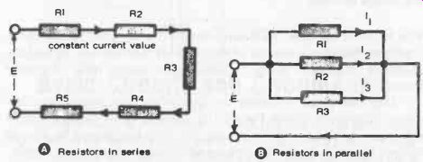
Fig. 3-2. Current has the same value through all resistors connected in series;
but is different through each resistor connected in parallel.
In circuit (B) of Fig. 3-2, the resistors are connected in parallel. In this case each resistor represents a separate path for the current and the value of current flowing through each "leg" will depend on the value of that resistor. These current values can be calculated from Ohm's law:
through resistor 1, current =
through resistor 2, current through resistor 3, current E R1 E R2 E R3 The current flowing through the wiring part of the circuit will be the sum of these three currents, i.e.,
E E E or E 1 1 1 R1 + R2 + R3 R1 + R2 + R3
2. The voltage throughout a simple dc circuit is not constant but will suffer a "drop" across each resistor. This can be illustrated by the circuit shown in Fig. 3-3, where the voltages across the individual resistors are calculated (or measured with a voltmeter) as V1, V2 and V3. The total resistance in the circuit is R1 + R2 + R3.
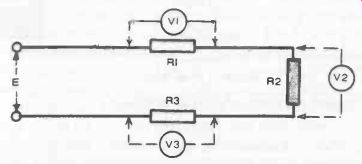
Fig. 3-3. Resistors drop voltage in a dc circuit.
The current (which will be the same throughout the circuit) is given by:
I= R1 + R2 + R3
We then have the conditions:
V1, measured across
R1 = current x resistance = 1 x R1 V2, measured across R2 = 1 x R2 V3, measured across R3 = 1 x R3
Each of these voltages will be less than E.
Comparison with a hydraulic circuit again (see Section 2) can help understand how a resistor works as a "voltage dropper." In a hydraulic circuit, pressure is analogous to voltage in an electronic circuit. The equivalent to a resistor is some device restricting fluid flow-say a partially closed valve. Flow through this resistor will produce a pressure drop.
Similarly, the flow of electricity through a resistor will produce a voltage drop.
VOLTAGE-DROPPER CIRCUIT
The above is now reworked as a practical example. To power a 6 -volt electrical appliance (say a 6 -volt transistor radio) from a 12-volt battery. In this case, the appliance is considered as a resistance load. To "drop" the voltage from 12 to 6 across this load, a dropper resistor, R, is required in the circuit shown in Fig. 3-4. It remains to calculate a suitable value for this "dropping" resistor, but to do this it is necessary to know the effective resistance of the load. (If this is not known it can be measured with an ohmmeter.) Suppose it is 100 ohms.
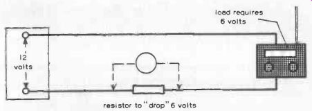
Fig. 3-4. Practical application of a dropping resistor.
Using Ohm's law again, if this load is to have 6 volts applied across it, and its resistance is 100 ohms, the current required to flow through the circuit is:
1 = L 100 = 0.06 amps (60 milliamps)
This same current will flow through the rest of the circuit. This, considering the circuit from the 12 volt end:
total resistance required - 0.06 = 200 ohms.
The load already contributed 100 ohms, so the value of dropping resistor required must be 200 - 100 = 100 ohms. A further calculation will show the voltage drop across this resistor will be:
V = 0.06 x 100 = 6 volts.
This particular example also demonstrates another simple rule concerning dropping resistors. If the voltage is to be halved, then the value of the dropping resistor required is the same as that of the load.
POWER IN THE CIRCUIT
The power developed in a circuit by virtue of the electrical pressure (volts) and resulting current flow (amps) is given by the product of these two values, and measured in watts. Thus: power = watts = volts x amps This same definition applies both to dc and ac circuits.
Power is used up in producing a useful result in making the circuit "work" (whether this be operating a radio, driving an electric motor, heating an electric element, etc.). But all components which have resistance absorb a certain amount of power which is "waste" power normally dissipated in the form of heat. No practical device can work without some resistance in the circuit, and thus some power loss is inevitable. More important, the heating effect must not be so great that the component is damaged. Thus components normally have a power rating which should not be exceeded. In specific cases, even when operating within their power rating, provision may have to be made to conduct heat away from the component-as in the case of "heatsinks" used with power transistors.
Referring to the example of the dropping resistor, this definitely wastes power to the tune of 6 (volts) x 0.06 (amps) = 0.36 watts. To be on the safe side, therefore, the resistor chosen would need to have a power rating of at least 1/2 watt, and would also have to be placed in a position where it receives adequate ventilation to prevent heat build-up in the surrounding air.
The majority of transistor circuits work on low voltages, with low current values, and so components with quite moderate power ratings are usually adequate. Circuits carrying higher voltages and currents demand the use of components with correspondingly higher power ratings, and often need even more attention to ventilation. Thus, the actual value of a component is only part of its specification. Its power rating can be equally important.
Note that since V = IR, power can also be calculated as:
watts = (current)^2 x Resistance = I^2 R
This is often a more convenient formula for calculating power in a particular part of a circuit.
SHUNT CIRCUITS
A shunt circuit is used to "drop" a current flowing through a particular component. It normally comprises two resistances in parallel, one resistance being the component resistance and the other the shunt resistance.
The appropriate value of the shunt resistance is again calculated directly from Ohm's law.
A typical example of the use of a shunt resistance is to adapt an ammeter movement to measure different current ranges (as in a multimeter). In this case the "load" resistance is that of the coil of the ammeter, which is initially designed to give a full-scale deflection with a particular current flowing through it (call this I1). The instrument cannot measure any higher current than I1 since this would simply tend to carry the pointer past its full deflection, and very likely cause damage. Thus, the meter is designed to handle the lowest current range required, and a shunt resistor (or a series of shunt resistors) added which can be switched into the meter circuit to extend the range. Figure 3-5 shows this arrangement with just one shunt resistor connected for switching into the circuit.
If the shunt resistor is to extend the ammeter range to a higher current, I2, giving full-scale deflection, then the required value of the shunt resistor follows from:
1. Current which has to flow through shunt is I2-I1. This means that a current greater than I1 will never flow through the meter movement (unless the actual current applied to the meter exceeds I2).
2. Voltage drops across the meter = I1 x Rm (where R. is the resistance of the meter).
3. Shunt resistance required is therefore: voltage drop across instrument current flow through shunt.
Again, there is a simple rule to follow if the current range of the meter is to be doubled. In this case the shunt resistance required is the same as that of the meter.
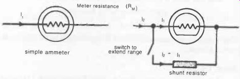
Fig. 3-5. Extending the range of a milliammeter.
AMMETER INTO VOLTMETER
An ammeter, which is an instrument used for measuring current, can also be made to measure volts by connecting a resistor in series with the meter--Fig. 3-6. This, in fact, is another example of a voltage dropper.
Again, if the maximum meter current for full-scale deflection is II, the total resistance which must be in circuit is: total R = v i where V is the voltage range it is desired to measure.
The value of the series resistor required is this total resistance less the resistance of the meter (the latter may be negligible in comparison with the value of series resistor required and its likely tolerance-see Section 4).
Again, several series resistors may be used, switched into the circuit individually to provide different voltage -measuring ranges on the meter movement, as shown in the right hand diagram of Fig. 3-6.
ammeter movement; resistor; simple voltmeter; volt-meter with five ranges
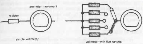
Fig. 3-6. Converting an ammeter into a voltmeter.
DIVIDERS
A voltage divider is yet another example of the practical application of a "voltage dropper." The basic circuit is shown in Fig. 3-7, and since the current flow through R1 and R2 is the same, the following voltage values apply:
V1 = source voltage (e.g., battery voltage) V2 = V1 x R1
V3 - V1 x R2 R1 + R2 (Note: R1 +1 R2 is the current flowing through R1 and R2).
voltage source
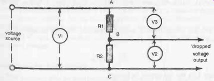
Fig. 3-7. Basic potential divider circuit.
It follows that by suitable selection of values for R1 and R2, virtually any lower voltage than V1 can be tapped from points A and B, or B and C (or both). It also has the advantage that it is not necessary to know the load resistance before suitable "dropper" resistances can be calculated. It could thus be a more practical alternative for the example described in Fig. 3-4, but connection to a load will, of course, result in a further drop in voltage.
If the resistance of the load is known, then there is no particular problem with a fixed resistor voltage divider. Calculate the value of R2 (Fig. 3-7) on the basis of no load resistance, then subtract the actual value of the load resistance from this to arrive at the required value for R2. (In the complete tapped circuit, R2 and the load resistance will effectively be in series.)
BASIC AC CIRCUITS
As explained in Section 2, the voltage and current flow both alternate in ac circuits, with the possibility of one leading or lagging the other. Also, it was intimated that the effective resistance offered by resistance components may be modified (usually increased) by reactive effects. These effects become increasingly marked as the frequency of the ac increases, and at radio frequencies are more pronounced than pure resistance.
It is possible to obtain an ac circuit which is purely resistive, particularly at lower frequencies, in which case Ohm's law is equally valid for such circuits as it is for dc circuits. Ohm's law can also be applied to ac circuits in which reactive effects are present, but in slightly modified form. These reactive effects are described specifically as reactance and impedance.
Reactance is the circuit loading effect produced by capacitors and inductances (coils). It is measured in ohms and designated by the symbol X.
Its actual value is dependent both on the component value and the frequency of the ac.
In the case of capacitors, capacitive reactance (usually designated Xc) is given by:
(Xc)c = 1 / 2 pi fC
... where f is the ac frequency in Hz, C is the capacitance in farads, and pi = 3.1412.
In the case of inductances, inductive reactance (usually designated XL) is given by:
XL = 2 pi fL
where L is the inductance in henrys If the ac circuit contains only reactance (i.e., does not have any separate resistance), then X takes the place of resistance (R) in the Ohm's law formula:
I= X
In practice, reactance present is also usually associated with resistance, the resulting combination representing the impedance (Z) of the circuit.
If reactance and resistance are in series:
z= R2 _E_)(2
If reactance and resistance are in parallel:
Z= /R2 +X2 RX
Again, impedance (Z) takes the place of resistance in the Ohm's law formula:
These are the basic formulas for ac circuit calculations.
POWER FACTOR
Power factor is something specific to ac circuits, although it is only the resistance in such circuits that actually consume power. This power consumed can be calculated as the product of the square of the current flowing through the resistance and the value of the resistance, i.e., I^2R watts. The apparent power in the circuit is the product of ac voltage and current, correctly specified as volt-amps.
The ratio of the power consumed to the apparent power is called the Power factor, usually expressed as a percentage. If the circuit is purely resistive, then the power factor will be 100 percent (since all the apparent Power is consumed in the resistance). Reactance does not consume power, so in a purely reactive circuit the power factor is zero. When a circuit contains both resistance and impedance (i.e., reactance), then the power factor will always be less than 100 percent, its value depending on the resistance present.
Dc and Ac in the Same Circuit
It is quite possible to have both dc and ac flowing in the same circuit. In fact, this is the principle on which most radio and similar circuits work. The dc is the basic source of electrical supply, on which various ac currents are superimposed. The one essential difference is that dc can only flow through a continuous circuit, whereas ac can pass through components such as capacitors which present a "break" in the circuit to dc. These effects can be used to advantage to "isolate" stages in a circuit.
In the type of circuit shown in Fig. 3-8, for example, an input comprising a mixture of dc and ac is applied to the left-hand side of the circuit. If only the ac component of the signal is required, the dc content can be blocked by a capacitor (C1). Meantime, the next part of the circuit which has to deal with that signal is powered by dc from the source supply (say a battery), probably via resistors R1 and R2 acting as dividers to get the voltages correct for that stage (other stages may need different working dc voltages, all coming from the same source). The output signal from this stage then consists of a mixture of dc and ac. If only the ac content is wanted for passing to the next stage, a capacitor (C2) is again used as a block for dc.
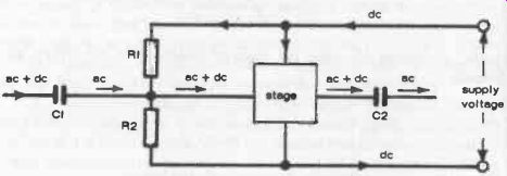
Fig. 3-8. Diagrammatic representation of flow of ac and dc in a circuit.