A HI-FI RECORD PLAYING SYSTEM is called a record deck. It constitutes a program signal source for connecting to a hi-fi amplifier and thus consists of a turntable unit mounted in a plinth - usually with a hinged transparent plastics dust cover at the top - a pickup arm and a pickup cartridge. Each item has its own specification; but there is merit in looking at the specifications of all the items together because the resulting quality of reproduction can be influenced by their compatibility- or lack of compatibility! It is particularly important that manufacturers provide full specifications of a record deck when it does not include a cartridge. This then makes it possible for users to choose a cartridge of suitable compatibility for the arm.
Example Specs
In the example specifications which follow, the three items - turntable unit, pickup arm and cartridge - are presented separately. The subsequent text discusses , where appropriate, the aspects of compatibility and reveals the effects that the mounting plinth and dust cover can have on the reproduction.
You will also find more information in this in Section 8.
Turntable Parameters
Features: direct drive motor, servo-control, auto-stop and lift and fine speed control (i.e. pitch control)
Speeds: 33.3 and 45 r. p.m.
Turntable mass: 1 kg
Turntable damping: compliant mat
Time to reach correct speed: 1.5 sec. at 33.3 r.p.m.
Speed accuracy at 33.3 r.p.m.: within 0.1%
Long-term speed drift: less than 0.1%
Speed change under steady-state load: -0.2%
Wow and flutter: less than 0.1%
DIN peak weighted
Rumble: -65dB DIN B weighted
Arm--Parameters
Features: detachable - universal fitting - head-shell, side-thrust correction adjustment and overhang adjustment
Arm mass including headshell: 18g
Headshell mass: 7.5g
Lateral friction: 50mg
Vertical friction: 20mg
Side-thrust correction range: zero to 250mg at rim
Cartridge mass accommodation: 2 to 16g
Playing weight range: zero to 3g
Playing weight calibration error: less than 3%
Manual lifting/lowering drift/speed: none/1sec.
Type: moving magnet
Mass: 6g
Cartridge Parameters
Stylus: naked elliptical (0.0003 x 0.0007in.)
Fixing: 1-in. centers
Compliance: 15x 10-'cm/dyne
Effective tip mass: 0. 6mg
Frequency response: 10Hz to 25kHz -2dB
Channel separation: 30dB 1kHz and 20dB 10kHz
Tracking weight range: 1.5 to 3g
Channel balance: within 2dB over response
IM D at -&dB: less than 1%
Impedance: 860 ohms/280 mH
Best tracking weight: 2.5g Output at 5cm/sec. recording level: 5mV Tracking threshold: pulsed high-frequency 24cm/sec. at 2g; middle and low frequencies 35cm I sec at 2g (all peak levels) A typical specification may include other items such as dimensions , weight, clearance for dust cover, etc. On the other hand, some manufacturers' specifications may be far less detailed than our examples. Our lab measures most of the parameters exampled, for even though all of these may not directly contribute to the listening experience, they can be important in one way or another, particularly to ensure compatibility.
We shall now interpret them in turn, starting with the parameters of the turntable unit, in the order presented in the examples.
TURNTABLE PARAMETERS
Features
These merely tell you of the nature of the motor, whether direct -drive or belt drive, whether there is servo-control for speed, pitch control (which is a fine speed adjustment) and so forth.
There are some enthusiasts who prefer belt-drive motive force in spite of the advances recently made with direct-drive motors . Section 8 has more information about this. Speed accuracy is often dictated by the supply mains frequency, but more expensive motors use a quartz oscillator for even greater accuracy.
Speeds
The trend is nowadays for motors to be equipped only with two speeds--33.3 and 45 r.p.m. If you are interested in playing early 78s, therefore, you will have to ensure that the motor provides that speed (some still do) and that you have a suitable stylus in the pickup.
Turntable Mass
This is important when the drive is via a belt from a relatively small motor.
Some servo-controlled direct-drive (and belt drive) units use relatively low-mass turntables to secure swift reaction to load change. However, it is now being regarded as important to use relatively massive turntables even for direct-drive systems in order to iron-out minute, transient-type speed fluctuations, which are claimed in some cases to affect the reproduction, impairing the ambience and music definition.
Turntable Damping
A turntable in its 'raw' state has the unfortunate characteristic of being high-frequency resonant. That is, when tapped it will emit a bell-like ring. If a pickup stylus is placed on a stationary, undamped turntable and the output of the pick-up is connected to an amplifier feeding an oscilloscope, when the turntable is tapped a decreasing amplitude sinewave (oscillation) will appear on the screen. If a loudspeaker is connected to the amplifier, the 'ring' will be heard quite dramatically through this . When playing a record, therefore, minor turntable resonances might well be excited by the sound field from the loudspeakers impinging upon the turntable, particularly at high levels of reproduction. Clearly, this is bound to have a degrading effect on the reproduction.
A degree of damping is provided by the turntable mat . Some designs include further damping below the turntable, in the casting shell. Such resonances of the turntable and of other items of the record deck are responsible for the 'different soundings ' of different record decks, including the nature and design of the plinth, the dust cover, pickup arm and ancillary devices, such as the side-thrust correction arrangement and the lifting/lowering device.
Acoustical Feedback
Although not a parameter , this condition can be encouraged by resonances and inadequate attention to their damping. When a pickup is resting on a record and the deck is connected normally to the amplifier, a somewhat inefficient microphone situation develops . When the deck is tapped this will be heard through the loudspeakers.
Thus, when the record is playing, the sound picked up by this 'microphone' will be conveyed back to the loudspeakers through the amplifier. Owing to the resonances and the distortion on this feedback signal there can be a marked impairment in the reproduction, particularly at high sound intensities.
This effect is well known and has been with us since the advent of the record deck; but it seems to have been forgotten and is recently being rediscovered. When the sound intensity is sufficiently strong and the feedback loop gain exceeds unity, the resonances can produce a positive feedback condition. When this happens a dramatic 'howl' builds up (called howl round) at a frequency dictated by the various system and room resonances (including those of the pickup system and loudspeaker) . To eliminate the howl it is necessary to reduce the volume setting, switch in a low filter or retard the amplifier's bass control. A limit is thus set to the bass output and sound intensity that can be raised in a given room under these conditions from a gramophone record. If you operate at a volume setting close to the howl round threshold the reproduction is bound to be noticeably colored.
This condition and the resulting sound coloration have been considered in our earlier hi-fi guides (for example, page 186 of Pickups and Loudspeakers, page 153 of ABC of Hi-Fi, page 131 of Improving Your Hi-Fi and page 155 of Audio Technician , s Bench Manual, which also proposes a method of measurement) . As mentioned in some of these references , a quick test is to place the pickup on a stationary record with the amplifier system operative, then to turn up the amplifier 's volume control to find the howl round threshold setting. Turn back just below the threshold immediately, and then tap the deck plinth to discover its degree of microphony.
In general, a deck which allows a high volume control setting and one which is only mildly microphonic will audition better than one which goes into howl round at a relatively low volume control setting and which is exceptionally microphonic.
Electrical coupling from the power amplifier section back to the low-level pickup preamplifier via leads or a common impedance can also impair the listening experience. Amplifiers using separate preamp and power sections are less prone to these problems, which is one reason why they sometimes audition more favorably than integrated amplifiers.
Time to Reach Correct Speed
Unless you are a disc jockey, this is not a particularly important parameter. It is a measure of the time it takes the turntable to arrive at its stabilized speed after switch on. High torque motors can take the turntable to an accurate 33.3 r.p.m. in less than 1 second. On the other hand, you don't want to wait too long for the turntable to arrive at full speed! Direct-drive motors generally arrive at the correct speed earlier than belt-drive counterparts.
Speed Accuracy
If you are blessed with perfect pitch it is essential for the turntable to spin precisely at the recorded speed. Measurement is commonly made (in our lab, anyway) with a very accurately recorded frequency tone disc, the frequency then being read during replay on a digital frequency counter . An error of 0.1 % or less is acceptable.
Many turntables are equipped with a strobe indication of speed which use the mains frequency as a reference. Others use the greater accuracy of a Quartz crystal oscillator as the reference. Not all records are recorded at absolutely the correct speed and for people with perfect pitch a fine speed control (pitch control), having a range of round ±5%, would be desirable.
Long-Term Speed Drift
As you don't want to have the bother of correcting the speed at frequent intervals , once correctly set the speed should hold steady for protracted periods . Very slight speed drift is not easily detected on the strobe, but it can be a source of annoyance for people with perfect pitch.
Electronic-controlled motors appear to be more susceptible to the aberration than the basic belt-drive versions , particularly when they are equipped with a fine control for each speed. Slight drift with temperature change of components in the control section has been known to precipitate a change of up to 2% during a record playing session.
Speed Change under Load
When a normal load is placed on the rotating record there should be no significant change in speed. Some units with relatively low torque motors unfortunately exhibit a speed change when a 'dust-bug' or similar brush-type dust remover is used. This is particularly noticeable when the turntable mass is relatively low.
When electronic speed control is employed, however, the extra load results in the turn-on of more urge and, conversely, when the load is removed the urge is reduced. Sadly, this is not the whole story because when a record is …
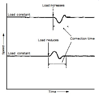
Fig. 5. 1: Showing the effects of under- and over-shoot of a servo-controlled
turntable unit with load changes (see text for more details) .
… being played the load is continuously varying owing to the changing drag resulting from the changing levels of groove modulation.
Electronic control works on the servo-controlled closed-loop principle which, by its very nature, can tend to exhibit mild under- and over-shoot effects depending on the design and the loop damping. For example, when the load suddenly increases the system might slow momentarily before the extra urge becomes effective; then when the extra power is fed to the motor it may be a little more than required, thereby giving a small overshoot before the system stabilizes.
Conversely, when the load is suddenly reduced there might be a speed increase overshoot before total stabilization. These effects are shown in elementary form in Fig. 5 .1.
Thus, with continuously changing load, such as presented by a wide dynamic range record, there might be a whole complex series of under- and over-shoots which might introduce a form of very low-level, though undesirable 'modulation' on the replay signal. This could be in the form of a 'flutter' effect following steep transient recording-level changes.
It is considered by some people that this is a significant reason for one turntable unit 'sounding' different from another. It is a perfect valid observation, of course, but one which is extremely difficult to prove objectively (by measurements). It is possible to analyze flutter sidebands using a spectrum analyzer with a very narrow swept filter - circa 1Hz, and this method, in conjunction with recorded transients, is currently being used by our lab to seek a more objectively valid way of expression.
So far, it appears that the mass of the turntable has a significant influence on the effect, the larger masses virtually ironing-out completely the tendency of such 'flutter' when the recording level changes occur quickly. Nevertheless, there is still much more we have to learn to secure a meaningful objective/subjective correlation. Right now, however, it seems that the greater the mass of the turntable, the better! Wow and Flutter Since this is measured on steady-state signal , such as a constant 3kHz recorded sinewave, it fails to expose the effects previously referred to. The vast majority of turntable units have highly acceptable wow and flutter figures of 0.1 % or less (DIN peak weighted) , and wow and flutter on steady state signal is not subjectively detectable when below about 0.2%.
Rumble
Rumble consists of very low-frequency components of the turntable unit's bearings coupled back to the amplifier system in terms of electrical signal by the pickup. As with S/N ratios, a weighting filter is often used to emphasize the most annoying components while attenuating those which are regarded as less subjectively troublesome. A common weighting is DIN B, and provided the ratio referred to a given level of record modulation (often 10 cm/S) is round the -60 to -65dB mark rumble should not cause you distress.
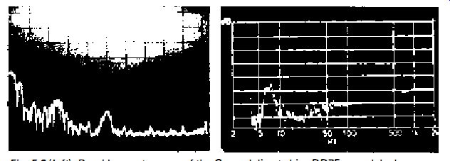
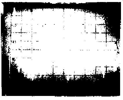
Fig. 5.2 (left) : Rumble spectrogram of the Garrard direct-drive 0075
record deck.
Fig. 5.3 (right: A logarithmic sweep over 4 to 100Hz, showing the arm/ compliance resonance round 7Hz.
A simple rumble parameter, however, fails to tell the whole story. More detailed reviews carry a rumble spectrogram which clearly shows the level and frequency of the rumble components below the reference signal level . Such a spectrogram is given in Fig. 5.2. The vertical scale is 10-dB per division (the top 0-dB horizontal line corresponding to 10 cm/S recording level) and the horizontal scale 10Hz per division.
Discounting the 'starting signal ', this shows a fairly heavy component round 5Hz at -55dB and a group of components at about -68dB round 25Hz. The signal at the middle of the sweep, at 50Hz, shows the amount of mains hum picked up by the deck which, at -74dB, is acceptable. This was taken from the excellent Garrard DD75 record deck, which uses a direct-drive motor.
Some direct-drive motors, particularly the earlier versions , were prone to harmonic production of the drive frequency, and in some cases components at about 100, 150, 20Hz etc. were detected at different levels. These were caused by magnetostriction effects of the rotor producing vertical vibrations of the turntable shaft.
In some cases they tended to excite turntable resonances, and for this reason some of the early direct-drive units were subjected to adverse criticism.
These problems have now been largely resolved, and it needs some imagination to say conclusively that a belt-drive unit auditions better than a direct drive unit, or vice versa!
ARM PARAMETERS
Features
Again, these tell you of the nature of the arm, the type of headshell used and whether it is detachable, and about the various adjustments . These may interest you more if you are purchasing an arm independently of the turntable unit and, perhaps, cartridge.
Arm Mass
This is an important parameter because it has a bearing of compatibility with regard to the pickup cartridge compliance. We interpret compliance later, but at this stage if you can imagine a weight (mass) supported by a spring (compliance) it is fairly easy to visualize that if the mass is moved or vibrated in some way it will wobble on the compliance. This periodic motion constitutes a resonance mode, the rate of wobble being the resonance frequency.
Although the pickup arm is counterbalanced and then deliberately unbalanced to provide the tracking force for the cartridge, the value of mass remains . The stylus assembly of the cartridge is of a 'springy' nature, of course, which is where the compliance comes in. Thus a resonance frequency occurs as the result of this compliance and the arm mass.
How long the wobble (mainly up and down in this case) goes on for depends on the mechanical damping, in rather the same way as the 'soft' pedal of a piano damps the vibrations (shortens the vibration time) of the strings. With a pickup system the damping may be wholly built into the cartridge or into both the cartridge and the arm. It is undesirable for the vibrations to be protracted; but if there is too much damping in the cartridge certain aspects of the tracking can suffer. Compliance versus damping is one of the many compromises of pickup system design.
Resonance Frequency
Vibrations, of course, are imparted to the stylus by the groove modulation, and when these vibrations correspond to the resonance frequency the electrical output at that frequency increases. At frequencies below resonance the output falls fairly swiftly. This means that if the resonance frequency occurs at, say, 40Hz, the low bass output of the pickup is inhibited.
There are extremely few - if any - pickup systems which exhibit a resonance due to the factors discussed at such a relatively high frequency. In general, the resonance range is between about 4 and 15Hz, only a few low-mass arm systems reaching the upper frequency, which is the most desirable end of the range.
With a cartridge of given compliance, the lower the effective mass of the arm (including headshell and cartridge) , the higher the resonance frequency.
We shall see later that the resonance frequency falls with increase in cartridge compliance (reduced stiffness), and because top-flight 'trackability' calls for a cartridge of fairly high compliance, the best arms are those of the lowest effective mass when properly designed. It should be remembered that it is always the stylus end of the cartridge and the record groove which has to move the arm mass, so from this aspect alone, the lower the mass the better.
Damping
When the low-frequency resonance is being excited by a corresponding frequency modulation (or, perhaps, record warps !), the cartridge end of the arm is vibrating up and down more violently than it would without the resonance. This can affect the upper-frequency tracking because on the upward travel the downward tracking force is partially cancelled. Damping reduces the amplitude of the resonance, thereby improving the tracking, while also helping to reduce cartridge coloration.
The sweep oscillogram in Fig. 5.3 shows an arm/compliance resonance round 7Hz on a logarithmic sweep starting at 4Hz and continuing to 100Hz.
The vertical scale is 5dB per division, so the resonance has a peak of some 7.5dB above the output at 100Hz. Without damping the peak would be even higher, and then there would be the probability of groove jumping if warps or record modulation (which is extremely unlikely at such a low frequency) excited the resonance.
There are various methods used for damping arms . A common one utilizes a 'rubberized' arm section coupling near the counterbalance weight. Sometimes the damping is applied by a viscous fluid.
The latest Shure V15/IV cartridge is equipped with a viscous-mounted, carbon-fiber damping brush, which serves as a groove cleaner and static discharger.
Headshell Mass
The total effective mass of the arm includes the mass of the headshell and cartridge, so for a low mass system both of these items should be as light as possible. The mass of a typical detachable headshell is round 7.5g, though a headshell which is fixed or integral to the arm may have a lower mass.
Lateral Friction
Because of the currently used very low tracking forces, it is essential for the friction of the arm bearings to be as small as possible. If there is too much lateral friction the tracking will suffer badly and groove jumping may be a symptom.
The measurement is often made by applying a measured force at the stylus tip and increasing this until the arm just starts to move. This is called the 'break friction threshold force' . A top-grade arm will return a force as low as an equivalent 20mg. Provided the value is not much higher than 50mg you should be able to track high compliance cartridges without trouble (always assuming the mass of the arm is not too high) . Vertical Friction This is measured in the same way but with the arm counterbalanced and with the force being applied at the top of the cartridge or headshell . A good value is, again, an equivalent 20mg.
Side-Thrust Correction Range
Pivoted arms are styled geometrically to minimize lateral tracking error by a combination of head overhang and offset . The offset angle is provided either by a straight arm and suitably angled headshell or by a curved arm. Overhang is obtained by arranging for the path of the stylus to occur a little in front of the record spindle.
The requirement is to compensate for the tracing distortion which would otherwise result from the arced path of the stylus taken ·by a pivoted arm relative to the pure radial cut of the recording. The technical factors involved are fully discussed on pages 64 to 67 of the Pickups and Loudspeakers guide.
A few decks are equipped with what is usually called a 'radial tracking' pickup. With these the arm is short and straight and is arranged to track a straight line across the radius of the record. Since this path follows that of the cutter that formed the groove of the record in the first place, tracking error does not occur and so the geometric correction just mentioned is not required.
However, most arms are pivoted, and because of the geometry the pickup has a natural inclination to pull inwards while playing. This is called sidethrust. This tends to deflect the stylus to one side of the groove more than the other side. For a given tracking performance, this imbalance calls for a slightly greater downward force. It can also affect the balance of stereo separation between the two channels.
A hi-fi arm is fitted with a device that introduces a slight outward pull to neutralize the sidethrust . This is called sidethrust correction. There are three main methods of achieving this -magnetic bias, spring bias and gravity bias , the latter often using a small weight dangling on a thread.
Correction Force
The amount of correction force required depends on several factors , including the co-efficient of stylus/groove interface friction, depth of recording (i .e. recording level) and the geometry of the stylus tip. The adjustment must be made under working conditions, and even at best it can only be a compromise owing to the changing level of modulation and hence the changing drag on the stylus. Test records are available with a range of modulation levels to secure the best compromise.
The arm includes some means of adjusting the bias , which should be less at the outer diameter of a record than the inner diameter, and a typical range at the outer diameter is from zero to a maximum of about 250mg. The adjustment is eased if it can be performed while a record is actually playing. Reasonably correctly adjusted, side-thrust correction can reduce the tracking force by about 20 % and improve the left-on-right and right-on-left separation balance.
Cartridge Mass Accommodation
Latter-day cartridges may range in mass from about 5-10g. When a cartridge is fitted to an arm the counterbalance weight is adjusted for accurate arm balance prior to turning on the tracking force. It is thus necessary to ensure that the arm will counterbalance accurately when the cartridge of your choice is fitted. There are not many arms that would fail to counterbalance today's cartridges.
Playing Weight Range
The arm, of course, should be capable of adjusting playing weight (more correctly, playing force) over the specified range of the cartridge to be used.
However, while relatively small forces can be applied by the majority of arms, not all arms are capable of providing the forces required by relatively high tracking force cartridges . If you use several cartridges of different tracking ranges , therefore, make sure that the arm will accommodate them all.
Playing Weight Calibration Error
The tracking force is turned on by some form of calibrated adjustment. The accuracy of the calibration is important and avoids the use of an external balance for setting the force. Most arms which earn the hi-fi label exhibit quite good accuracy in this respect . Some arms , however , have no calibration, so with these it is essential to use an external playing weight balance for the adjustment.
Lifting/Lowering Device
Many of these are damped in some way so that the downward action is slow and precise. It is also essential for accurate cueing that there is no arm drift during the lowering action. This parameter defines the rate of descent and the stability of lowering.
Maximum Lateral Tracking
Error Although this parameter is not always given, you will sometimes come up against it in arm specs . It indicates the maximum amount of lateral tracking error when the arm/ cartridge combination is correctly adjusted in relation to the overhang and offset geometry over the full path of the stylus. A good arm should not introduce an error much greater than 1 · 5 degrees.
Although the offset angle is fixed by the design of the arm, there is provision to adjust the overhang either at the arm bass or at the headshell (slots to slide the cartridge) . Adjustment optimization usually requires the use of an alignment protractor (see page 70 of Pickups and Loudspeakers) .
CARTRIDGE PARAMETERS
Type
There are two main types of cartridge - magnetic and piezo-electric, the latter including the so-called ceramic cartridge. Piezo-electric cartridges have the dual merits of low cost and relatively high output; but most enthusiasts would agree that a hi-fi cartridge should be a magnetic species. Other principles have been used but these have not found much favor.
There are variations of the magnetic principle, which include the moving coil where the magnet is fixed and the coils vibrate in sympathy with the stylus, the moving-magnet where a low mass cantilever carries the stylus tip one end and a very small magnet the other end, the signals extracted from coils , the induced-magnet where a strong magnetic field is places in proximity to a low mass armature coupled to the tip working in conjunction with coils, variable reluctance which is similar to the moving armature type where the vibrating armature effectively varies the magnetic field round the signal coils, and so forth.
All the magnetic versions are capable of good performance, but the nth degree of performance strongly relates to the selection of the most desirable compromises and to the micro-precision of design and construction. This is why you can purchase a magnetic cartridge for less than (1 pound is approx $1.30 USD) £ 5 , while another of similar principle might cost up to (1 pound is approx $1.30 USD) £ 80 ($120). Mass This is merely the weight of the cartridge. Today' s magnetic cartridges range in mass over about -5 to 10g. Some of the moving-coil species have the higher mass value, which is reasonable because the compliance of this type is generally relatively low. The high compliance, super-tracking type, on the other hand, demand a small mass to avoid the resonance frequency (with the arm mass) from falling at too low a value.
Generally, however, the trend is towards smaller and smaller mass cartridges which is the most desirable direction of design, allied with low effective mass arms . The scheme is always to keep the moment of inertia as small as possible to minimize the 'load' carried across the disc by the stylus.
Stylus
Because the wavelengths of the sound modulation imparted in the groove are extremely small at high frequencies, and become smaller at the inner diameters of the groove spiral because the groove/stylus interface speed then falls, the active tip of the stylus must be sufficiently small to trace and define the small wavelengths with the least distortion.
Until the advent of the elliptical stylus, the tip radius was round 12.5 um (0.005 in.) . Some are now being made at 17.5 um (0.007 in.). This is the so called 'spherical' stylus . Of more recent years the elliptical stylus has virtually become a 'standard' in the better class and hence more expensive cartridges.
The elliptical cross-section is styled and fitted so that the wide dimension sits across the V-shaped groove without scraping along the bottom, while the smaller dimension provides optimum definition of the very short wave lengths. Common dimensions are 17.5 um (0.007in.) for the major axis and 7.5 um (0.003 in.) for the minor axis.
With the coming of quadraphony we are now seeing variants, such as the Shibata stylus (Japanese), the Ichikawa stylus (also Japanese) , the Pramanik stylus (B & O of Denmark) and the 'triradial ' stylus (Philips). These are contoured to secure the best results from 'carrier' type quadraphonic records.
The best high-frequency tracking performance demands the smallest effective mass at the stylus tip (also see under Effective Tip Mass) , and this can be influenced by the nature of the tip fixing to the cantilever. Some diamond tips require the intervention of metal for their fixing which, of course, adds to the mass. The more expensive cartridges are now adopting the so-called 'naked diamond' which fits directly into the cantilever without any intervening metal support.
Fixing
The vast majority of cartridges are designed to partner a standard headshell which has hole or slot fixing on-in. between centers .
Compliance
Compliance is a measure of the freedom of movement of the stylus . The less the stiffness, the higher the compliance. The original expression (still found in specs) is 10^-6cm/dyne. This merely means that a compliance of 1 (1 cu) is equal to a deflection of one-millionth of a centimeter when the applied force is 1 dyne.
With the more recent SI units the expression has been changed to 10^-3m/N, where N is the force in newtons . When the SI units are employed mass is expressed in kg instead of in g. It all works out to the same thing, which you can discover with a little arithmetic on your pocket calculator ! A low tracking force cartridge exhibits a high compliance (good freedom of movement of the stylus) ; but if you use a high compliance cartridge in an arm of exceptionally high mass the low-frequency resonance will fall at an undesirably low value and the high moment of inertia of the arm will result in large deflections of the stylus when negotiating record warps . It is imperative to choose a compliance to suit the arm mass.
Effective Tip Mass
When a stylus tip is vibrating under the influence of high-frequency, high level groove modulation, high accelerations and large groove-wall forces are produced. If the effective tip mass is large, therefore, the resulting forces will impair the high-frequency tracking and damage the fine modulation patterns in the groove. The effective tip mass is not only a function of the mass of the diamond itself, but also of the mass of the cantilever and the armature, moving-magnet or moving-coil . The micro-miniaturization of the parts attached to the cantilever and the use of light metal tubes for the cantilever are now bringing the effective tip mass down to 0.42mg (e.g., the AKG PSE and PSES cartridges) . There is still a lot of design activity going on in this area.
The recent Signet range of cartridges (by Audio Technica) , for example, are now available with cantilevers of titanium, beryllium and even carbon fiber-- all equipped with naked diamonds . These materials cut the mass while improving the anti-resonance properties, leading to even better translation of groove 'wriggles' to high quality sound.
Frequency Response
After correct RIAA equalization, the frequency/amplitude response of a pickup playing a swept-tone record recorded to the RIAA standard should be flat within a dB or so from 20Hz to 20kHz. Severe undulations in response generally signify unwanted resonances. We have already looked at the very low-frequency resonance resulting from the effective mass of the arm and the compliance of the cartridge.
Another resonance occurs at the high-frequency end of the spectrum as the results of the effective tip mass and the compliance of the record material and, perhaps, the compliance of the cantilever itself. To keep this resonance well above the audio pass band the effective mass of the tip must be very small--not greater than 1 mg, which is on the high side of the scale nowadays.
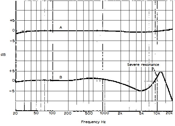
Fig. 5.4: Cartridge frequency responses. Curve A an excellent cartridge;
curve B a poor cartridge with severe high-frequency resonance.
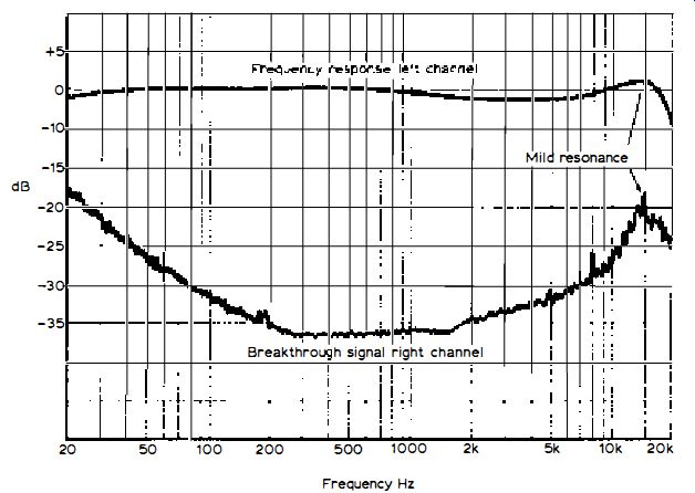
Fig. 5.5: Upper curve frequency response of left channel and lower curve
the breakthrough signal in the right channel, which is an expression of
stereo separation. When there is a resonance there is also usually a corresponding-frequency
fall in separation.
The curves in Fig. 5.4 show at A the frequency response of a well designed cartridge where the resonances are well tamed, and at B a response signifying a cartridge of relatively high effective tip mass and poorly damped resonances . There is little doubt that the cartridge responsible for A would audition much better than that responsible for B; but it is highly likely that the first cartridge would cost a number of times more than the second!
Channel Separation
If a stereo record is recorded only in one channel, the amount of signal produced in the other channel should be very much less . This is a measure of the stereo or channel separation. A top-flight cartridge will return a separation of at least 30dB at 1kHz, with lesser separation at 100Hz and 10Khz.
A good separation is required for the best stereo effect, and stability of stereo image requires the separation to be maintained to fairly high frequencies without severe changes. Equally as important, however, is the distortion on the signal in the non-speaking channel . As with FM tuners, this can be astonishingly large, so if the separation is poor the reproduction will be marred by a higher than necessary overall distortion.
The curves in Fig. 5.5 show the frequency response at the top and the stereo separation below. These curves typify a good quality cartridge. Incidentally, the separation curve is also useful for showing up resonances not so easily detected on the frequency response curve, for when there is a resonance there is usually a corresponding fall in separation.
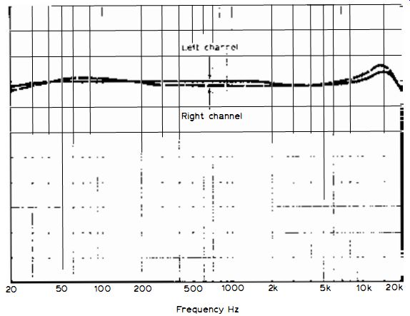
Fig. 5.6 -- Left and right frequency response curves, showing channel
imbalance over the frequency spectrum.
Tracking Weight Range
This is the range given by the manufacture for tracking force. In most cases the best tracking occurs at the highest force; but, unless it has been proved by independent tests otherwise, the maximum tracking force should never be exceeded. You will not improve the tracking by this means. Instead, you will increase record wear and possibly distortion.
Channel Balance
The output from a well designed and correctly adjusted pickup cartridge should not deviate very much between the left and right channels over the entire frequency range. The balance is often stated at 1kHz and a good figure is 1 to 2dB. The balance may deviate more at higher frequencies; but the smaller the change the better.
If there is a significant swing of imbalance over the spectrum the stereo image will appear to wander between the two loudspeakers. The channel balance parameter of a good cartridge over the frequency range is shown by the left and right frequency response curves in Fig. 5.6.
Distortion
The distortion produced by a cartridge or pickup system is intrinsically higher (in fact, many times higher) than that produced by a hi-fi amplifier or FM tuner. Most of the distortion is a function of the recording/replay geometry, and increases swiftly with recording level .
However, with due attention to the fixing of the cartridge to the arm and the subsequent fine adjustments the distortion can be kept as low as possible.
Lateral tracking error, for example, can cause a steep rise in second-harmonic distortion. There is also another tracking aspect, called vertical tracking error, which has to do with the plane of motion of the cutter's stylus when a record is being made to that of the cartridge's stylus . If these fail to coincide the distortion can, again, be greater than it need be.
The vertical tracking angle of the cartridge, though, is fixed during design and manufacture and there is little you can do to correct this ; apart from aggravating any error by incorrect fitting of the cartridge to the headshell .
Intermodulation Distortion
Sometimes the specification gives the amount of distortion to be expected at a stated recording level. This is often intermodulation distortion measured by playing a two-tone signal recording. The spectrogram in Fig. 5.7 gives you some idea of this sort of distortion from a two-tone record of 40Hz and 4kHz at 19cm/S peak composite signal recording level . The scale is 10-dB per division vertically and 1kHz per division horizontally, which reveals both driving signals . The 400Hz signal is placed at the 0-dB datum (top horizontal line) , while the 4kHz signal is some 12dB less in amplitude.
You will see IM products either side of the 4kHz signal at about 32dB below the 0-dB datum, corresponding to about 2 · 5%. The spectrogram also shows second- and third-harmonic distortion with respect to the 400Hz signal (at 800 and 1,200Hz) at respective levels of -34dB (2%) and -42dB (about 0.65%). Such distortions are typical of a hi-fi cartridge playing at this recording level .
Fig, 5.7: Harmonic and intermodulation distortion of
magnetic cartridge at 19cm/ S peak composite signal (see text for details).
Impedance
The impedance of a cartridge is determined by the inductance of the windings and the d.c. resistance of the wire. Considering an 'average' cartridge of, say, 280mH inductance and 860-ohm resistance, at 1 kHz the reactance of the inductance is about 1,758-ohm so, with the resistance, the impedance is 1,957 ohm. At 20Hz the impedance works out to about 860 ohm and at 20kHz to about 35,1682 . A moving-coil cartridge has a much lower impedance because both the inductance and the d.c. resistance of the windings are much lower. This means that the output voltage is also much lower than that delivered by the higher impedance type of cartridge (see under Output at 5 cm/S Recording Level).
Optimum Load
For the best overall frequency response, particularly at the treble end, a cartridge needs to be correctly loaded. This is achieved by the pickup input circuits of the amplifier . A typical load value is equivalent to 47k-ohm in parallel with about 470pF of capacitance; but, to some extent, these values are dictated by the cartridge's impedance.
Amplifier designers endeavor to arrange their pickup input circuits so that a reasonably correct load is applied to the connected cartridge, bearing in mind that some of the parallel capacitance is introduced by the capacitance of the screened leads connecting the pickup to the amplifier. Most amplifiers nowadays are arranged so that the resistance across the cartridge approximates 47,00 to 50,00-ohm (that is, across each channel). This suits most cartridges; but there are problems.
For example, the capacitance of the screened connecting leads can vary between different pickup systems and record decks, while the capacitance (if any) deliberately fitted by the amplifier designer may not suit all cartridges exactly. Some amplifiers have a switch providing different values of load resistance; but only a few include a switch for adjusting the shunt capacitance.
Moreover, the pickup input of an amplifier may not be purely resistive; it may change with frequency owing to the negative feedback type of RIAA equalization often (but not always) applied to the first , self-equalizing input stages.
Feedback Conditions
Research undertaken by our lab has revealed that this changing input impedance and the interaction of certain types of RIAA feedback equalization with the impedance of the cartridge being effectively within the feedback loop can certainly influence the upper frequency response of cartridges , some more than others.
All this is somewhat technical; but if you are interested in more detail, reference can be made to our guide by Gordon J. King entitled The Audio Handbook ( published by Newnes-Butterworths) and to the work of Reg Williamson in this connection and to his article Standard Disc Replay Amplifier which was published in the March 1977 issue of Hi-Pi News and Record Review.
Certain feedback conditions occurring at low bass in some pickup pre-amplifiers can also impair the low bass performance of some cartridges, particularly those with a relatively high d.c. resistance. This is because with certain equalized preamplifiers the input impedance can fall dramatically at the low bass frequencies . This produces an attenuating potential-divider effect between the relatively high source resistance of the cartridge and the reduced input impedance of the amplifier. The level of the low bass signal getting into the amplifier is thus reduced.
This effect was detected and researched by Angus McKenzie while measuring numerous hi-fi receivers for his Hi-Fi Choice- Receivers guide.
Interface Problems
The pickup/amplifier interface seems to be presenting as many problems as the amplifier/loudspeaker interface, the former which was neatly investigated by B. J. Webb in the December, 1976 issue of Hi-Pi News and Record Review and the latter by Gordon J. King of our lab in the same issue of the magazine.
Best Tracking Weight
This is the manufacturer's recommended tracking force with the cartridge mounted in a compatible arm and with correctly adjusted side-thrust correction. It usually falls towards the middle or upper end of the range.
It is sometimes possible to achieve improved tracking, but at the expense of slightly more record wear , by increasing the downward force a little; on no account should a force in advance of the maximum of the range be used.
Output at 5 cm/Sec Recording Level
The electrical output of a magnetic cartridge is geared to the recording level (velocity). The greater the velocity of the stylus movement, the greater the output . The output per channel is commonly referred to 5cm/S recording level at 1kHz. On this basis the output of an 'average' magnetic cartridge is round 5mV, corresponding to 1-mV per cm/S of recorded velocity. This sort of output suits the vast majority of amplifiers at the magnetic pickup input . The output of a moving-coil cartridge is much less - 0 · lm V not being untypical . This output is too small adequately to drive a contemporary hi-fi amplifier unless, perhaps, the volume control is fully advanced. Some amplifiers are now appearing with extra high sensitivity input preamplifiers to cater directly for the moving-coil cartridge, which are highly regarded and enjoying a renewed interest . However, without this amplifier attribute, one needs to connect the cartridge to the main amplifier either through a 'booster' preamplifier (of about 27dB gain and low noise design) or a step-up transformer, which also steps up the low impedance of the cartridge to a value more suitable for the amplifier. A 50:1 voltage step-up is generally required, calling for a 50: 1 turns ratio. The impedance step-up is the square of the turns ratio. Thus if the cartridge has an impedance of 2 ohm, the impedance applied to the main amplifier will be 5,000 Ohm. There are a few moving-coil cartridges appearing at the time of writing which have a higher output and higher impedance. These can be connected direct to the pickup input of the main amplifier without the need for amplifier 'boosting' or transformer step-up.
Tracking Threshold
A primary parameter of a cartridge is how well it will track. This is sometimes called (by Shure) 'trackability' . This can be defined as the amount of tracking force required safely to track intimately peak recorded velocities over the frequency range.
Different frequencies require different design considerations. For example, at low frequencies the amplitude of stylus vibration is greater than the velocity so a reasonably high compliance is required. At high frequencies the velocity is greater than the amplitude so a very small effective tip mass is the requirement.
At middle frequencies mechanical damping becomes more important . Mechanical damping and compliance can also interact with each other . The designer is thus faced with a multitude of compromises to create a cartridge with the best overall performance.
Tracking performance measurements are made with varying levels and frequencies of modulation and are referred to the tracking force required to handle them to the threshold of mistracking or severe rise in distortion. We have seen that the arm is a very important consideration, so the cartridge under test must be used with a high quality and compatible arm. Attention must also be given to the side-thrust correction adjustment.
Tracking Force
So far in this section we have been looking at tracking force in terms of downward 'weight' (hence the term 'tracking weight'). Weight, of course, produces a force as the result of gravity. It is thus not invalid to adopt the term gram (g) in this connection. For example, it is permissible to say 'tracking force 2g' or even 'tracking weight 2g' . The early unit of force was the dyne (1 ,00 dyne approximately equivalent to 1g), and the unit is still used. However, with the universal acceptance of the SI (international system ot) units, the newton (N) is now the unit of force (as distinct from weight which, in the SI units , is given in terms of kilogram -kg) . 10,000 th of a newton (e.g., 10mN) is approximately equivalent to 1g, so instead of the tracking force being stated as , say, 2g, you will find that the parameter is given in some specs as 20mN, which is more scientifically satisfying.
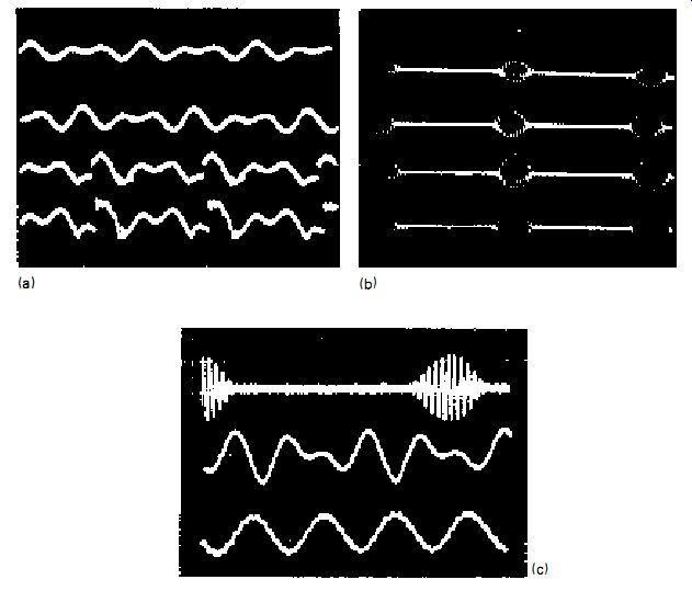
Fig. 5.8: Magnetic pickup tracking oscillograms, (a) mid-frequency, (b)
high-frequency and (c) high, medium and low frequencies. See text for level
details.
To correlate, of course, recording level (velocity) should really be given in meters (m) per second - m/S (the second remains an SI unit but the centimeter - cm - has been changed to m) . Recording level , though, is still expressed in cm/S, which is why we have been using the term! It seems rather silly to say 24x10^ -2m/S instead of 24cm/S. After this discourse, you may thus find the tracking performance of a cartridge stated as 24cm/S peak at 30mN, pulsed high-frequency modulation.
This merely means that a tracking force of approximately 3g is required to track pulsed-high-frequency modulation of 24cm/S peak level . This represents the threshold of tracking, where mistracking would result from an increase in recording level or a decrease in tracking force.
Tracking and Mistracking
The oscillograms in Fig. 5.8 give some illustrations of good tracking and mis-tracking. The two top traces at (a) show good tracking of mid-frequency modulation (1 kHz and 1.5kHz composite signal) at respective levels of 20 and 25cm/S with the pickup tracking at 2g. The next two traces down show severe mistracking when the level is increased to 31.5 and 40cm/S respectively - still with the same tracking force.
Oscillogram (b) shows 10.8kHz pulsed modulation at 15, 19, 24 and 30cm/S from top to bottom, again with the cartridge tracking at 2g. Here is dramatically revealed how the mistracking increases with increase in recording level.
Oscillogram (c) shows a top-flight cartridge tracking at 1.5g 10.8kHz pulsed modulation of 30cm/S (top) , 1kHz/ 1.5kHz modulation of 40cm/S (middle) and 40Hz/4kHz modulation of 30cm/S (bottom) . All levels are peak values. Perfect tracking with no sign of breakup distortion is achieved at all frequencies , which is a reflection of a top quality, though expensive magnetic cartridge.
= = = =