Many different parts are used in radio construction. In order to build a piece of electronic equipment it is necessary to know exactly where each part fits into the circuit.
Circuit Diagram
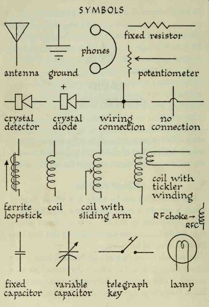
This information can be found in a circuit diagram, which is actually a radio construction plan. Instead of being represented by pictures, parts are shown as symbols. Symbols have been standardized so that they have the same meaning for everyone.
All wires in circuit diagrams are shown as lines. A wire connection is indicated by a heavy dot where lines meet or cross. If no connection is to be made at that point, one line is drawn looped over the other. This system is used in all the circuits shown in this guide. In other types of circuit diagrams connections may be shown by lines that meet or cross; no dots are used.
----------- SYMBOLS
-----------
Capacitors
Capacitors (also known as condensers) are devices that can store an electrical charge. When used in an electronic circuit, a capacitor will charge and discharge current at the same frequency as the current that is applied to it. The amount of current it can handle depends upon its capacity, or capacitance. It will not pass direct current although it will permit the flow of alternating current.
Capacitors are rated in units called farads. Since a farad is much too large for use in radio circuits, capacitance is usually measured in smaller units. A microfarad (abbreviated mf or uF) is one-millionth of a farad; a micro-microfarad (abbreviated mmf) is one-millionth of a microfarad.
Both fixed and variable capacitors are used in radio work. Values of fixed capacitors are either marked on each piece or are shown by color-coded dots. Since there are several different color codes, a confusing situation exists. It is recommended that beginners buy capacitors on which values are clearly shown. Any type of fixed capacitor may be used to construct the circuits described in this guide.
Variable capacitors are used in tuning circuits. They contain two sets of metal plates; one set is fixed and the other is movable. Turning the plates varies the capacitance of the unit. This makes it possible to receive stations at different frequencies. You will need only one capacitor in order to construct the projects in this guide; it should be rated at about 365 mmf.
Resistors
Every conductor offers some opposition or resistance to a flow of current. Copper wire used in radio circuits permits current to flow readily and for our purposes is considered as having no important resistance.
Insulators permit no current to flow through them and are used to block the flow of current completely. Other substances permit a partial flow of current; they may be thought of as partial conductors. Depending upon their composition, they can be made with a specific degree of resistance, so that a certain amount of current will flow through. These are known as resistors. They are used to restrict the flow of current in circuits.
The unit of resistance is an ohm, shown by the Greek letter omega (omega) . One ohm is written as 1 omega. One thousand ohms can be shown as either 1000 ohm or as 1-K (K is the symbol for 1000). Thus 15,000 ohm and 15K represent the same value of resistance. One megohm (commonly called a meg and abbreviated as 1M) is equal to 1 million ohms.
The more resistance a circuit contains, the less current it will pass. It is therefore important to use resistors of the same value as those specified in the circuit you are following. However, the circuits in this guide can be constructed by using resistors of approximately the same value as those indicated. Variations of 25 percent in resistor values will not affect their performance.
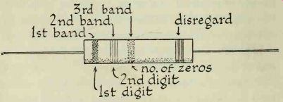
Very few resistors are marked with numerical values; most are color coded. The code consists of bands of color encircling the resistor. Each color represents a digit. If you memorize the color code, you will be able to identify resistor values at once.
In order to determine the value of a resistor hold it as shown in the illustration and refer to the table here.
--------------
--------------
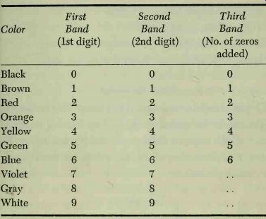
Consider only the first three bands marked on the resistor; disregard the fourth. Let us assume that the resistor we wish to identify is coded as follows : first band, red; second band, green; third band, orange.
According to the table, red has a value of 2, which is the first digit of the resistor value. The second band is green, so the second digit is 5. The third band, orange, shows that three zeros must be added to the two digits we already have; this gives us 25,000.
Here are some other resistor color combinations you can check just for practice:
Brown, orange, yellow: 130,000
Yellow, blue, orange: 46,000
Brown, black, green: 1,000,000, or 1 meg
Orange, green, green: 3,500,000, or 3.5 meg
Potentiometer
A potentiometer is a variable resistor. The amount of resistance in the circuit is changed by turning a control shaft, which moves a sliding arm along a resistance element. Potentiometers, often called pots, are used mostly as volume controls.
-------------
Transistors
Most of the circuits in this guide make use of transistors. Transistors serve the same purpose as vacuum tubes and have several characteristics that make them ideal for our experiments. They are more efficient than tubes, considerably smaller, less expensive, and they will last in definitely. Furthermore, they consume practically no current, and the batteries you use will last a long time.
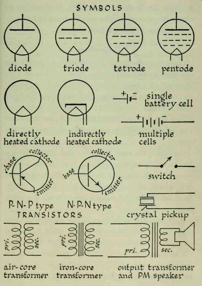
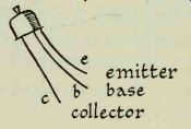
Transistors have three leads which are identified in the illustration as c (collector), b (base), and e (emitter).
Notice the unequal spacing of the leads; the collector is always the one that is farthest away from the other two.
There are two types of transistors: P-N-P and N-P-N.
You can tell which type is indicated on a circuit diagram by carefully observing the arrowhead that represents the emitter. In a P-N-P transistor, the arrowhead points toward the inside of the symbol. In the N-P-N type it points toward the outside. Do not use these types inter changeably. Their elements are connected to the plus and minus battery terminals in different ways. Even a momentary surge of current flowing in the wrong direction can ruin a transistor.
Batteries
The symbol for a single dry cell is two vertical lines. The short line represents the negative terminal, and the long line the positive. The actual voltage used in a circuit can be shown by symbol if it is not too great. Since each cell delivers 1% volts, a power supply consisting of 6 volts would be indicated by four cell symbols. However, it would be impractical to show a 45-volt or 90-volt power supply in this way. For this reason, battery power supplies are generally shown by drawing the symbol for two or three cells; the actual voltage needed is marked on the circuit diagram.
Detector
The detector, or rectifier, is an important part of every radio receiver. In order to understand what a detector does we must first consider what happens at the broad casting studio. When speech or music is picked up by a microphone, varying alternating currents are generated up to about 15,000 cycles per second; these are known as audio frequencies (abbreviated AF). These frequencies are too low to be broadcast directly.
Frequencies of more than 20,000 cycles per second are known as radio frequencies, or RF; high-frequency RF currents can be broadcast easily.
The transmitter at the broadcasting station generates a steady RF current, or carrier. The exact frequency generated depends upon the frequency at which the station is broadcasting. Stations in the broadcast band operate between 550,000 and 1,650,000 cycles per second. For convenience, we shorten these numbers by referring to them as 550 and 1,650 kilocycles; a kilocycle is equal to 1,000 cycles.
The audio and carrier signals are now mixed. The carrier no longer consists of a steady RF current but has the varying audio signal impressed upon it. It is now known as a modulated carrier. This is the electromagnetic wave that is sent out by the broadcasting station.
The modulated carrier is picked up by the antenna of your radio receiver. A tuning circuit separates the desired signal from others, so that it is heard without interference. Now the detector goes to work: it separates the audio from the carrier. The carrier is by-passed, or shunted to one side; it is no longer needed. The audio is amplified and sent along to the headphones or loud speaker, from which it emerges the same as the one that was picked up by the microphone at the studio.
The separation process is known as detection, or de modulation; and the device that does this job is the detector.
A detector act if as a one-way gate, which transforms alternating current into a form of direct current. ( Alternating current reverses its direction periodically, while direct current flows in only one direction. ) Most detectors are made of a substance known as a semiconductor.
Under ordinary conditions, a semiconductor is neither a good conductor nor a good insulator, but it possesses some of the characteristics of each.
There are two types of detectors that we can use. One, a type that has been in use for many years, uses a chunk of galena, a lead ore. This is mounted in a holder. A fine wire "cat's whisker" comprises the other part of the detector. The whisker is touched to different places on the surface of the galena. Some spots are more sensitive than others; it is allowed to rest at that point which produces the loudest signal.
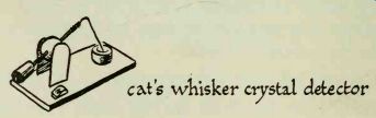
------------- cats whisker crystal detector
Cat's-whisker detectors are not very satisfactory. The slightest movement will disturb the setting of the wire, and a sensitive spot will once again have to be found.
Dirt will impair the sensitivity of the galena, and you will have to be careful not to touch its surface. A fingerprint can leave a film of oil which may put you out of business.
The best type of detector to use is a crystal diode. This is a sealed unit that contains a bit of germanium. It also has a cat's whisker, which is permanently fixed in place so that no tuning is necessary. All you need do is hook the diode into a circuit and it will work automatically.
One end of each diode is marked with a K, a band, or a large dot which indicates the positive or cathode side.
In some circuits the manner in which the diode is connected does not affect its efficiency. In others, reversing the diode connections will improve reception.
Headphones--Headphones are used by all electronics experimenters.
They are more sensitive than loudspeakers and will en able you to hear very weak signals. There are several types of headphones on the market. The most familiar is the one that has two earpieces, connected by a band that slips over your head. There are also single-ear units.
These may be the type that fit over your ear, or they may resemble hearing-aid earpieces which fit into your ear.
Some phones make use of crystals as receiving units.
These will not work in our transistor circuits. Use only magnetic phones.
Impedance is opposition to the flow of alternating current, and is expressed in ohms. The best headphones to use are those that have an impedance of at least 2,000 ohms. These are known as high-impedance phones. The higher the impedance, the more sensitive the phones will be.