All projects in this guide are assembled on a base. The simplest base is a piece of soft pine about 1 inch thick, 8 inches wide, and 12 inches long. These dimensions are approximate and need not be followed exactly.
Circuits can be assembled with little or no soldering by fastening all wires to terminals, which can be made of 5/8-inch or 3/4-inch round-headed wood screws and washers.
To make a terminal, slip a screw through a washer, then turn it part way into the wooden base. The hole in the washer must be smaller than the head of the screw.
In order to fasten two or more wires to a terminal, wrap them once around the screw, under the washer. Turn the screw down to make firm contact against the base.
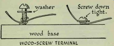
------------ WOOD-SCREW TERMINAL
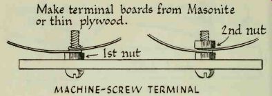
Bases can also be made of either hard Masonite or 1.25-inch plywood. Since both of these materials are too hard to take screws readily, a hole must be drilled wherever a terminal is to be placed, and a small machine screw is passed through the hole.
Machine screws used as terminals should be .5 inch long; you should also have two hexagonal, or hex, nuts to fit each screw. For example, if you are using 0.5-inch x 5-40 machine screws, you must match them with 5-40 hex nuts. Number 5 refers to the thickness of the screw; 40 indicates the number of threads per inch.
To make a machine-screw terminal, first drill a 3/16-inch hole through the base; this will permit a No. 5 screw to go through. Push a screw through the hole from the bottom and thread a nut on it from the other side of the base; tighten the nut. Wires are wrapped once around the screw, after which a second nut is tightened down to hold them firm. Machine-screw terminals are best.
----------- MACHINE-SCREW TERMINAL
You can save yourself the chore of drilling holes by using a piece of Masonite that comes with holes already drilled in it. This perforated Masonite can be purchased at lumber yards and hardware stores.
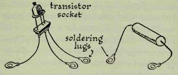
Circuit construction can be simplified to a great degree if you are willing to do some preparatory work. Parts with wire leads can be fastened to terminals very quickly and easily if they are first soldered to soldering lugs. Then, instead of wrapping a wire lead around a terminal, simply place the lug over it. Lugs are made of tinned sheet brass and are inexpensive. Remember to grip all wire leads with long-nosed pliers when soldering them to lugs; this will prevent delicate parts from becoming damaged.
Transistors are particularly sensitive to excessive heat.
Do not solder lugs to transistor leads. The safest way to fasten them into a circuit directly is by wrapping them around terminals.
------------
The best way to install transistors is by using special sockets, as illustrated. The transistor leads are plugged in, making tight contact. Solder a 3-inch length of wire to each socket connection, then solder lugs to the ends of the wires.
Regardless of its size, a single dry cell will deliver 1.5 volts. A large cell can furnish more current than a small one, but that is the only difference between them; their voltage output is the same.
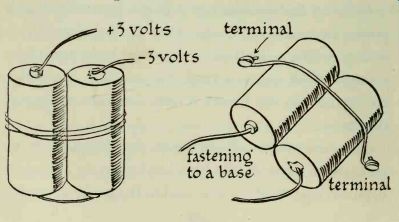
Ordinary flashlight battery cells can be used to supply power for transistor circuits. They can be connected in series, in which case their total voltage is the sum of the voltages of all the cells used. For example, two series connected cells will furnish 3 volts; four cells will supply 6 volts, etc.
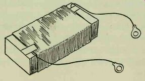
To connect two cells in series, first fasten them together with a couple of rubber bands or wrap them with cellulose tape. Solder a long lead to the positive terminal of the first battery; this represents +3 volts. Solder one end of a short wire to the bottom (negative terminal) of the same battery, and the other end to the positive terminal of the second battery. Another long wire soldered to the bottom of the second battery represents -3 volts.
Any number of cells may be connected in the same way; join the positive of one to the negative of the next, and so on. Manufacturers stack small cells to make batteries capable of delivering high voltage. A 45-volt battery contains 30 cells; batteries with outputs of 67% and 90 volts contain 45 and 60 cells each.
Assemblies of flashlight cells should be strapped to the base by attaching a piece of wire to terminals on both sides, as illustrated. These are not electrical connections; the terminals are simply used as anchor points for the wire strap.
-------------
All large or heavy parts should be secured to the base.
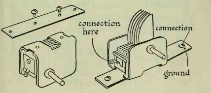
In order to mount the variable capacitor you will need a small piece of sheet metal about 1 inch wide and 2 inches longer than the capacitor. The bottom of the capacitor has two threaded holes which usually take 6-32 machine screws. Do not use screws more than 3/8 inch long or they may interfere with the movement of the capacitor plates. Drill a 3/16 -inch hole near each projecting end of the metal strip and use either wood screws or machine screws to fasten it to the base. The illustration shows how variable capacitors are wired into circuits, and also how they are mounted. The movable plates of a variable capacitor are always connected, or grounded, to the frame. Since the frame is fastened to the metal plate, all capacitor ground connections are made to the plate. Connections to the stationary plates are made to a small lug on the side of the capacitor.
-----------
All large or heavy parts should be secured to the base.
In order to mount the variable capacitor you will need a small piece of sheet metal about 1 inch wide and 2 inches longer than the capacitor. The bottom of the capacitor has two threaded holes which usually take 6-32 machine screws. Do not use screws more than 0.25 inch long or they may interfere with the movement of the capacitor plates. Drill a 3/16-inch hole near each projecting end of the metal strip and use either wood screws or machine screws to fasten it to the base. The illustration shows how variable capacitors are wired into circuits, and also how they are mounted. The movable plates of a variable capacitor are always connected, or grounded, to the frame. Since the frame is fastened to the metal plate, all capacitor ground connections are made to the plate. Connections to the stationary plates are made to a small lug on the side of the capacitor.
Coils consist of turns of wire. Any size magnet wire between No. 24 and No. 32 will do for the projects in this guide. It may have either coated or wrapped insulation. Coils with primary and secondary windings are called transformers. Doorbell transformers and output transformers are wound around laminated iron cores, and are known as iron-core transformers. The iron core of a transformer is shown on circuit diagrams by vertical lines between the primary and secondary windings. The primary is usually on the left side of the symbol, and the secondary is on the right. If the position of the symbol is changed, the primary and secondary will be clearly marked. Both doorbell and output transformers have perforated feet, so that they can be mounted on a base with screws.
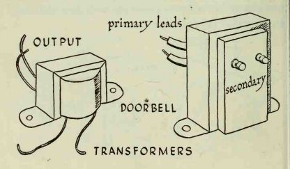
---------- TRANSFORMERS
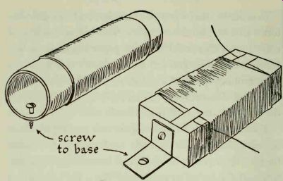
In order to wind a coil you must have a form. Suitable forms can be found very easily. The hollow cardboard cores from either toilet tissue or paper towels make excellent coil forms. You can make a better coil by winding it around a piece of wood about 1 inch thick, 2 inches wide, and 5 inches long; this coil will be used in most of the receivers described in this guide.
The first step is to give the form a coating of Duco cement. This applies to both cardboard and wooden forms. The cement prevents them from absorbing moisture and also serves as insulation. When the cement has dried thoroughly you are ready to start the windings.
Make the first winding 1 inch from the end of the form, and anchor it in place with a strip of adhesive or cellulose tape. Wind about 3 inches of coil, leaving 1 inch of the form exposed; anchor the last turn in place. Leave about 12 inches of wire at each end of the coil, and solder each to a lug. Windings must be tight and close together.
-----------------
----------------
To mount a cardboard-core coil, bore a hole near each end of the form where it will not interfere with the windings. The coil can be fastened to a wooden base with wood screws. If the holes are made to coincide with those in perforated Masonite, the form can be mounted with machine screws.
Wooden coil forms can be mounted in two ways. Drill holes through each end of the form and fasten it to your wooden base with long wood screws. Or, make simple brackets of thin sheet metal, as shown in the illustration.
Screw one side of each bracket to the end of the form, and the other side to the wooden base. Make the brackets long enough to enable you to fasten them to perforated Masonite.
--------------
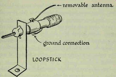
LOOPSTICK
A ferrite loopstick is a commercially made coil which is used in some of the circuits in this guide. It is very sensitive, and very selective when used in a tuned circuit. This coil is not tapped by a sliding arm, as is the wound coil. Instead, it is tuned by varying the position of the ferrite slug (a mineral composition), around which the coil is wound. The coil windings are brought to two terminals. A short wire antenna may be attached to one of them, in which case the other terminal is connected to ground. The wire antenna may be removed, and either connection used as antenna or ground; it makes no difference. Loopsticks are usually furnished with small mounting brackets, together with instructions for installation.
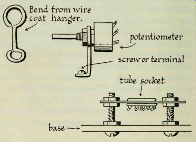
Vacuum-tube sockets should be firmly mounted to the base. When using perforated Masonite or thin plywood, insert two long machine screws from the bottom. Fasten these in place with a hex nut. Screw a second nut to each screw, about 0.25 inch from the top, as illustrated. The screws must be the same distance apart as the mounting holes in the socket so the socket can be slipped over them.
The socket rests on the two hex nuts; a third set of nuts holds it in place.
Potentiometers should be mounted firmly, too. Make a bracket from a piece of wire coat hanger, as shown in the illustration.
--------
The operation of a loudspeaker depends upon the fluctuation of a magnetic field. There are two types of speakers: electrodynamic and permanent magnet. Do not attempt to use an electrodynamic speaker. In the first place, a large supply voltage is required to create the magnetic field needed to operate it; this is impractical. The permanent-magnet type (abbreviated PM) has a powerful alnico magnet built into it. A magnetic field is always present, and high voltage is not needed to energize it. To tell whether your speaker is a dynamic or PM type, hold a screwdriver against the center of its back. If it is a PM speaker, the screwdriver will be strongly attracted to the magnet. An electrodynamic speaker will not attract metal.
Most modern radios use permanent-magnet speakers. They are inexpensive and can be purchased locally at almost all radio shops. If you have a small radio that is no longer needed at home, you can "cannibalize" it by removing parts you need to construct circuits. Almost any speaker can be used, provided it has not been mutilated.
An output transformer is a device that matches the output of an electronic circuit to a loudspeaker. In small radios the output transformer is usually mounted on the speaker frame. Do not try to remove it, or you may dam- age the speaker. Loudspeakers must be handled with care, as their paper cones are quite delicate and can be punctured easily.
You will find four wire leads coming from the output transformer. Two of these are soldered to terminals on the loudspeaker. These are the secondary transformer leads, which are attached to the voice coil, a coil of very fine wire positioned around the magnetic core of the speaker. Electrical energy causes the magnetic field in the voice coil to fluctuate; this makes it move. The movement of the voice coil is transmitted to the entire cone, producing sound. Do not disconnect these leads.
The two leads coming from the other side of the output transformer are the primary leads. One is soldered to a tube socket and the other to the power supply of the radio. Both of these leads can be cut at these points, leaving as much wire as possible attached to the trans former. It is a good idea to extend these wires by soldering about 2 feet of hookup wire to each one. You can then leave the speaker attached to the radio chassis, and even replace it in its cabinet; this will improve its tone quality.
You may not have an old radio that can be taken apart, in which case you will not have a speaker with an output transformer mounted on it. The speaker and transformer will then be bought separately. It will be necessary to identify the primary and secondary leads of the trans former. These are usually color-coded by the manufacturer; primary leads are red and blue, while secondary leads are black and green. It is not necessary to mount the output transformer directly on the speaker. This is done commercially in order to save space. Mount your output transformer in any convenient location on the baseboard and run leads to the speaker, which can be kept some distance away.
In all of our transistor circuits a doorbell transformer may be used as an output transformer, with excellent results. The heavy wire transformer leads are always connected to the primary winding. Two terminals on the other side of the transformer are the secondary-coil connections.
Transformers designed for use with model trains make fine output transformers for transistor circuits. The end that is usually plugged into the house current receptacle is the primary. The secondary winding is the one that is attached to the train tracks. Some train transformers have a control which can be used to change their voltage output. Try the control in different positions to see whether there is any difference in the tone produced in the loudspeaker.