Vacuum tubes perform many functions in electronic circuits. They are used as detectors, amplifiers, and generators of high-frequency currents.
We know that the flow of current in a conductor is caused by the movement of free electrons. At ordinary temperatures the electrons remain within the conductor.
However, as the temperature of the conductor is raised, the velocity, or speed, at which the electrons travel is also increased. If the conductor is heated to incandescence, electrons can actually fly off into space. This is called thermionic emission.
Within some types of vacuum tubes electrons are given off by a thin wire called the filament; these are directly heated tubes. If a filament is heated in air, it will soon disintegrate. It has been found that when emission takes place within a vacuum, the filament will not burn up because no air is present. Consequently, the air is removed from all vacuum tubes.
In other types of tubes the filament heats another metallic surface known as the cathode, which becomes the electron-emitting element; these are indirectly heated tubes. Any surface that gives off electrons within a tube is called the cathode.
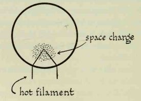
The cathode is connected to a source of current, either directly or indirectly. As current flows through it, it becomes heated so that it glows. Some of the free electrons gain enough energy to fly off into surrounding space. However, they tend to cluster around the cathode in a cloud. These electrons in the vicinity of the cathode form a negative charge; this is called a space charge.
--------------
Particles with similar charges repel each other, and oppositely charged particles attract each other. As new electrons are given off by the cathode, the negative space charge tends to repel the new arrivals, pushing them back on to the surface of the cathode.
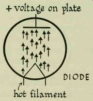
The simplest form of vacuum tube contains two elements. It is known as a diode. In addition to the cathode it has a plate, which is actually a small metal plate.
When a positive charge is placed on the plate, it attracts negatively charged electrons within the tube. Electrons move from the cathode to the plate, causing current to flow.
The moment the positive voltage is removed from the plate, the flow of current stops. If a negative charge is placed on the plate, it will repel electrons and no current will flow.
----------------
----------------
The flow of current within the tube can be increased by raising the plate voltage. The greater the positive charge on the plate, the more electrons it will attract.
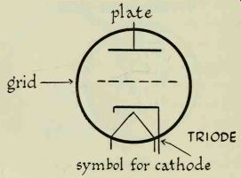
However, the flow of electrons can be controlled more easily by inserting a third element between the cathode and the plate. This is the grid, an open winding of fine wire. A tube that contains a cathode, grid, and plate is called a triode.
The grid acts as an electronic valve that controls the flow of current between the cathode and the plate. In order to function, it must be supplied with either positive or negative voltage.
When the grid has a high negative charge it repels all the electrons emitted by the cathode and does not permit any to get through to the plate; there is no flow of current. As the negative voltage or bias is decreased, more electrons reach the plate and there is an increased flow of current. When the grid is at zero potential (no voltage applied) it has no effect whatsoever; the flow of current between cathode and plate is uninterrupted.
When the grid is positive it helps the plate to attract electrons from the cathode; the current flow is increased.
Up to a certain point an increase in positive grid voltage will result in an increase in plate current.
Thus, the polarity (positive or negative condition) of the grid voltage controls the flow of current within the tube. For this reason it is often called the control grid.
A small variation in grid bias causes a much larger variation in plate current. If we apply a weak signal to the grid, it will be strengthened, appearing as a strong signal at the plate.
This makes it possible to use a vacuum tube as an amplifier in a receiver. The alternating-current RF signal intercepted by the antenna is fed into the grid. It then appears as a greatly amplified signal at the plate.
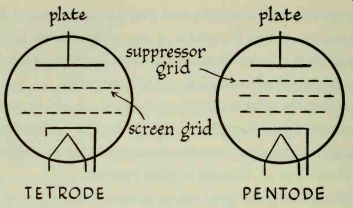
A tetrode is a tube that contains four elements. It has a cathode, a control grid, a plate, and an additional grid called the screen grid, which is located between the control grid and the plate. The screen grid acts as a shield around the control grid. Since it is supplied with positive voltage, it helps draw electrons to the plate.
--------------
Electrons emitted by the cathode travel at great speed.
Some of them strike the plate with enough force to dislodge other electrons, which are thrown into space. Since the screen is positively charged, these secondary electrons are attracted to it. This causes secondary emission, a condition in which a reverse flow of current takes place from plate to screen.
The undesirable effects of secondary emission are overcome by inserting a third grid, the suppressor grid, between the screen and the plate. This suppressor, which is connected to the cathode, acts as a shield and prevents the screen from attracting secondary electrons. These electrons are now forced back to the plate. Tubes that contain five elements (cathode, control grid, screen grid, suppressor grid, and plate) are called pentodes,
A wire is brought from each tube element to a terminal pin in the base. Tubes are made to fit special sockets.
Each type of socket accommodates tubes with a different number of pins. The socket is wired into the circuit, so that tubes can be inserted or removed whenever necessary.
Tube diagrams must be interpreted carefully. The grid nearest the cathode is always the control grid. If a tetrode is shown, the screen is always indicated as a second grid, placed between the; control grid and the plate. In a pentode the suppressor is shown as a third grid placed between the screen and the plate.
Circuit diagrams sometimes show numbers next to the symbol for each element. These numbers refer to the pins at the bottom of each tube. To interpret tube-pin numbers, look at the bottom of the tube. Miniature glass tubes, the type used in this guide, do not have bases.
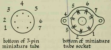
---------------
Instead, the terminal pins are brought directly out of the glass tube envelope. Two pins are spaced wider apart than the others; the one at the left is always pin No. 1.
The other pins are numbered clockwise, from left to right.
Tube socket terminals are numbered in the same way.
Be sure to look at the bottom of the socket.
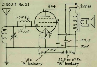
Circuit No. 21
Vacuum-Tube Grid-Leak Detector Receiver--parts needed:
type 3V4 tube
.05 uf fixed capacitor
7-pin miniature tube socket
SPST switch
ferrite loopstick
1.5-volt "A" battery ( filament supply)
variable capacitor
headphones
22.5 volt 0 67.5 volt "B" battery
1- to 5-megohm resistor
100 uuF fixed capacitor
.001 uf fixed capacitor
antenna
ground
------------- Although transistors in many respects are superior to vacuum
tubes, this circuit is included as an example of a simple, easy-to-build vacuum-tube
receiver and to show how a tube works.
You will notice that this circuit does not make use of a crystal-diode detector. Instead, detection takes place in the grid of the tube. The resistor connected to the grid is known as a grid leak. Incoming signal voltage must pass through the grid leak; as it does, some of it is consumed as it forces its way through the high resistance it encounters. This is known as a voltage drop.
As the signal varies, so will the voltage drop across the resistor. This causes the grid voltage to vary. In turn, the plate current varies in step with the changing grid voltage. Since the plate current flows through the head phones where it is converted to sound, it can be seen that the voltage drop across the grid leak is responsible for the receiver's output.
Grid-leak detectors are very sensitive and are good at bringing in weak signals. They ordinarily use resistors of from 1 to 5 megohms. Their chief disadvantage is that they are easily overloaded, or distorted by strong signals.
This condition can be improved to some extent by reducing the size of the grid-leak resistor. While this will cut down overloading, it will also reduce the sensitivity of the circuit.
This receiver should provide fine reception with head phones, but it may not operate a loudspeaker satisfactorily.
A type 3V4 pentode is used as a detector-amplifier. A triode can be used just as well, but the pentode provides an increased gain in signal strength. If you do not have a 3V4 tube, try a 1AE4, 1AF4, 1AJ4, 1L4, 1U4, 1T4, or a 3E5. The 3E5 may be substituted for the 3V4 without any circuit changes. When using the other tubes, a change must be made in the filament wiring. Pin No. 1 will be connected to "A" -f-; pin No. 7 will go to ground; pin No. 5 is not used.
The tube filament is heated by a 1/2-volt power supply.
You can use either 1 flashlight cell or a large 1/2-volt battery. The filament battery is always known as the "A" battery.
Plate voltage is supplied to the tube by a "B" battery, of the type used in portable radios. It may be rated at anywhere from 22/2 to 67K volts.
The negative terminals of the "A" and "B" batteries are connected to one of the switch terminals. The other side of the switch is grounded. When the switch is closed, current will flow in both the A and B (filament and plate) circuits.
Circuit No. 22: One-Tube Regenerative Receiver--parts needed:
type 3V4 tube
100 uuf fixed capacitor
7-pin miniature socket
RF choke
ferrite loopstick with tickler winding
50,000-ohm potentiometer
SPST switch
variable capacitor
1.5 volt «A» battery (filament supply)
loudspeaker and output transformer, or headphones
22.5-volt to 67.5-volt "B" supply
1- to 5-megohm resistor
100,000-ohm resistor antenna
.05 uf fixed capacitor ground
.001 uF fixed capacitor
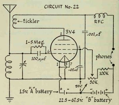
------------ CIRCUIT No. 22
Make a tickler by winding 15 turns of magnet wire directly over the loopstick coil. Fasten the winding in place with a strip of tape. Leave about 12 inches of wire extending from each end of the tickler.
The construction of this circuit is almost identical to that of the preceding one. The only difference is that a tickler coil and a few parts have been added so that the receiver will operate as a regenerative detector.
As in circuits Nos. 15 and 16, regeneration takes place when some of the output voltage is fed back into the input circuit so that it reinforces the input voltage.
The RF choke in the tickler-plate circuit prevents the high-frequency RF alternating current from flowing through the headphones. This current is by-passed to ground through the .001mf capacitor, which provides an easy path.
A 100,000-ohm resistor is shown connected to one end of the potentiometer. Construct your circuit without it. If you cannot control regeneration, put it in.
Hook up the circuit. Place the tube in its socket and close the switch. Tune the variable capacitor with the regeneration control (potentiometer) in different positions. You should hear hissing, squealing, or other signs of oscillation as you tune through stations. If these sounds are not heard, reverse the tickler leads.
Bring in a station with the variable capacitor. Adjust the ferrite slug in the loopstick so that best volume is obtained; leave the slug in this position. Advance the regeneration control until oscillation is heard. Readjust the variable capacitor for greatest volume, then back off the regeneration control until the oscillation just disappears. This is the position for best reception.
Regenerative-detector circuits are very sensitive and are capable of receiving signals over extremely long distances under good conditions.