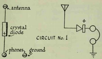
Circuit No. 1:
Simple Crystal-Detector Receiver--parts needed:
type 1N34 crystal diode; antenna; detector, or equivalent; ground; headphones
The simplest radio receiver you can make consists of a crystal detector and a pair of headphones. These should be connected to an antenna and a ground, as shown in the circuit diagram. The accompanying pictorial illustration shows how the actual connections are made.
If you hook up the parts properly you will get radio reception. Several stations may come in at the same time, but this must be expected, since the circuit contains no provision for separating signals. This simply demonstrates that you can build a working radio with very few parts.
-------------
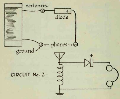
------------- CIRCUIT No. 2
Circuit No. 2:
Crystal-Detector Receiver with Hand-Wound Coil--parts needed:
crystal diode detector; antenna; headphones; ground; hand-wound coil
Let's add a coil to our elementary receiver. There will be an immediate increase in volume. Current developed in the coil is also induced in the windings of the head phones, since they are both connected in parallel. However, we still cannot separate incoming signals; the receiver lacks selectivity.
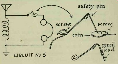
Circuit No. 3:
"Emergency" Crystal-Detector Receiver--parts needed:
safety pin; hand-wound coil; pencil graphite; antenna; coin; ground; headphones
This experimental circuit shows how a radio receiver can be quickly put together in an emergency. The only commercially made part you need is a pair of head phones.
The detector, the most important part of the receiver, can easily be improvised. A "cat's whisker" is made from a safety pin, and any coin can be used instead of galena.
Use pliers to bend the pin so that it barely makes contact with the coin. The illustration shows how the detector is mounted on a baseboard. If you are patient and make the right contact in exactly the right spot, it will work.
You can improve the cat's whisker very easily. Sharpen a pencil, then carefully cut away enough wood to expose 1 inch of lead. Break it off and fasten it to the end of the safety pin with about a dozen turns of bare wire.
-----------
Remove the coin and try several steel objects such as razor and knife blades. You will find that most other metals also make good detectors. Programs can be heard through scraps of aluminum, galvanized iron, brass, copper, and silver. Do not brighten or polish them in any way. The best results will be obtained when the pencil tip rests against a tarnished surface.
The exact pressure exerted by the pencil-tip cat's whisker must be determined by experiment. Bend the safety pin until it just barely makes contact with the metal detector.
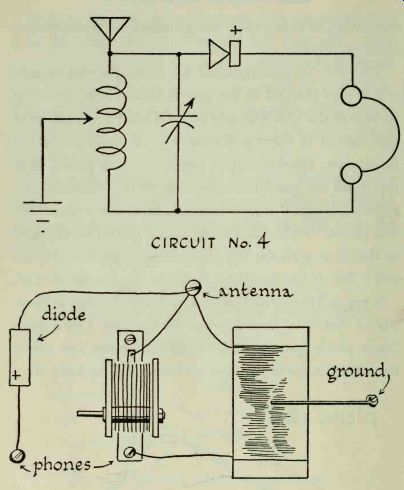
Circuit No. 4:
Crystal-Detector Receiver with Tuned Circuit--parts needed:
crystal diode
variable capacitor (about 365 uuf)
headphones
hand-wound coil
antenna
sliding arm for coil
ground
We have improved the selectivity of circuit No. 3 by adding a variable capacitor. The combination of the capacitor and coil makes a tuned circuit. Varying the capacitance changes the frequency to which the tuned circuit is particularly sensitive. If we vary the coil's characteristics, or inductance, we can make the receiver even more selective.
This can be accomplished by making a sliding arm which taps the coil as the arm is moved across the top surface of the coil. The arm is made from a piece of wire coat hanger or other stiff wire, shaped as shown in the illustration. Bend the wire with a pair of pliers, then scrape all the paint from the ends of the shaped piece, exposing bright metal underneath. Mount one end of the arm on the baseboard. The other end should be adjusted so that it scrapes the top of the coil. Wipe it across the coil a few times, leaving a mark on the insulated wire.
Scrape all the insulation from the coil windings at those places that have been touched by the arm. Use a knife blade, sandpaper, or emery cloth. Move the arm across the coil; it must make firm contact with the bare wire.
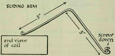
------- SLIDING ARM
------- CIRCUIT No. 4
If it seems loose, remove it from the coil and reshape it with your pliers.
This simple tuned circuit will enable you to separate stations to some degree, but you must not expect perfect selectivity. Nearby stations may create strong interference.
Circuits Nos. 5, 6, 7, 8, 9:
Simple Transistor Hookups--parts needed:
1 transistor, any type
antenna
headphones
ground
Transistors are somewhat like crystal diodes; they are also made of germanium, a semiconductor .

---------- No. 5 - No. 9
Instead of having two leads like a diode, a transistor has three leads. These are identified as the conductor (c), base (b), and emitter (e). Since the transistor is a semi conductor, it will also function as a detector. Simple hookups can be made using a transistor and a pair of headphones; they must be connected to an antenna and ground. Any transistor may be used; both P-N-P and N-P-N types will work. These circuits will deliver varying degrees of volume; try them all.
---------- CIRCUIT No. 10
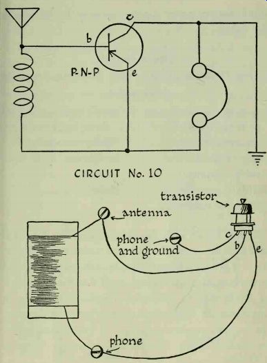
Circuit No. 10:
Single-Transistor Receiver with Hand-Wound Coil--parts needed:
type 2N107 P-N-P transistor, headphones or equivalent; antenna; hand-wound coil; ground
This is the next logical development in the construction of a transistor receiver. Current picked up by the antenna is fed into the coil, which forms a simple, non-variable tuned circuit. The transistor acts as a detector and also amplifies the signal slightly. There should be an increase in volume over circuits Nos. 5 to 9.
None of the circuits described up to this point requires power supplies. No batteries or other source of current has been needed. We have been able to pick up electro magnetic waves with the antenna and convert them into sound. Battery power supplies are used in the circuits that follow.
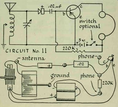
Circuit No. 11 Crystal-Detector Receiver with Transistor Amplifier--parts needed:
type 2N107 P-N-P transistor, SPST (single-pole single or its equivalent throw toggle switch); 1N34 crystal diode; 3-volt power supply; hand-wound coil; headphones; variable capacitor; antenna; .02 uf fixed capacitor; ground 220,000-ohm resistor
In this circuit a single-transistor amplifier has been added to the crystal-detector receiver shown in circuit No. 4. A resistor is also added to limit the current applied to the base of the transistor. An N-P-N transistor such as 2N170 may be substituted for the P-N-P type, in which case the battery leads must be reversed. The transistor acts as a current amplifier and will make reception considerably louder. There should be enough volume to drive a loudspeaker.
------------- CIRCUIT No. 11
When connecting the loudspeaker, remember that the secondary of the output transformer is connected to the voice coil, and the primary leads go to the phone terminals. Not all output transformers will work equally well.
They have different characteristics, depending on the type of tube for which they were originally designed.
Special transformers have been designed for use with transistors, but we are using components that are avail able everywhere. If you have more than one transformer, use the one that provides the loudest signal.
It is important to observe the correct polarity (connections of + and - leads) when hooking up the power supply, or the transistor will be damaged. A 3-volt supply (two flashlight cells in series) will work in this circuit.
The diagram shows a switch, which is convenient but not essential. Just disconnect one of the power supply leads when the set is not in use.
Do not expect the volume of this receiver to be comparable to that of a commercially built radio. Strong local stations will be heard very well, while distant or weak stations will come through with decreased volume. This is an experimental circuit, the purpose of which is to show that a single-transistor amplifier can develop enough power to drive a loudspeaker.
-----------
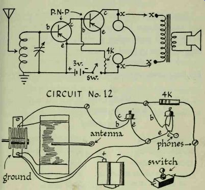
Circuit No. 12:
Two-Transistor Receiver--parts needed:
hand-wound coil
4,000-ohm resistor
variable capacitor
SPST switch
2 type 2N107 P-N-P transistors, or their equivalents
headphones
antenna
3-volt battery power
supply ground
In this circuit the first transistor is used as a detector amplifier. It is coupled directly to the second transistor, which acts as an audio amplifier. In other words, the first transistor not only detects the incoming signal but also amplifies it. The amplified signal is fed from the collector of the first into the base of the second transistor, where it is amplified further. From here it goes to the phones, where the electrical impulses are converted to sound.
Reception will be much louder than that provided by the preceding circuit.
Loudspeaker connections are indicated on the circuit diagram. Use a single-pole single-throw (SPST) switch.
Circuits Nos. 1 to 12 have been shown in both pictorial and diagrammatic form so that beginners can become familiar with construction practices. Experienced radio men never use pictorial illustrations. Anyone who wants to work with electronics must learn to interpret diagrams.
For this reason, only circuit diagrams will now be given.
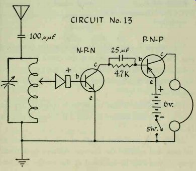
Circuit No. 13:
Two-Transistor Receiver--parts needed:
hand-wound coil
100 uuf fixed capacitor
variable capacitor
25 uf fixed capacitor 1N34 crystal diode headphones type 2N170 N-P-N transistor, 6-volt power supply or its equivalent SPST switch type 2N107 P-N-P transistor, antenna or its equivalent ground 4,700-ohm resistor
The signal is detected by the crystal diode, amplified by the N-P-N transistor and coupled directly to the P-N-P transistor, which acts as a second amplifier. Direct coupling was used in circuit No. 12, but coupling from one P-N-P transistor to another is not too effective. A much greater gain, or increase, in signal strength can be obtained by feeding the signal from an N-P-N transistor into a P-N-P type. Volume should be increased in this circuit, so that a loudspeaker can be used to good advantage. If you do not already know them, refer to other circuits for loudspeaker connections.
---------- CIRCUIT No. 15
Certain precautions must be observed when using both P-N-P and N-P-N type to transistors in the same circuit. They are not interchangeable and can easily be ruined if they are accidentally switched. Also, make it a practice to see that the switch is in the off position before inserting transistors into their sockets.
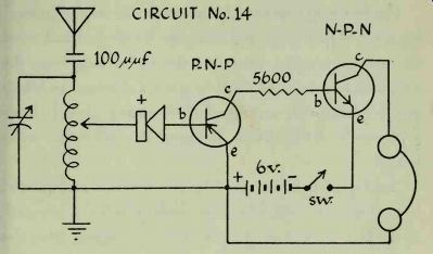
Circuit No. 14:
Two-Transistor Receiver---parts needed:
5,600-ohm resistor
100 uuf fixed capacitor
headphones
6-volt power supply
SPST switch
Antenna
Ground
hand-wound coil
variable capacitor
1N34 crystal diode
2N107 P-N-P transistor, or its equivalent
2N170 N-P-N transistor, or its equivalent
------ CIRCUIT No. 14
This circuit is essentially the same as the preceding one. The only difference is that in this case a P-N-P transistor is used in the first (detector-amplifier ) stage, feeding the signal into an N-P-N type, which is the audio amplifier.
The use of the 100mmf capacitor is optional. Try the receiver with and without it; omit it if it doesn't seem to be needed.
Attach a 3- or 4-foot length of wire instead of an antenna and operate the receiver without an external ground; you may be surprised at the results. For best reception, you will, of course, need both an outside antenna and a proper ground.
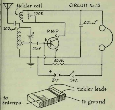
Circuit No. 15:
Single-Transistor Regenerative Detector Receiver--parts needed:
hand-wound coil with tickler winding
.05 uf fixed capacitor
variable capacitor
2N107 P-N-P transistor, or its equivalent
5,000- to 500,000-ohm potentiometer
500,000-ohm resistor
0.001uf fixed capacitor
100 uuf fixed capacitor
headphones
SPST switch
3-volt power supply
antenna
ground
The first step is to modify the coil by adding a "tickler" winding. Remove the coil from the baseboard and wind 15 turns of magnet wire over the coil 0.25 inch from the end that is to be connected to ground. Fasten the winding in place with a strip of tape. Leave 12-inch leads at the ends of the tickler. Refasten the coil to the base board.
The signal is intercepted by the antenna and carried to the tuning circuit, where the desired station is selected.
From here it goes to the transistor. Emerging from the collector, it goes through the tickler coil, which is magnetically coupled to the main coil. Transformer action takes place between the tickler and the large coil. Current flowing in the tickler induces current in the other coil, adding to the incoming signal strength. The strengthened signal is fed into the transistor, and again fed back through the tickler circuit. This feedback cycle is repeated over and over, and is known as regeneration.
If regeneration is unchecked, too much signal energy will be developed and it will "spill over," or oscillate.
Oscillation will be heard as a whistle, buzz, hiss, or other sound distortion. The potentiometer acts as a regeneration control.
----------
Regenerative receivers must be tuned carefully. First tune in a station by adjusting the coil arm and the vari- able capacitor. Move the arm to the point where the loudest signal is heard, and leave it there. From now on all tuning is done with the capacitor. Advance the regeneration control until you hear oscillation sounds. If none are heard, it is a sign that regeneration is not taking place; the tickler leads must be reversed. Final adjustment is accomplished by turning the regeneration control so that it is just below the point of oscillation.
Regenerative receivers are very sensitive to weak signals and provide greater selectivity than many other types.
Circuit No. 16:
Two-Transistor Regenerative Detector Receiver---parts needed:
coil with tickler winding
variable capacitor
1N34 crystal diode
2 type 2N107 P-N-P transistors, or their equivalents
2.05 uF fixed capacitors
500,000-ohm potentiometer
headphones
3-volt power supply
SPST switch
Antenna
ground
This circuit is essentially the same as the preceding one, except that two transistors are used. Volume and selectivity should be increased, so that a speaker can be hooked up with good results.
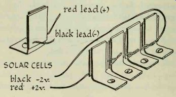
Circuit No. 17:
Solar Battery
Power Supplies
A photocell is a small metal unit, one side of which is coated with selenium. When light strikes the selenium layer it is converted to electrical energy. One type of inexpensive cell may be bought which will produce .5 volt of electricity when exposed to average sunlight. The cell's output voltage is decreased under light of less intensity, so do not expect the same results when it is held under a 100-watt lamp. Other types of cells use silicon or cadmium sulfide instead of selenium.
Photocells (also called sun cells or solar cells) can be used instead of batteries to supply power for any of the transistorized devices shown in this guide. They are rugged and will last indefinitely as they do not wear out.
However, more than one must be used, since .5 volt is not enough to energize a transistor with any degree of efficiency. At least 1.5 to 2 volts is needed.
Cells can be hooked up in series to produce any desired voltage. Each unit has a red (positive) lead and a black (negative) lead. Series connections are made by soldering together the red and black leads of adjoining cells. Four photocells will furnish 2 volts.
When making up a power supply unit, screw the cells to a small base, with the selenium surfaces all facing the same way.
Several transistorized portable radios which are powered by solar batteries have appeared on the market.
These will work anywhere provided there is a light source to which the power pack can be exposed. Since the solar cells have an indefinite life, the power supply is virtually permanent.
Numerous other uses have been found for solar cells, particularly in automatic devices. They are used in traffic control systems, automatic headlight dimming mechanisms, factory-line inspection systems, amusement devices, burglar alarms, door controls, garage door openers, and automatic counters.
-------
------- CIRCUIT No. 18
Photocells are used in photographic exposure meters.
Light is gathered by a lens and concentrated on the cell, which is connected to a sensitive meter. The meter is usually calibrated to show lens-stop openings instead of current.
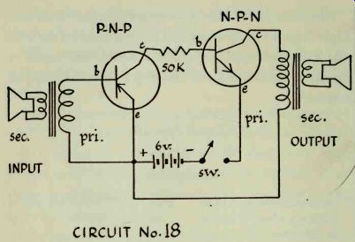
Circuit No. 18:
Sound Amplifier---parts needed:
2 permanent-magnet loud- type 2N170 N-P-N transistor, speakers, about 4 inches or its equivalent in diameter 50,000-ohm resistor 2 output, doorbell or model- 6_voIt power supply train transformers SpsT ^.^ type 2N107 P-N-P transistor, or its equivalent
In this circuit a small permanent-magnet speaker is used instead of a microphone. If you talk into the input speaker, your voice will be heard coming from the output speaker. The amplifier is the same as the one used in circuit No. 14, where it amplified the broadcast signal selected by the tuning circuit. In this circuit it will amplify the sound fed into the input speaker.
This is how the circuit works: When you talk into the input speaker, sound waves generated by your voice cause the cone to move. As the cone moves, it also moves the voice coil, which is centered around a powerful permanent magnet. You will remember that moving a coil through a magnetic field generates electric current.
This current is transferred from the voice coil to the secondary winding of the transformer. Current is induced in the primary and fed into the base of the P-N-P transistor, where it is amplified. It then passes into the base of the N-P-N transistor where it is further amplified, and then through the primary of the output transformer. Current induced in the secondary winding causes the voice coil to move. Since the voice coil is attached to the speaker cone, sound is generated.
Notice that the output transformers are connected in the same way: the secondary windings are connected to the speaker voice coils in both cases; the primary trans former windings go to the circuit.
In this circuit and the next one amplification will take place depending upon the transistors used and the efficiency of the input and output transformers.
Circuit No. 19:
Room-to-Room Communicator--parts needed:
Circuit No. 18 DPDT (double-pole double-throw) switch
The amplifier described in circuit No. 18 can be used as a room-to-room communicator in your home. All you have to do is add a double-pole double-throw switch.
The first step is to connect switch terminals A and C, and B and D, as shown in the diagram. Use insulated wire.
Disconnect the primary transformer lead that goes to the base of the P-N-P transistor, solder a piece of wire to it, and connect it to switch terminal X. Use another wire to connect switch terminal B to the base of the P-N-P transistor.
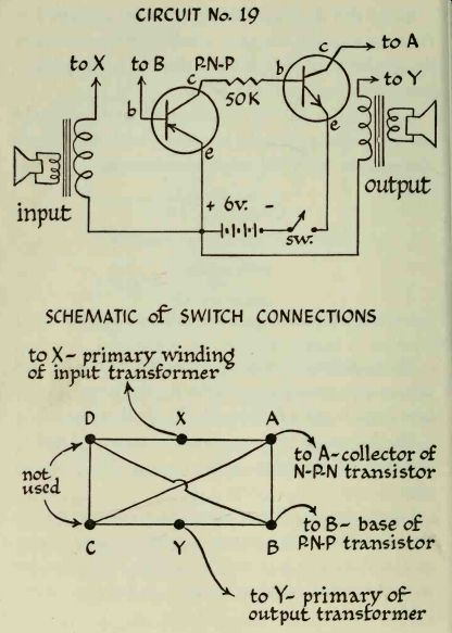
---- SCHEMATIC of SWITCH CONNECTIONS to X-primary winding of input transformer
Disconnect the primary transformer winding that is connected to the collector of the N-P-N transistor, solder a piece of wire to it, and connect it to switch terminal Y.
Connect switch terminal A to the collector of the N-P-N transistor with another wire.
To use the amplifier as a communicator, one speaker and transformer are placed in a remote position. This may be another room or another floor of your house. Two long wires will have to extend from the speaker position to the amplifier. One wire runs between the transformer primary and a terminal on the DPDT switch. The other wire connects the other end of the transformer primary to the positive power supply terminal.
Either speaker may be placed at a distance; it makes no difference. Any wire may be used. However, the switch should be mounted on the baseboard so that it is easily accessible.
When the switch is in one position, one of the speakers is the microphone input and the other is the sound reproducer. When the switch position is reversed, the functions of the speakers will be reversed. The one that was formerly the input speaker will now be in the output circuit. You cannot talk and receive at the same time.
Mark the switch positions so that one is labeled "talk" and the other "receive."
---------- CIRCUIT No. 20
Cigar boxes make good cabinets for both the basic unit and the remote speaker.
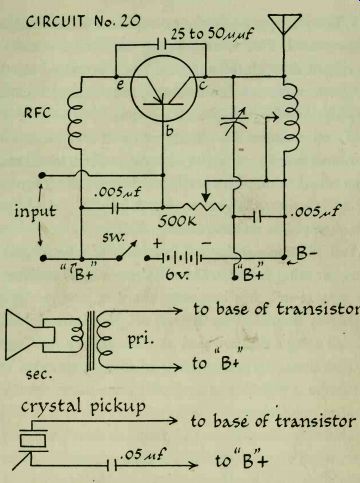
Circuit No. 20:
Wireless Broadcast Oscillator--parts needed:
home-wound coil, or ferrite loopstick
25 to 50 uuF fixed capacitor
2. 005 uF f fixed capacitors
variable capacitor
PM speaker or headphone (s)
P-N-P transistor
SPST switch
500,000-ohm potentiometer
6-volt power supply
RF choke
6-foot wire antenna
This oscillator is a miniature transmitter. It sends out a signal, such as your voice, that can be picked up by any nearby broadcast receiver.
Audio (AF) signals are those which have a frequency of from 15 to about 20,000 cycles. Above 20,000 cycles they are known as radio frequencies, or RF. The oscillator generates an RF signal which falls somewhere between 550 and 1650 kilocycles, the range of the aver age radio receiver. This is the carrier wave, and may be heard in the receiver as a loud hiss.
A permanent-magnet speaker is used as a microphone.
It is connected to the circuit through whatever type of transformer you happen to have at hand. Single or double headphones can also be used as a microphone. Their leads are connected directly to the input of the oscillator.
No transformer is needed.
When you speak into the microphone, an audio signal is generated. This is mixed with the carrier wave and broadcast through the antenna. The transmitted electro magnetic wave now has two components: the RF carrier and the low-frequency audio current.
If you examine the circuit, you will see the familiar combination of a coil and a tuning capacitor, which make up a tuned circuit. This is adjusted to vary the frequency of the transmitted signal so that it may be picked up at different points on the receiver dial.
You will also see that a 6-foot piece of wire is used as a transmitting antenna. Do not connect this oscillator to an outside or other long-wire antenna, or your broad casts may be picked up by your neighbors. Even though we are using a flea-powered transmitter, its range can be extended when it is coupled to an efficient antenna. This would be a violation of Federal Communications Commission regulations.
Almost any transistor can be used in this circuit. However, some may oscillate better than others. If you have more than one, try them all. Remember to reverse the battery leads when using N-P-N types.
Although you can use your home-wound coil, results will be far better if you use a ferrite loopstick, already described.
Construct the circuit and hook up the transmitting antenna. Place the oscillator within a few feet of a radio receiver, and turn them both on. Tune the receiver care fully, listening for the hiss that indicates you are receiving the transmitted signal. Now turn off the oscillator; if the hiss can no longer be heard in the receiver, you may be certain you have picked up the proper signal.
If you cannot pick up the oscillator's signal, try it another way. Set the receiver at an unused portion of the band where there is no station, somewhere near the center of the dial. With the oscillator on, adjust the tuning capacitor until the signal is brought in. If you are using a home-wound coil and you cannot tune in the signal, it may be necessary for you to substitute a ferrite loop stick. This can be tuned by screwing the ferrite slug in and out of position. The sharp tuning circuit formed by the loopstick and variable capacitor should bring in the signal at almost any point on the receiver dial.
Now talk into the microphone; your voice should be heard coming out of the receiver. Adjust the potentiometer to control the volume and clear up any distortion that may be present.
It is most important that you select an unused portion of the receiver band. If there is any incoming signal at that point the oscillator's output will combine with it to produce a third signal, or heterodyne. This will distort your voice; the only way to get rid of a heterodyne is to shift the frequencies of both the oscillator and the receiver.
The circuit contains a radio-frequency choke, marked RFC in the circuit diagram. This is a small coil with fine windings. Its purpose is to restrict the flow of alternating RF currents, while permitting direct current to pass through.
The oscillator can also be used to broadcast phonograph music. You can play records without using an amplifier and have the sound come out of the radio.
However, the arm of your record player must have either a crystal or ceramic pickup cartridge. Magnetic pickup cartridges do not generate enough current.
A shielded wire usually runs from the pickup arm to the amplifier of the record player. This must be disconnected at the amplifier. The inner wire is then connected to the base of the transistor. Solder a wire to the flexible metal wire shield, and connect it to a .05 uf capacitor.
Connect the other end of the capacitor to the "B" plus supply. Turn on the oscillator, and place the pickup arm on a record; the music will be broadcast.