Several problems are encountered when a transition is made from DC to AC circuits. For a given DC circuit the applied voltage usually retains the same polarity, and in many cases it also has the same amplitude. If the voltage does change, the current changes in step with it. Applying AC to a circuit introduces three new problems:
1. The AC voltage periodically reverses polarity.
2. The voltage is continually changing in amplitude.
3. The current and voltage may not always change in step with each other.
When the circuit includes only resistance to oppose the flow of electrons, the AC circuit calculations are not much different from those for DC circuits. When inductance, capacitance, or both are introduced, additional factors must be considered.
Changes of current in inductive or capacitive circuits do not occur in step with changes of applied voltage; therefore the characteristic of phase must be considered. The word phase has several different meanings, but the one used in connection with electrical circuits has to do with current or voltage changes 'with reference to some other change or to some fixed reference.
Let's clarify this definition in order to understand the use of the term more fully. If current and voltage change in step, or synchronization, with each other in an AC circuit, they are said to be in phase. When the changes do not occur in step with each other, the current and voltage are said to be out of phase.
Usually such an expression will also indicate how far out of phase they may be (expressed in some number of degrees), and it may also indicate which is ahead of the other.
A full cycle of AC is considered to occupy 360° of change along a time axis. That is, each cycle can be divided into 360 equal parts of time, during which the voltage or current under goes one complete set of variations. A cycle normally consists of changes from zero to maximum amplitude, back to zero, to maximum amplitude with opposite polarity, and then back to zero again. Each cycle consists of two alternations (or half cycles), one with positive polarity and the other negative.
Each alternation occupies 180° along the time axis.
The term phase can be used to denote the instantaneous position of voltage or current with reference to the complete AC cycle, beginning at zero and ending at 360'. For example, the voltage is at the phase angle of 90°; or, as previously indicated, phase can be used to express a time difference (in terms of degrees) between changes of current and voltage, and it can also be used to express the difference between two currents or between two voltages. These ideas of phase will be further clarified in later portions of the text with reference to particular circuits and circuit conditions.
Vectors are graphical tools which can be used to represent phase relationships. As will be shown more clearly later, the vector not only represents a quantity in a given problem, but it represents an angle or direction as well. In addition to their use with electric circuits, vectors can be used in a variety of other applications-for example, with various types of forces. After reviewing some other ideas relating to alternating current and some ideas relating to angular measurement, we will investigate how vectors can be used in analyzing AC circuits.
SINE WAVES
The basic method of generating an AC voltage is to move a conductor through a magnetic field or to move the field past the conductor. When the motion is in one direction, a voltage of a certain polarity is induced. When the movement is reversed, the polarity of the voltage is also reversed. As an example we can use the simplified diagrams of a generator shown in Figs. 1-1A and 1-1B, correlating its rotation with the sine-wave output of Fig. 1-1C.
In Fig. 1-1A the single loop of wire is in a vertical position as it rotates in the horizontal permanent-magnet field. As it passes through the vertical position, the motion is parallel to the magnetic lines of force, and the induced voltage is zero.
This value of induced voltage corresponds to the zero position of the sine-wave diagram (Fig. 1-1C). As the rotation continues, the induced voltage increases until the loop is as shown in Fig. 1-1B. At this instant, the motion of the loop is perpendicular to the direction of the lines of force so that maxi mum voltage is induced. This voltage corresponds to the 90° position on the sine wave with the polarity of the output voltage as indicated on the coil leads.
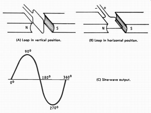
Fig. 1.1. Simplified diagrams of a generator and its sine-wave output. (A)
Loop in vertical position. (B) Loop in horizontal position. (C) Sine-wave output.
The voltage decreases to zero when the coil once again reaches the vertical plane. This corresponds to 180°; however, even though the coil is vertical, the leads have been reversed from the position at 0°. On the next quarter-turn the coil produces maximum voltage as it reaches the horizontal plane. But the leads are reversed from the positions shown in Fig. 1-1B so that the output is maximum, but with opposite polarity. This is the 270° point on the sine wave. After another quarter-turn the cycle is completed.
The basic waveform produced by the generator is that of a sine wave, which is also the basic waveform on which all others are based. A sine wave is one that follows a specific set of variations, those of the sine, a trigonometric function. That is, the amplitude of the wave at any point is proportional to the sine of that particular angle. By multiplying the maximum value of the voltage or current by the sine of the angle, the actual voltage at that instant can be determined. There are many, many different sets of possible variations, but the sine wave is a specific one, and has exactly the same shape in every instance. Notice also that the rise in voltage in Fig. 1-1C is not linear; for example, half of the maximum amplitude occurs at 30° in the cycle, but it requires 60° to rise the other half. Maxi mum voltage is reached at 90°, after which the drop in voltage is symmetrical to the rise which preceded it. In 60° the voltage drops to half the maximum; then only 30° are required in which to drop the remaining half, decreasing to zero at 180°. One half of a sine wave does not have the shape of a half circle, as is sometimes depicted in printed matter. Nor are there any straight-line portions, even though the curve comes more nearly to a straight line each time it passes through zero amplitude. This has to do with the rate of change of the waveform on which the phase difference sometimes depends.
The rate of change is not linear at any point, but it is continually changing. Maximum rate of change (or slope) occurs each time the wave passes through 0° or 180°; that is, the change of voltage per unit of time is greatest at these points.
The rate of change is minimum at the maximum-amplitude points on the curve, 90° and 270°. At these points the rate of change is zero because the wave reverses direction at these points. From 270° on one cycle to 90° on the next the voltage is changing from maximum negative to maximum positive.
Mathematically this is a positive slope, or rate of change.
From 90° to 270° within the same cycle there is a negative slope, or rate of change as the voltage goes from maximum positive to maximum negative. These are important points in analyzing how inductance and capacitance act in AC circuits.
There are other characteristics of sine waves which are also important in analyzing AC circuit action. One of these is Frequency. If the speed of rotation of the coil in Fig. 1-1A were increased, more sine waves would be produced in any given unit of time. Frequency of an AC wave is defined as the number of cycles that occur during one second of operation, hence the basic unit is cycles per second (cps). If more cycles are produced each second, the time duration of each single cycle is de- creased proportionally. Frequency and time are inversely proportional as shown by the relationships: t = f = - 1 where, frequency is in cycles per second, time is in seconds.
For example, with a 60-hz waveform each cycle has a time duration of 1/60 second. But if the frequency were doubled, the time of each cycle would be halved. However, each cycle is still divided into 360°, regardless of the time required for the cycle to occur. When frequency is increased, each degree rep resents a smaller unit of time, and vice versa. In some cases the time duration of a cycle is referred to as its period.
The average amplitude of a sine wave is zero because the positive alternation is exactly like the negative, except for polarity. This does not mean that there is zero voltage, al though a DC voltmeter might indicate zero. It only means that the average amplitude over a full cycle is zero. Average amplitude of any one alternation is 0.636 of the peak (maximum) value. The effective value of an alternation is the square root of the average of the instantaneous values and is also called the root-mean-square value (rms). Numerically, the rms value is equal to 0.707 of the peak value of the wave.
The instantaneous value (the amplitude at any instant of time) can be determined by multiplying the peak value of the wave by the sine of the angle for that instant of time. And finally, the peak value may be determined by multiplying the rms value by 1.41, or the average value of one alternation by 1.57. It should be stressed, however, that these relationships are true only for sine waves and not for any other wave shape that might occur. Also, these relationships are for sine waves at any frequency.
In some cases the peak-to-peak value of a signal may be of interest. This is the total voltage swing, from maximum positive to maximum negative (or vice versa), and it is equal to twice the peak value of an alternation. This relationship is generally true regardless of the waveshape of the signal in question. All these relationships and the conversion factors are summarized in Table 1-1.
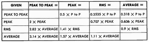
Table 1-1 Voltage Relationships and Conversion Factors
As previously stated for an AC circuit having a resistive load, the current and voltage are in phase with each other.
That is, the changes of waveform occur in step, even though the amplitudes and units of measurement are different. This condition is illustrated in Fig. 1-2A. When reactive components (L or C) are also included in the circuit, the current and voltage are out of phase by some number of degrees. For an inductive circuit the voltage peaks occur ahead of the current peaks (Fig. 1-2B) because inductance tends to oppose a change of current.
Using voltage as the reference, current is said to be lagging the voltage. With capacitive circuits the opposite conditions hold true, and current leads the voltage. If the labeling of the wave forms in Fig. 1-2B were reversed, it would represent a capacitive circuit. In the remainder of this SECTION it will be shown how these phasing conditions are caused.
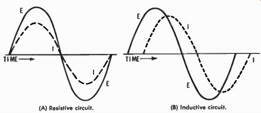
Fig. 1-2. Voltage and current phase relationships in resistive and inductive
circuits. (A) Resistive circuit. (B) Inductive circuit.
The term phase angle (usually 0) represents the angular difference between current and voltage; it may also be referred to as phase difference. However, before proceeding, several possible causes for confusion should be pointed out. First, notice the relationships in Fig. 1-2B. The horizontal axis is calibrated in terms of time; thus, as shown, the positive peak of voltage occurs at an earlier time than the positive peak of current. So voltage is leading the current, or conversely, cur rent is lagging the voltage. The confusion here arises because, when looking at the waveforms, the current seems to be out ahead of the voltage. Erroneous results are obtained from this type of analogy. And a final warning, the term phase has meaning only when the frequencies of the waveforms being compared are the same. Otherwise, the time differences are continually changing, and a phase condition cannot be stated definitely. When frequencies are the same, the time difference, and thus the phase angle, are the same at any points of comparison. If the relative phases were shifting, even though the frequencies were still the same, it would be equally difficult to state a definite phase relationship.
INDUCTIVE CIRCUITS
A coil of wire has the tendency to oppose any change of current through it. This occurs because the coil builds up a counter-electromotive force (CEMF) in opposition to the applied voltage. Opposing a change of current means that if there is no current through the coil, there is opposition in trying to start a current. But if there is current already flowing, the tendency of the coil is to keep that current flowing, even though the excitation voltage may have been removed. Also, a coil opposes any existing increase, or decrease, of current.
The CEMF is built up only during the time when the current through the coil is changing in value. The actual voltage induced is directly proportional to the rate of change of the current. When DC is applied, the current builds up to the maximum value some time after the voltage is applied. At the first instant the voltage is applied current is zero, since the CEMF equals the applied voltage. Total voltage affecting the circuit at any instant is the applied voltage minus the CEMF. So when the latter is high, the total circuit voltage is low, causing low current. As the applied voltage stops changing in value, the induced CEMF decreases, allowing the current to increase to a higher value. The current increases at an exponential rate, as shown in Fig. 1-3.
The time required for the current to increase in an inductance is determined by the ratio of inductance (L) to the resistance (R) of the coil.
TC = L li where,
TC is the time constant in seconds, L is the inductance in henrys, R is the resistance in ohms.
During one time constant the current increases to approximately 63.2% of the maximum value. In the next time constant the current increases by 63.2% of the remaining change (63.2% of 36.8% --- 23.3% ). So at the end of the second time constant the current has increased to 63.2% plus 23.3%, or 86.5%, of the maximum value obtainable. Theoretically the current never reaches 100% of the maximum possible value, but in a practical sense it can be assumed that the maximum is reached in five time constants. The percentage at the end of each time constant is given in Table 1-2, using only the left side. During each time constant the current changes by 63.2% of the remaining possible change.
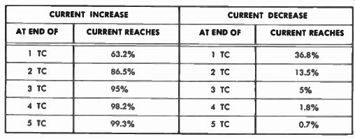
Table 1-2 --- Percentages of Current Increase and Decrease at the End of Each
Time Constant.
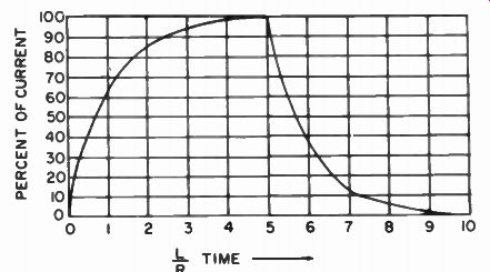
Fig. 1-3. Current increases exponentially in an inductive circuit.
As an example, suppose that a particular coil has an inductance of 10 henrys and a resistance of 100 ohms.
10 TC = = 0.1 second 100
If the applied voltage is 100 volts, at 0.1 second after the DC voltage is applied the current increases to 63.2% of the maximum value.
100V 1 ampere
Maximum current = 100n
So at the end of one time constant the current is 63.2% of 1 ampere, or 0.632 ampere. At the end of the second time constant the current will rise to 0.865 ampere, etc., until the maximum is approximately reached at the end of five time constants. Notice that at that time the actual current is 0.993 ampere, which is maximum for all practical purposes. And even if the time were extended to ten time constants, the additional rise would be only a very small amount.
If, after the current has reached maximum, the applied voltage were disconnected, a CEMF would again be induced. But this time the polarity of the CEMF is opposite, but again opposing a change of current. The tendency here is to keep the current flowing, but since the CEMF cannot remain in definitely, the net result is that the current is delayed in its de crease to zero. The rate of decrease is the same as the rate of increase, and the actual time involved depends on the L/R time constant. Referring to Table 1-2 (the right side), it can be seen that at the end of 1 time constant of decrease the cur rent has dropped 63.2% of the total amount of which the drop can be. Therefore, at the end of 1 time constant the current has decreased to 36.8% of the maximum value. Then, the current drops to zero, for all practical purposes, at the end of five time constants.
For purposes of using vectors and phase, one important point from this explanation can be learned. That is, in an inductive circuit current changes lag voltage changes by some amount of time. The current changes after the voltage does, or we can say simply that current lags voltage. Or, if you prefer, we could say that voltage is leading the current.
With DC applied the time of lag is determined by the L/R time. However, with an AC sine-wave input to a pure inductance the angle of lag is always 90°, as indicated in Fig. 1-4.
This lag of 90° holds for any frequency. The actual lag time is inversely proportional to the frequency. For example, if the frequency is increased, the time duration of each cycle is decreased so that the lag time is also decreased, even though it is still 90° of the operating frequency.
Any practical circuit also contains resistance in which the current and voltage are in phase with each other. In an LR circuit the actual phase angle is always less than 90° but greater than 0°; the actual amount depends on the relative values of the circuit components. This also means that any calculations involving an inductive circuit must consider the phase in order to obtain a correct solution.
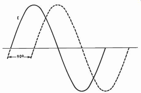
Fig. 1-4. The angle of lag in a pure inductance circuit is always 90°.
The opposition that inductance exhibits in an AC circuit is called inductive reactance ( XL) and can be determined by:
XL = 2 pi fL
where,
XL is the inductive reactance in ohms, f is the frequency in cycles per second, L is the inductance in henrys.
This means that circuit opposition is directly proportional to operating frequency and also to inductance. If either, or both, are increased, the inductive reactance is also increased.
XL, however, acts at 90° with reference to resistance so that XL and R cannot be added arithmetically, for example in a series circuit. They must be added vectorially, which creates another need for a knowledge of vectors and phase for AC circuit calculations. These vectorial methods are investigated in later SECTIONs.
(A) Charge. (B) Discharge.
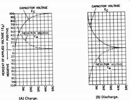
Fig. 1-5. Charge and discharge curves of an RC circuit.
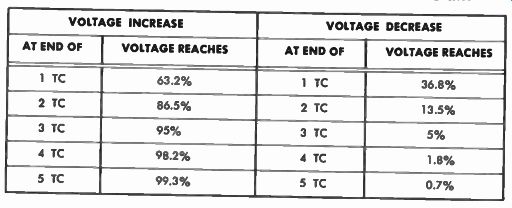
Table 1-3 Percentage of Voltage Increase and Decrease Across a Capacitor at
the End of Each Time Constant
CAPACITIVE CIRCUITS
A capacitor has the tendency to oppose any change of voltage across it, and in some ways it can be said to act oppositely from inductance. If a DC voltage is applied to a capacitive circuit, the current through the circuit is maximum at the first instant, but there is zero voltage across the capacitor. Then the capacitor accepts voltage at an exponential rate. As the voltage across the capacitor increases, it opposes the applied voltage, causing current to decrease. As soon as the voltage across the capacitor equals the applied voltage, the circuit current is de creased to zero. The rise in capacitor voltage is at the same exponential rate as the rise in current in an inductive circuit.
Then if the applied voltage is cut off, the capacitor acts as a source of voltage, creating maximum current at the first instant. As the capacitor loses voltage at the exponential rate the current decreases at the same rate until both reach zero.
These changes are shown in graphic form in Fig. 1-5.
The time required for these changes to occur is determined by the values of resistance R and capacitance C in the circuit.
TC=R xC
where, TC is the time constant in seconds, R is the resistance in ohms, C is the capacitance in farads.
Just as with inductance, the time constant is the time required for 63.2% of the total change to occur. For a series RC circuit the voltage across the capacitor rises to 63.2% of the applied voltage during one time constant. During the same time the current decreases to 36.8% of the maximum value.
Other values are given in Table 1-3, and just as with inductance the total change for all practical purposes is assumed to occur in the time of five time constants. Also shown in this Table are the percentages of capacitor voltage and current for each time constant of capacitor discharge.
These actions show that, for a capacitor, the current occurs ahead of the voltage. The time difference is determined by the product of R and C. Therefore, for a capacitive circuit the current leads the voltage. When a sine wave of voltage is applied, instead of DC, the phase angle between current and voltage is 90°, assuming that circuit resistance is zero. This 90° phase difference holds for any frequency, and the time represented by the 90° is one-fourth of the time of one cycle at the operating frequency. For example, if frequency were in creased, 90° of a cycle would represent a shorter period of time.
In a practical circuit containing R and C the phase angle is less than 90° but greater than 0°, depending on the relative circuit values. The opposition offered by the capacitor is capacitive reactance (Xe) and can be determined by:
1 Xe &IC
where, Xe is the capacitive reactance in ohms, f is the frequency in cycles per second, C is the capacitance in farads.
The reactance is inversely proportional to both the Frequency and the capacitance. If, for example, either, or both, were increased, the capacitive reactance would decrease. Xc acts at an angle of 90° as compared to R; therefore in any RC circuit calculation the phase must be considered. But with a capacitor the current leads the voltage by 90° ; whereas with an inductor the current lags by 90°. This means that inductive and capacitive currents are 180° out of phase with each other.
And, as will be seen later, in some circuits their effects directly oppose each other. A combination RCL circuit brings in other uses of vectors and phase.
Harmonics are whole-number multiples of some fundamental frequency, and any waveshape other than a sine wave is composed of a number of sine waves at different frequencies, phases, and amplitudes. For example, a square wave is composed of a fundamental sine wave plus sine-wave components at odd-number multiples of the fundamental frequency. The fundamental in any wave is the lowest frequency contained and is also called the first harmonic. Two times the fundamental is the second harmonic frequency, etc. In music these harmonics are often referred to as overtones.
With regard to phasing, the complex waveshapes introduce additional problems because the actual time of lead or lag is different for each frequency. This is caused by two things.
First, 90° of a cycle represents a different time duration for every frequency, decreasing as frequency is increased. Second, the values of X1 , and Xe vary with frequency. This changes the magnitude of the phase angle, giving a different number of degrees of lead or lag for each separate frequency.
With this brief review of reactive circuits we have shown how the different phases originate, and why vectors and phase must be considered to be extremely valuable tools in solving or analyzing AC circuits. Subsequent SECTIONs pursue the subject further, covering the various phase and vectorial methods needed.
QUIZ
1. How many degrees are contained in a complete cycle of rotation?
2. A vector rotates two and a quarter revolutions. How many degrees does this include?
3. A signal has a frequency of 500 cps. What is the time duration of each cycle?
4. If a signal has a period of 0.05 second, what is its frequency?
5. The rms value of a sine wave is 100 volts. What is the peak value? What is the peak-to-peak value?
6. An AC signal has a peak amplitude of 250 volts. What is the rms value? What is the average value of a single alternation?
7. By what factor would peak-to-peak voltage be multiplied in order to determine rms voltage?
8. An RL series circuit includes an inductance of 5 henrys and a resistance of 200 ohms. What is the time constant?
9. In this same circuit the peak current is 2 amperes. What is the current at the end of three time constants after a DC voltage is applied?
10. Will a coil discharge its field faster with a short across it or with its terminals open-circuited?
11. A 0.5-mfd capacitor is connected in series with 60,000 ohms. What is the time constant?
12. If a DC voltage of 200 volts is applied, what is the capacitor voltage after one time constant of charge?