THE basic meter in all volt-ohm-meters is the well known moving coil or d'Arsonval type movement, named after the French physicist Jacques Arsene d'Arsonval. As early as 1882, this scientist made an instrument which he called a "reflecting galvanometer." Instead of a pointer, the instrument had a small mirror attached to its coil. The mirror reflected a beam of light and, as the coil and mirror turned, the reflected beam turned with it. A scale mounted at some distance from the mirror showed a spot of light traveling from one position to another. The amount of travel indicated the rotation of the coil and, therefore, the current through it.
The first question we can ask of course is, "What makes the coil rotate?" Let us begin with magnets. Magnets have two poles, North and South, named after the poles of the earth. Two poles which are alike-the North poles of two magnets, for example repel each other, and two poles which are opposite, a North and a South, attract each other.
We have learned by experience (we cannot really explain it) that when we pass an electric current through a coil of wire, the coil becomes a temporary magnet with a North and a South pole.
If we suspend such a coil (on pivots) in a magnetic field (supplied by a permanent magnet) the coil (Fig. 101) will tend to rotate when we pass a current through it. The temporary North pole is attracted to the South pole of the permanent magnet and repelled by its North pole. The opposite happens to the temporary South pole. If we make the coil turn against a spring, the spring will resist more as we rotate the coil. To make the coil turn more we must send a stronger current through it, creating greater attraction and repulsion forces in the field.
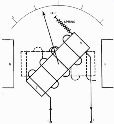
Fig. 101. The principle of the d'Arsonval meter is a rotating coil in a magnetic
field. The coil is wound on a rectangular-shaped aluminum bobbin mounted between
the poles of a permanent magnet. The meter works be cause of the forces of
attraction or repulsion between magnetic poles.
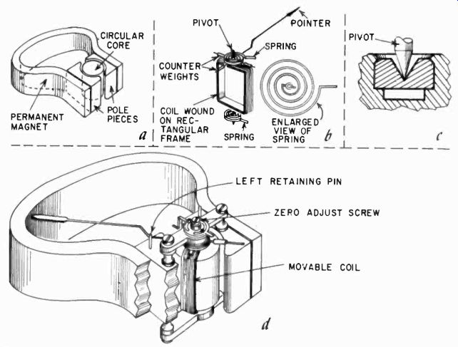
Fig. 102. Interior view and construction details of the moving-coil meter.
A well-constructed meter is a precision instrument. The internal resistance
of the meter is the dc resistance of the coil wound on the bobbin.
Thus, the coil's rotation is directly proportional to the current through it for a given magnetic field strength. When we turn off the current, the coil, pulled back by the spring, will resume its original position. If we were to reverse the current, the coil would rotate in the opposite direction. Thus we must always make sure the current in a d'Arsonval meter goes in only one direction, so that the pointer will deflect to the right, and not to the left.
It takes a lot of refinements to make a d'Arsonval movement from the crude idea of Fig. 101, but the principle is all there. One refinement is that we make the field of the magnet in which the coil rotates as uniform as possible. This is done by shaping the pole pieces so that the coil can rotate just inside of them. The space between the poles contains a soft-iron cylinder, which just allows the coil to rotate around it. This is shown in Fig. 102-a.
This homogeneity or "sameness" of the field assures that the contribution of the magnetic field to the rotation of the coil is always exactly the same, making the rotation the indication of the amount of current in the coil only. (Sometimes, for special reasons, this is not done, but in VOM's we always have "linear" meters.) The coil is mounted on small shafts which are supported in jewel bearings (see Figs. 102-b and-c). The springs are two small bronze spirals which are also used to carry the current to the coil.
To be useful, the coil must have a pointer. The longer the pointer is, the easier it is to read the rotation of the coil. Theoretically, we can make the coil itself perfectly symmetrical, and it would make no difference in which position we used it. But with the long pointer attached to it, the meter would tend to deflect simply from the weight of the pointer. We could counteract this by using strong springs, but then the meter would show a different reading for the same current, when held with the face horizontal or vertical. In one case, gravity would not help, and in the second case it would.
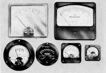
Fig. 103. Basic meters we available in many sizes and shapes.
As an indication of size, the unit shown at the top left is a 1-1/2-inch rectangular type; that at the bottom left is a 3-inch round while the one at the bottom right is 1-5/16-inches square.
The only alternative is to counterbalance the weight of the pointer so that the meter will show exactly the same deflection for the same current in all positions. We do this with little weights on a cross-arm, shown in Fig. 102-b. By positioning these small weights for exact balancing, we can make the meter read precisely the same in all positions, even upside down.
The magnetic field created in any coil is proportional to the current through it and to the number of turns in the coil; this is what we call ampere turns. If we wind more turns on the coil bobbin, it will take less current to get the same amount of coil rotation or pointer deflection. With more turns in the coil, the meter will be more sensitive. The coil is made with very thin wire, and this wire has quite a bit of resistance. Sensitive meters have a higher coil resistance. We call this internal resistance to avoid confusion with other resistances we will use with meters.
Instruments can be selected for their sensitivity. But we must remember that one thing does not change much from meter to meter and that is the friction in the bearings. For very sensitive meters, the bearings must be more precise, reducing the friction.
Some meter bearings are as accurate as and have the same quality as watch bearings, making the meters. very expensive and also quite delicate.
Meters may also be selected for their size. Fig. 103 shows some of those available. The larger the meter, the longer the pointer, and thus the easier it is to read accurately. But, again, when we have a long pointer, a relatively small force could bend it, and the large meters are, therefore, more delicate than the smaller ones.
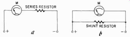
Fig. 104. To measure voltage (a) we use a series resistor to reduce the amount
of current flowing through the meter coil. To measure a large current (more
than can be permitted to pass through the meter) we shunt part of it through
a resistor in parallel with the mete? (b). Series and shunt resistors are changed
by a rangy switch on the front of the VOM.
Even if you buy a factory-made instrument, you will be concerned with the sensitivity of the meter in it, for the resistance of the unit (which will "load" the source you are measuring) will be a function of the sensitivity of the meter.
Why we use external resistances Deflection is proportional to the current through the coil, and only the current. As a meter, then, it can measure only current, and only as much current as will deflect the pointer the entire scale length. This is a very limited amount at best. Should we want to measure voltage, we will have to measure the current this voltage creates in the coil. Usually this will be much more than the coil can handle. The pointer will bend against its stop, and eventually the coil would get hot and burn. We can reduce the current by putting an external resistance in series with the coil, thus reducing the current according to Ohm's law. The more sensitive an instrument is, the more resistance it will need externally. We will discuss in the next section how much resistance to use.
Let us look at another way to reduce the current in the meter coil. When we were interested in measuring voltage, it did not matter exactly what the current was so long as it was proportional to the voltage, and we could read the deflection of the pointer on the scale as voltage. But suppose we want to measure current of a greater magnitude than the meter coil can handle. We might get another meter, but there is a simpler way. We can let only a part of the current go through the meter, and the other part we send through a resistor. This resistor, which we call a shunt, must be in parallel with the meter. With a shunt, we can make any moving-coil meter capable of "reading" a larger current than its coil can handle. Fig. 104 shows the two basic situations schematically.
Accuracy of the meter
There are several kinds of accuracy with which we are concerned. Some of these are inherent in the basic meter. The first of these is what is called "repeatability," meaning that the meter shows exactly the same deflection for the same kind of current.
This depends on the smoothness of the bearings and other mechanical features, such as the springs, etc. Repeatability is a built-in characteristic and is generally quite good. Full-scale repeatability accuracy of a meter is often within 1%.
Next, if we consider the factors which determine deflection, you can see that if the magnets in meters vary a little bit in their strength, the meters will also vary a little bit in their indication of current. Thus, here is another item of accuracy, which we call calibration accuracy. For example, a 50-microampere instrument may actually deflect full scale with only 48 pa. There are two ways to do something about this kind of accuracy. In the example mentioned, we could supply the meter with a new scale, which reads 48 microamperes full scale. Or we could shunt the meter with a resistance of such a value that, when the meter reads 50 pa, 50 pa is actually going through the combination of meter and shunt. Both methods are used to provide calibration accuracy for meters, although the latter is more often used commercially.
In a volt-ohm-meter, calibration accuracy will be a function, not only of the meter itself, but also of all the external resistances used with it. The more accurate our resistances, the greater the calibration accuracy. This is something which we can control.
Why and how we change meter scales
One reason for changing meter scales was mentioned-changing calibration. Meters are basically current-measuring instruments, and so their scales are made to read current in microamperes, milliamperes or amperes. But suppose we want to read voltage only. It would then be much more convenient to have a scale reading in volts. What's more, frequently we like to read voltage in steps of 3 to 1, in other words, as 1 volt, 3 volts, 10 volts, 30 volts and so on. In that case, we would need at least two scales, one with a number of divisions which is a multiple of 10, and one with a number of divisions which is a multiple of 3.
New scales for meters can be made in many ways. You can draw them on paper and paste them over the old scale. Or you can make them photographically. You can even buy meter scales and decals to make new scales. Whichever way the scale is made, to install it, the meter must be opened up, the existing scale removed, modified or replaced.
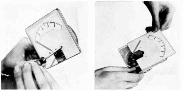
Fig. 105. The meter face is generally fastened to the meter movement by two
small machine screws. These are being removed as shown at the left. After the
screws have been taken out, slide (do not lift) the meter face out as shown
in the photo at the right. This job must be done carefully or the meter pointer
will be bent.
This is a rather delicate job. First, you must remove the screws that hold the movement in its case. Do this only on a bench which is spotlessly clean, for particles of dirt or dust which get into the movement are extremely hard to clean out. Worse, if there are any iron particles about, they will be attracted to the magnet and become almost impossible to remove.
After the movement is out of the case or, in some meters, after the cover is removed, the next step is to take out the two screws that hold the meter scale in place. The scale is usually a thin sheet of brass with the scale printed on it. Next, carefully slide out the scale, and do whatever modification you need to do on it. The last two steps are shown in Fig. 105.
After changing the scale, the whole thing has to be put together again. This is delicate work, for the pointers in meters are made from a very thin piece of aluminum, not much thicker than foil, and are easy to bend. Once' bent, they are very difficult to straighten, partly because the cross-section of a pointer is not flat, but curved for strength. So be very careful with the pointer.
When you work on a plastic-front meter (Fig. 105) be very careful not to scratch the front face; scratches will mar the meter permanently, for there is no good way to remove them.
Since the need to change scales on meters is so common, one manufacturer has designed a meter on which the scale and face can be changed easily. The same scale can be used with different movements or, the same movement with different scales (Fig. 106).
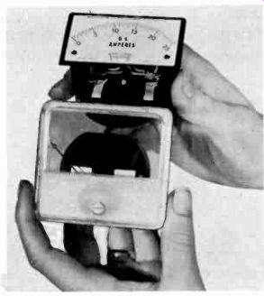
Fig. 106. This meter is designed for easy interchangeability of scales. (Triplett
Electrical Instrument Co.)
Sometimes you may need several scales at once, depending on the ranges you choose. The selection of the proper scales with the choice of accessory resistors will be discussed in Section 2.
Here, in Fig. 107, we show some of the scales you might have to use. The divisions in the 3, 30 and 150 scales are multiples of 3; in the 1, 5, 500 scales, multiples of 5. The logarithmic scale is used for decibels, which is a logarithmic function and which we will later discuss in detail.
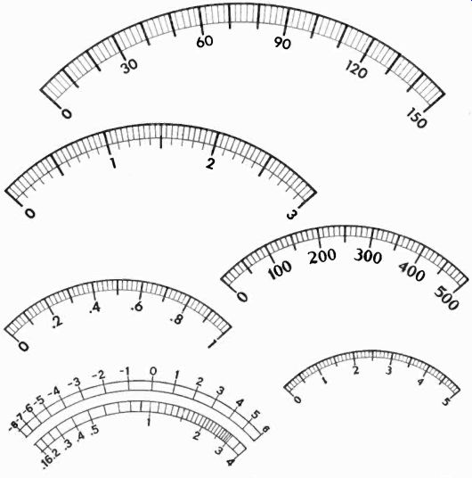
Fig. 107. Representative types of scales used with the VOM. These fall into
three different categories: linear, nonlinear and logarithmic. Linear scales
are used for measuring voltage and current, nonlinear scales for measuring
resistance and logarithmic scales for db. (Only linear and log scales are shown
here.)
Still other kinds of scales are needed for resistance measurement. These are what we call nonlinear scales: the divisions at one end are not the same length as on the other. The reasons for this will become clear when we discuss ohmmeter principles. Some times other scales, such as the low-voltage scales on a meter, are nonlinear, due to certain characteristics of the rectifiers involved.
Notice that all the scales shown 'encompass a total angle of only 90°. In Fig. 102-d the supports are shown for the coil bearings above and below the magnet. There are also supports for the central core, which are part of the cut-away section and therefore not shown. Obviously the pointer could not pass by these supports for the bearings, nor the coil by the support for the central core, so the rotation of the coil is restricted to less than 100°. Some special meters have been designed to rotate as much as 240°, but these are large rugged panel types not generally used for unit instruments.
Protecting the meter
Because of the delicacy of the pointer and the thinness of the coil wire in a meter, we will want to include some sort of protection for the movement. Mechanical protection is not easily built in. If you drop a meter it will probably never be the same.
Electrical protection is much easier to come by. We can simply fuse the meter. This is common practice for expensive sensitive instruments. Fuses are available for as little as 2 milliamperes.
For a sensitive instrument this may sound a high value, but these are very fast acting fuses and will blow before serious damage is done to the meter. Often meters are protected by being connected in the circuit in such a way that the bare meter terminals never are available to the outside; in other words, there is always a series resistor or shunt present. This can be detected, for example, when you have an instrument with a 200-micro ampere movement, yet the lowest current rating of the volt-ohm meter is 250 Na or some other higher value.
The rating of a meter is easily determined from the instrument's specifications. These usually state that the meter is so many ohms per volt. This means that, on a specific scale, the total resistance of the instrument is the voltage rating of that scale multiplied by the listed ohms per volt. For example, a 20,000-ohms-per-volt meter means that, on the 1-volt scale, the meter will have a total resistance of 20,000 ohms. From Ohm's law then you know that the instrument has a 1/20,000 = .00005 ampere, or 50-micro ampere, meter.
Balancing the meter
Normally, all meters are carefully balanced at the factory. But, when the meter undergoes a certain amount of handling, as when scales are changed or when the meter is moved around a good deal while being built into a cabinet, it is possible for the coil and pointer combination to get out of balance. This is easy to ascertain.
If the meter points exactly to zero when the face is horizontal, hold it up with the face vertical. Now rotate the meter slowly and see if the pointer changes position from the zero mark. If it does, the meter is out of balance. If the unbalance is minor, say one division, it would hardly pay to experiment with the balancing.
But if the unbalance is serious, you may have to consider balancing. However, if the balance weights are cemented in place it is a job for an expert.
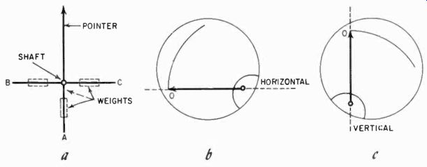
Fig. 108. Tiny weights are used to counterbalance the pointer. The first illustration
(a) shows the general relationship of the weights to the pointer. The pointer
should rest on the zero mark when the meter is in either the horizontal position
(b) or in the vertical position (c).
Balancing is not difficult, but it is a delicate and possibly tedious task. Start with a spotlessly clean bench, and remove the meter from its case. In Fig. 108, we have redrawn the balancing cross also shown in Fig. 102. Weight A counterbalances the weight of the pointer when it is in a horizontal position, and the combination of A, B and C together counterbalance it in any other position. With the meter face vertical and with the 0 mark and the pivot in a horizontal line (see Fig. 108-b), observe the pointer. If it sags off scale, weight A must be moved out from the pivot. If the pointer moves up scale, weight A must be moved in toward the pivot. When this balancing is precise, rotate the meter to the position shown in Fig. 108-c. Now if the meter pointer moves to the left, off scale, either weight B must be moved in toward the pivot or weight C out from the pivot. It does not matter which, since the effect of either is the same in terms of balancing moment at the pivot. However, it is best to keep the distances of the counter weights from the pivot approximately equal.
After this you may have to repeat the first balancing. Be sure in any case to check it. These balance arms are extremely delicate, so be careful how you go about moving the weights. They can be pushed along the arm with the tip of a small screwdriver. Hold the pointer cross in one position by the balancing arm A, not by the pointer!! After balancing, you probably will also have to reset the zero adjustment. This is easily done from the front of the meter, after the movement has been replaced in its case. When replacing the movement, be sure that the zero-adjustment pin slips between the sides of the zero-adjustment bracket. This bracket changes the zero position by changing the fixed attachment point of the top spring a little, thus altering the tension of the spring, which pulls the coil and pointer with it (see Fig. 102).
Selecting a meter
Although many excellent factory made types and kit types are available, you may decide to build your own volt-ohm-meter. The problem of selecting a meter immediately arises. This is not only a technical choice, but also involves the problem of how much you are willing to spend.
There are so many possible choices of meters that only a few general rules can be set down. First of all, do not buy a meter of greater sensitivity than you need. The more sensitive, the smaller the load on the circuit-but one disadvantage is the great resistance which will be needed for higher voltage ranges, since precision resistors of higher values will also be more expensive.
The size of the meter must be considered. If you want accuracy and readability, the largest meter is just good enough. But the instrument will then also be large. If you want a rugged, handy pocket instrument, the meter will have to be small, and you will sacrifice some accuracy in your measurements. If you want reason able accuracy and yet portability, a 3-inch round or 4-inch rectangular meter is about the best choice.
Making your own volt-ohm-meter is a lot of fun, but also a lot of work, and you will not he able to save any money over the kit type instruments offered. But will find in the following sections all the information you will need to build many kinds of VOM's.
A word of caution: Whenever building any equipment including a meter, avoid inserting the meter until the last possible moment, thus avoiding damage to the delicate meter or scratches to its face if it happens to have a plastic front.
Also see: Link | --Guide to VOMs and VTVMs