THE basic meter we have discussed can be used to build many measuring instruments. The choice will depend on what is to be measured, but you will always have to have certain information about the meter you are going to use. You will need to know its full-scale range and its internal resistance. These can be established with very simple tools. Fortunately, the majority of d'Arsonval meters come in standard ranges. Once you have established the approximate full-scale range of the meter, you can with confidence assume it is the next standard range. These standard ranges are: 20, 50, 100, 500 microamps (occasionally you may encounter a 10- or 30-ua instrument, but these are rare); 1, 2, 3, 5, 10, 15, 25, 50 and 100 milliamperes. Anything over 5 ma is unsuitable for VOM's, and even that is high. But the ranges are listed because you may have to recognize unsuitable meters as well. If you buy a new meter, you will certainly know its range and probably also its internal resistance. But if you find a meter in surplus or salvage one from a used piece of equipment, you probably will know neither.
How to measure range
To measure the approximate range of a meter, all you need is a fresh flashlight cell and a handful of resistors. As shown in Fig. 201, connect the resistors in series with the meter, beginning with the highest resistance, until you have obtained nearly full-scale deflection. Start with the highest resistor to prevent overloading the meter and possibly damaging it.
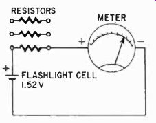
Fig. 201. You can determine the full-scale range of your meter by using the
appropriate series resistors.
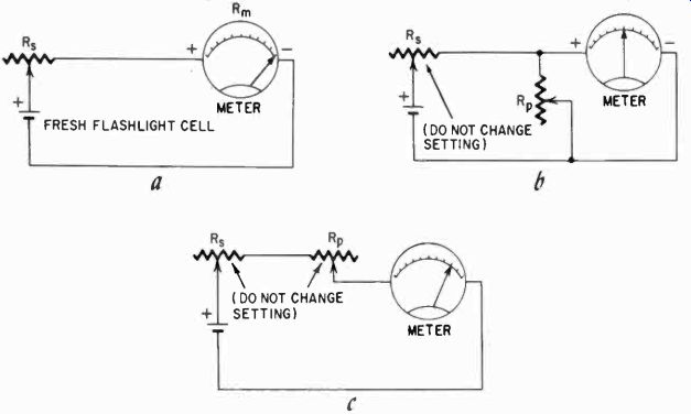
Fig. 202. Steps in finding the internal resistance of a meter. First (as shown
in a) adjust R, for full-scale deflection. Now add R,, (see b) and adjust for
half-scale deflection, but do not touch the setting of R,. Finally (drawing
c), put R, and Rp in series with the meter and then read the deflection.
By referring to table 2-1 you can determine the range of the meter. (For example, if a meter deflects full scale with 3,000 ohms in series, it is a 500-ua unit.) Be sure to observe polarity marks on the meter. These will appear on or near the terminal studs; the positive pole will be marked with a +. On the battery cell, the center small rod is always the-I-.
How to determine internal resistance
To find the internal resistance of the meter, use similarly simple tools. A fresh flashlight cell is the first one. A fresh cell always has a voltage of 1.52. This varies practically not at all and, with the small loads you will be applying, it can be used intermittently for hours without losing much of its voltage.
Next you will need two potentiometers. One (R. in Fig. 202) must be at least the same value as the resistor shown in table 2-1 for that particular meter. Thus, for a 500-ua meter the rheostat or potentiometer should be at least 3,000 ohms. You will probably use a 5,000-ohm pot for this. The other one, which we will call R,,, must be about the resistance you believe the meter to have.
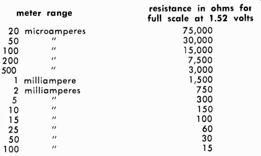
Table 2-1. Series resistors and current ranges for full-scale
Table 2-2 shows some of the common values for popular brands of meters. You can see that for one range the internal resistance does not vary too much. For 500 pa this is 80 to 500 ohms. For R we would then select a potentiometer of 500 ohms.
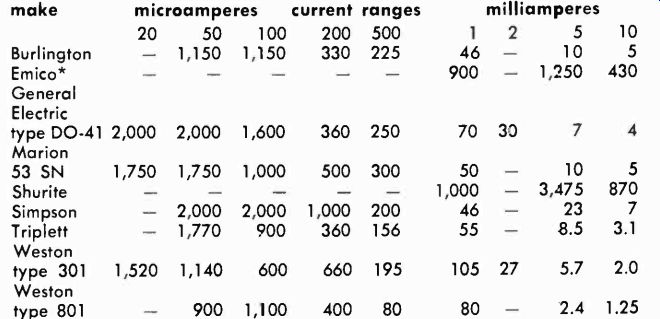
Table 2-2. Approximate internal resistance of representative meters
Table 2-2 shows some of the common values for popular brands of meters. You can see that for one range the internal resistance does not vary too much. For 500 pa this is 80 to 500 ohms. For R we would then select a potentiometer of 500 ohms.
Now proceed as illustrated in Figs. 202-a,-b and-c. First, as in Fig. 202-a, adjust the potentiometer until you get exactly full-scale deflection. Now add R, in parallel with the meter, as shown in Fig. 202-b, and adjust It, for exactly half-scale deflection on the meter, leaving the adjustment of R. strictly alone. Some of the current will be going through the potentiometer and, when the meter shows half the current, the current through the potentiometer will also be half, and thus its resistance will be exactly equal to the meter's internal resistance. But we still have to determine what it is.
This we do next by connecting R. and It, in series with the meter, as shown in Fig. 202-c. The adjustment of the two potentiometers must not be changed when you do this. Divide the battery voltage, 1.52, by the meter full-scale current in amperes. Now read carefully what the meter deflection is. Next, divide the voltage by the current noted on the meter, also in amps. Subtract the second figure from the first, and the difference is twice the meter's internal resistance. Here's an example of how this works:
Suppose you have a 500-ua meter. As in Fig. 202-a, adjust R. for full-scale deflection. You now have in the circuit both R. and the meter resistance, which we will call Rm. The current (.0005 amps) goes through both: 1.52/.0005 = 3,040 ohms, or R. + Rm = 3040.
Next suppose in Fig. 202-c you read the meter at 0.9 of full-scale, or 450 microamperes. R, = Rm, therefore R. 2Rm = 1.52/.0045 = 3,377 ohms. We can expand this to read R. + Rm
Rm = 3,377 ohms.
Since R. + Rm = 3,040 ohms we can substitute this and we then have 3,040 + Rm = 3,377. Transposing, we have Rm = 3,377- 3,040 = 337 ohms.
The accuracy of this measurement depends on two things: how fresh the flashlight cell is, and how accurately you can read the scale of the meter. In Fig. 203, a scale is shown which might be used in a 500-ua meter; the arrow near the 5 shows what your second reading would have looked like. The other arrow is shown to explain how to read the meter as accurately as possible. The scale has five major divisions, each of which represents 100 pa.
Each major division is divided into five equal parts, and thus each of these divisions represents 20 pa. Because the second arrow is shown in the fourth major division, the first digit to read is 3.
The arrow is also two-thirds of the way in the first small division, which is then 2/3 of 20, or about 13.3 pa. Round this figure off and, with the pointer in this position, you would read 313 pa.
There are other ways of determining the internal resistance of meters, but they presuppose the availability of other meters calibrated and ready to use. For example, with an ohmmeter you could simply read the resistance of the shunt, R, after you had adjusted it for half-scale deflection on the meter. On the other hand, the method discussed requires nothing but one standard a fresh flashlight battery-and some careful work in reading the meter.
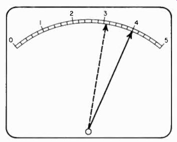
Fig. 203. How accurately you determine the internal resistance of a meter
depends in part on how carefully you read the meter scale. The type shown here
is linear. Each small division has a value of 20 microamperes. Full-scale deflection
is 500 micro amperes.
Making multirange current meters
Most meters in use actually indicate currents other than their original range, by means of shunts and other accessories. If you consider the economics of it, the reason becomes obvious. With a 1-ma meter we can read ranges of 1, 10, 100 ma and 1 amp, or more, simply by using an inexpensive external shunt. The manufacturer therefore needs to make only 1-ma movements for all these ranges, and can do it more economically by far.
To make a meter indicate half the current from the same sup ply or to extend its range to twice the original value, shunt the meter with a resistance exactly equal to its internal resistance.
Similarly, to make a meter usable on a range five times as large, bypass 4/5 of the current through a shunt. The meter takes 1/5, and the ratio between the shunt and meter resistances is the reciprocal of the current ratio, or 1 to 4. In other words, the shunt must be 1/4 the resistance of the meter. For 10 times the original range, the shunt must then he 1/9 the meter's internal resistance.
Changing the meter range
Knowing the internal resistance, you can figure any shunt needed to change the range of the meter. For example, let's consider the 1-ma movement in Table 2-2 that has an internal resistance of 46 ohms. To make a 10-ma unit out of it, we would shunt it with 46/9, or 5.11 ohms.
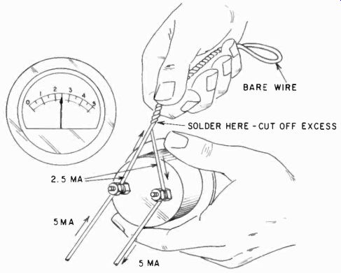
Fig. 204. One method of making a low-resistance shunt. With current passing
through the meter, twist the bare wire forming the shunt until the meter passes
the correct amount of current.
There are several ways to obtain such a resistance. We could buy one for example. Another way would be to make the shunt.
In this case, if you made it from copper wire, use 15 feet, 8-5/8 inches of No. 34 AWG wire, which at room temperature would have very nearly 5.1 ohms resistance. But there is the problem of "at room temperature." If the temperature varied considerably, so would the resistance of the copper wire. For this reason, precision resistors are wound from a wire called Manganin, which is hardly affected by temperature and has about 400 times as much resistance as copper, making it much easier to use. Manganin, or its cousin, Nichrome, which is just about as good, can be obtained from electrical supply houses, but is not otherwise generally avail able. However, for making a few shunts, you will need only a small quantity, and you can obtain some from an appliance repair shop by asking them for burned-out toaster, flatiron and heater elements. They are made from Nichrome or similar wire.
Particularly if you intend to make the meter read very high currents in comparison with its original range, you may have to make your own shunts. To make a 1-ma meter read I ampere full scale, you must bypass 999 ma. In other words, your shunt would have to be 46/999, or .046 ohms approximately. You will not find a ready-made precision resistor to do this job. You'll have to make it yourself.
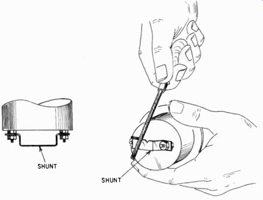
Fig. 205. The shunt must be able to pass its current without an increase in
temperature. A substantial shunt is needed for heavy currents (several amperes
or more). A copper bar makes a good shunt. Keep filing the bar until the meter
reads the correct amount of current. Drill minimum clearance holes for mounting
the shunt on the meter. This will permit maximum copper contact between the
meter and the shunt. Use flat washers on both sides of the clearance hole on
the shunt.
Making low resistance shunts
To make such a low-resistance shunt you can use several methods. One is illustrated in Fig. 204. A copper wire has been attached to each meter terminal, and the wires twisted together, while a current goes through the meter. When the wires have been twisted enough, the meter will show the correct current, and you can solder the twisted ends and cut off any excess wire. If you were to make, say, a 1-amp meter this way, you'd calculate the approximate length of wire needed and make the two pigtails somewhat longer. Then use a current of 1/2 ampere or some such value, and twist the wires together until the meter reads the exact value of the current you are applying.
Notice that in Fig. 204 only one continuous wire is used. This prevents the danger of opening the shunt while the heavy current is on. Opening the shunt under those conditions might well burn out the meter.
Another way to make a heavy shunt accurately is shown in Fig. 205. Here the meter terminals have been paralleled by a heavy wire or bar. With a small file, the cross-section of the bar can be diminished. As it is reduced, the resistance goes up, until the meter reads the correct current value. This method is used only when the shunt is already quite close; it would not be practical to file away half the bar to make the shunt exact.
Notice the essential difference in these two methods. In the first case the shunt has more resistance than needed, in the second case less than the final value. The latter method is sometimes used commercially to calibrate shunts for very accurate indication.
Establishing standards
How would you establish an accurate current of these magnitudes, say 0.5 amp or more? This is really quite simple. Start with a freshly charged auto battery, which is capable of delivering hundreds of amps for short periods if necessary. At 68°F (what we like to call room temperature) and at a specific gravity of 1.280, which is about normal full charge, a three-cell storage battery will have a voltage of 6.363v. This can be a standard. To get a known current, use a wirewound 25-watt resistor of 12 ohms or thereabouts.
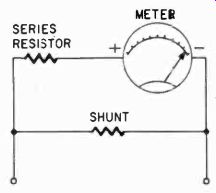
Fig. 206. A small series resistor can be included to modify the internal resistance
of the meter to permit the use of shunts having a convenient resistance value.
If you do not have such a resistor handy, an appliance such as a flatiron or similar heating-element unit can serve as a resistor.
(Be sure it doesn't have an ac thermostat in it.) The manufacturer will have marked the current (at 117 volts) on the device. From this you can, calculate the resistance and then work out the current at 6.363 volts, using Ohm's law. The markings of such appliances may not be accurate, so use several, checking one against the other and averaging the difference. A 1-amp meter, for example, seldom needs great accuracy anyway, unless you are doing scientific experiments. In that case, buy a resistor of known value.
Another way to solve the shunt problem also takes advantage of standard resistors. Suppose you have a meter, which has an internal resistance of 77 ohms. Now suppose also that you make this meter read on a 10 times and a 100 times range. You can obtain resistors of 1 and 11 ohms exactly. Since 99 X 1 = 99 and 9 X 11 = 99, we could use these shunts nicely if our meter had an internal resistance of 99 ohms. But it has only 77. So to make matters right we add a 22-ohm resistor in series with the meter, "inside" the shunt. This now causes the exact amount of the current we want to go through the meter, 1/9 or 1/99. It does not matter how we achieve this; the meter will read accurately. This scheme is illustrated in Fig. 206. Thus, if we had to change meters in midstream, we would simply change the little series resistor to fit in the new meter, provided of course it has an internal resistance of less than 99 ohms.
Changing shunts
It is not convenient to change shunts for a multirange setup all the time, so arrange the meter and shunts with a switch, as shown in Fig. 207.
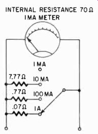
Fig. 207. Switched multirange current meter. Re member to include switch contacts
and leads to the resistors as part of the shunt. The meter should he disconnected
while switching current ranges, unless the switch is of the shorting type.
Here then is a multirange ammeter or milliammeter, as the case may be, and you now have all the information you need to make either from your basic meter, whatever its range and internal resistance.
Making voltmeters and multirange voltmeters Let us analyze the necessity of using series resistors with meters to make them read voltage. Suppose we try the 1-ma meter we used before. It had an internal resistance of 46 ohms. If we connect this to a 1.52 volt battery, and ignore the internal resistance of the battery, the current would be 1.52/46 .033 amp, or 33 milliamps, 33 times as much as the meter can take. That is why we would put in a series resistor, and you can quickly see what value it would have to be. To reduce this current to 1 ma for 1.52 volts, we need a total of 1,520 ohms. The external resistance should then be 1,520- 46, or 1,474 ohms.
We cannot ignore the meter's internal resistance in this case, for the resistance is more than 3% of the total. If we did, our meter would be 3% off. But if we made a scale for 15 volts and ignored the meter resistance, the error would be only 0.3%, and on a 150-volt scale this is really very little. Therefore, when building a voltmeter from a basic meter, the series resistors for the lower ranges must be made with greater accuracy than the others.
In this case, for example, with the 1-ma meter, we would use resistors of 1,474, 15,000 and 150,000 ohms, respectively, for those three scales. These can be easily arranged with a switch, as shown in Fig. 208.
The simple way to calculate the value of these resistors is to multiply the voltage range by 1,000 and divide by the meter full scale range. Thus, if the meter is a 500-microamp unit which we want to provide with a 30-volt range, divide 30,000 by 0.5 (ma) and you come up with a series resistance of 60,000 ohms. It becomes obvious that a meter resistance of 200 ohms is not going to make very much difference: actually not even enough to detect on the scale! Making series resistors Series resistors are much easier to make than shunts. Almost any value can be made by adding resistors in series, or by paralleling one or more resistors. Use the standard flashlight cell as a basic calibration source or you can, of course, use a number of them. Thus, for a 1.5-volt scale you would use only one, but a 15-volt scale would use four, which would be a fraction over 6 volts. This would get almost half scale on a 15-volt scale and would provide a good calibration point. For a 100-volt scale, at least 20 of them are required to get up to only 30 volts, and this would be cumbersome and, eventually, expensive. But because series resistors are what they are, you could calibrate for a 15-volt scale, again calibrate for a 15-volt scale, and add the two resistors together. In this way you can calibrate series resistors for a 30-volt scale-or any multiple of 15 volts-with care, with only four flash light cells.
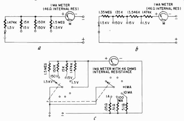
Fig. 208. Switching arrangement (drawing a) for series resistors to obtain
a multi-range voltmeter. An alternate arrangement (b) is used in some commercial
meters for reasons of economy, but has no particular advantage for the home-built
instrument. The combination multimeter (c) uses shunt resistors when on the
current range and series multiplier resistors for measuring voltage. The range
switch in this example is made up of two wafer sections of a rotary switch,
mounted on a common shaft.
Switching arrangements
There are two basic ways of connecting a multirange meter with its switch and resistors. One is shown in Fig. 208-a and the other in Fig. 208-b. The difference is that in the first case the resistors can be standard values, while in the second they always are odd values because the lower-range resistors are subtracted from the total for the higher ranges. However, if you are in the process of matching resistors anyway, one method is as good as another.
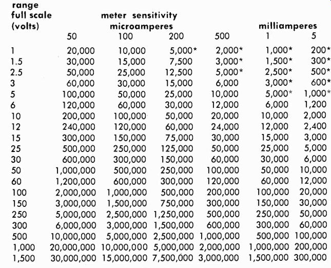
Table 2-3. Values of "multiplier" series resistors for commonly
used scales and various meter ranges *Meter internal resistance should be subtracted.
Table 2-3 shows common values of series resistors for meters of different ranges. Note in the column for the lowest range that the meter internal resistance must be subtracted, whatever it may be. This table is arranged for the switching scheme used in Fig. 208-a.
It is entirely possible to join a multirange current-switching system with a multirange voltage-switching system for one meter, ending up with the familiar multimeter, with the exception of the resistance-measuring ranges, which will be discussed in the next section. Fig. 208-e shows a combination multimeter. Usually we would also have other functions, which we must yet discuss.
Instead of switches, simple pin jacks could have been employed, requiring the user to insert the test lead in different jacks for different ranges. This is done, even commercially, but is not so economical that it merits much consideration, except for making the instrument extremely compact.
Making ac voltmeters
From our early discussion of the d'Arsonval meter, you may remember that this meter depends on the magnetic field created around the coil. Should we apply an alternating current to the coil, the magnetic field would reverse itself as many times as the current. The coil and pointer have considerable inertia, and they could not possibly follow such alternations. Consequently this meter refuses to indicate anything when we try to measure ac with it. To do so, we must first turn the ac into dc.
Meter rectifiers
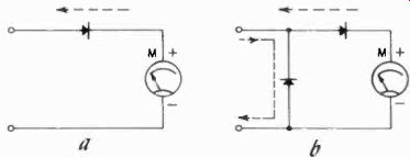
Fig. 209. The illustration at the left shows the meter used with a half-wave
rectifier. The arrangement at the right has an advantage in that it reduces
the amount of reverse current through the meter.
This is done, as everywhere else, with rectifiers. They need only be very small rectifiers, since we will be dealing with very small meter currents. Some essential facts about rectifiers must be considered in relation to meters. One is that rectifiers are not perfect. Metallic rectifiers always have some reverse current, even if this is very small in a good rectifier. Thus. if we used the scheme shown in Fig. 209-a, we would deflect the meter with each positive pulse of current, and we would subtract a little from that with each negative pulse. This could be made more efficient by using the scheme shown in Fig. 209-b, where the other rectifier presents a low-resistance path for the ac when the negative half-cycle arrives. This would prevent most of the reverse current.
When we pass such a rectified ac through a meter, the meter will stay in one place as long as the current is on, because the meter has a lot of inertia in its mechanically moving system of coil and pointer. But actually the current through the coil wanes and waxes regularly, and even is zero for as long a time as it is on altogether. Thus, with a half-wave rectifier, the energy required to keep the meter deflected (remember that time x current = of series resistors. Here we have indicated the series resistors for dc for the particular meter drawn, but we cannot sensibly indicate the series resistors for the ac ranges because we cannot calculate them. They depend too much on the characteristics of the rectifier.
Using separate series resistors has the advantage that we need not draw as many scales on the meter face. This means that, in general, we can read the scales more accurately because as scales get closer to the pivot point, they become shorter. To some extent, this makes up for the inaccuracy of nonlinearity at the lower end of the scales. Of course, it costs more to put in extra resistors and switch points.
Since we cannot calculate the ac series resistors, we must either depend on the recommendations of the rectifier manufacturer, if given, or we must establish the values empirically by cutting and trying. For this you will need accurately known ac voltages. (We will discuss this more fully under calibration.) Ac vs dc scales On practically all VOM's, the ac scales are printed in red, so that they can be clearly distinguished from the dc scales. Sometimes, even though separate scales are used, the manufacturer uses the same numbers to avoid too much crowding of the face. This can be done by shifting the ac scales somewhat by an extra shunt across the meter switched in when the ac is used, so that the figures come closer together on the two scales. An example of scales using the same numbers is shown in Fig. 212.
Vom's seldom have one or more alternating-current ranges. The reason is that to use the d'Arsonval meter we must rectify the ac, but to measure it as current we must put it in series with the meter and so we would no longer be supplying ac to the load.
One manufacturer gets around his dilemma by making ac current ranges from ac voltage ranges by measuring the ac voltage developed across the special current resistors built into the instrument. Although the scale will read ac current the instrument is actually measuring ac voltage developed because of the current.
Most instruments do not have ac current ranges, in part because they are needed less than the others.
Calibration of ac voltmeters
The calibration of ac voltmeters is usually done at 60 cycles.
This is not the highest frequency which can be measured with the instrument, but there is a limit, set by the characteristics of the rectifier and the impedances in the circuit, as well as the capacitances. There are no real capacitors to deal with, but only a stray capacitance-the effect of a number of components close together with insulation in between. Some high-quality instruments are usable to 500 khz with good accuracy, and this is about as much as you'd expect from them anyway.
To calibrate ac voltmeters then, you will need known ac voltages, and this is not as easy as it was with dc, where we had batteries to rely on.
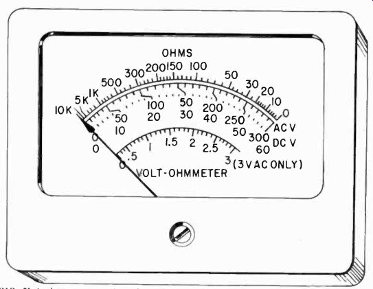
Fig. 212. Volt-ohmmeter scale using the same digits for the ac and dc scales.
Note the compression of the ac scale at the low end, and the separate ac scale
for low voltage.
Your utility company may not always be able to give you the exact voltage. The voltage on both sides of distribution transformers will vary with load. Voltages inside the house or building will also fluctuate.
Ac calibration methods
One practically standard source of voltage is the 117-volt power line. Your utility company can sometimes tell you what the voltage is in your area. Then to obtain other voltages you could use voltage dividers made from accurate resistors. This has one complication: when you shunt the low resistor in the divider with the meter, series resistor and rectifier, you will in effect lower the voltage; and since you are in the process of determining the ac series resistors, you cannot allow for this drop exactly. Only if you use a very sensitive instrument, in which the series resistor on the low scales is still very high in comparison with your lower voltage-divider resistor, can you ignore this inaccuracy. (This is analogous to the dc situation in which the meter resistance could not be ignored on the lower scales, unless you had a very sensitive meter.)
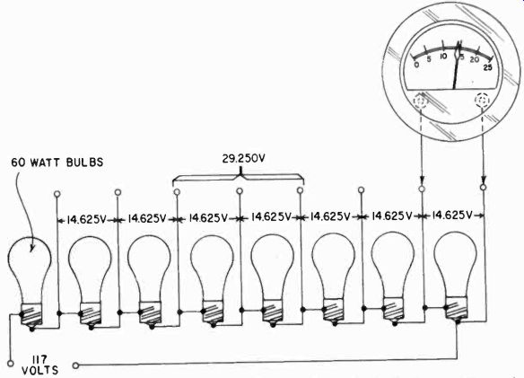
Fig. 213. The line voltage, plus a number of electric-light bulbs, can be
used for calibrating the ac scale of a VOM.
Fortunately there is a fairly simple solution to this problem, again using very simple tools. Ordinary light bulbs are machine made and, when you get bulbs from the same manufactured batch, they are surprisingly close in tolerance. They vary less than a percent or so in resistance value. If you take a number of, say, 60-watt bulbs and put them in series across the line, they will glow barely if at all, but you can be quite confident that each will have the same voltage across it, all the same fraction of the line voltage.
In Fig. 213, each bulb has 14.625 volts across it. This can be used to calibrate scales from 15 to about 30 volts, tapping off higher points in the chain for higher voltage scales. But be sure your light bulbs are all the same, and all from the same box.
This method of calibration need not take the meter parallel resistance into account because the light-bulb resistance is so much less that the meter circuit has no significant effect. The cold resistance of a 60-watt bulb is about 15 ohms. Even a 1-ma meter would need, on its 1.5-volt scale, 1,500 ohms resistance, and on its 15-volt scale 15,000 ohms. Obviously this is not going to affect the voltage across the 15-ohm light bulb materially.
Better calibration can, of course, be obtained through comparison with a precision-calibrated instrument. But the method de scribed here can be readily used by those who wish to build an ac voltmeter and do not have expensive calibration instruments for comparison purposes.
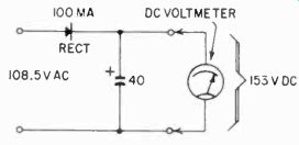
Fig. 214. Method for determining the amount of line voltage if the scale of
your meter has not been calibrated. Read the peak voltage as dc (by using a
rectifier and filter) and then divide this amount by 1.41.
Another way would be to take a multi-tap transformer to some one who has an accurate instrument, measure the transformer voltages exactly and use these as standard voltages. Then you have to make sure that the 117-volt primary voltage was exactly the same in both cases. Each method has its own errors.
The final accuracy of your instrument will depend on how carefully you work, how well you select your "standards" and how good your meter is. In calibrating with light bulbs, for example, a careful calibration job would call for exchanging the bulbs after the first calibration and doing the job again; and so on, at least five or six times, averaging out any error that might be present because of differences in the bulbs. If five or six calibrations with bulbs from different positions in the chain give the same result, you can be fairly sure that your accuracy is very good, within the limits of your knowledge about the line voltage.
If you cannot get accurate information about the local line voltage from the utility company, there is a simple way you can measure it, provided you have first calibrated the dc portion of your instrument. If you take a good selenium rectifier and a large electrolytic capacitor and put them across the line, the dc to which the capacitor is charged, in the absence of a heavy load, is what is known as the peak value of the ac voltage, which is 1.41 times the effective voltage. Thus, if you measure with the dc meter range a voltage of 153 across the capacitor (the meter is not a serious load), the ac line voltage is 153/1.41 = 108.5. The capacitor (see Fig. 214) must be very large, at least 40 pf, and the rectifier at least 100 ma to allow you to ignore the meter load and the leakage of the capacitor.
Making a supersensitive meter
Not so long ago, the 20,000 ohms-per-volt VOM was used for most shop work, with a vtvm for high-impedance measurements.
Today multimeters with sensitivity ratings of 100,000 ohms per volt are standard equipment in many shops. They do not need external power, like the vtvm, and are usually more compact and easier to carry. They have no tubes to age and affect calibration, and need no warmup period. The input resistance is equal to that of a 10-megohm vtvm on the 100-volt range and exceeds it on higher ranges.
A 100,000-ohms-per-volt dc voltmeter can be made around a 10 pa dc meter, one multiplier resistor for each range, and a selector switch. The diagram in Fig. 215 shows such an instrument.
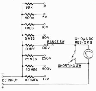
Fig. 215. A 10 microampere meter can be used as the basis for constructing
an instrument having a sensitivity of 100.000 ohms per volt.
To find the correct multiplier resistance for each range, multi ply the ohms-per-volt sensitivity by the full-scale voltage for the range. If the multiplier resistance is less than 100 times the internal resistance of the meter, subtract the meter resistance from the calculated value of the multiplier for greater accuracy.
Construction precautions
In constructing this or a similar meter, observe these precautions:
1. Insulate the terminals from the panel with high-grade poly styrene or ceramic material.
2. Use a high-grade ceramic-wafer range selector switch and do not touch the ceramic any more than absolutely necessary. After wiring, clean the ceramic with carbon tet or lacquer solvent.
3. If the meter is to be used on a metal panel, be sure to so specify when ordering it.
4. Use special instrument type resistors for values above 50 meg ohms. Do not touch the bodies of the resistors. After soldering, clean them with a solvent recommended by the resistor manufacturer.
5. Make the case as nearly airtight as possible to keep out dirt and moisture.
6. Keep the shorting switch closed when the meter is not in use, to protect the delicate movement from shocks.
7. Observe the following for extreme precision or laboratory-type accuracy in the instrument you are planning to build:
a. Select a meter with a mirrored scale. Always read the meter from directly in front of the instrument so the reflected image of the pointer and the pointer itself are lined up. Thus, when the eye is in the proper viewing position, the reflected image is not visible. This eliminates errors caused by parallax.
b. Multiplier and shunt resistors should have a tolerance of at least 1% and greater accuracy is recommended.
c. If wirewound resistors are used for ac ranges, be sure they are a non-inductive type. Otherwise, they will be reactive and can cause errors.
8. Whenever possible, leave the meter installation until the last step in the construction. Chassis are handled roughly during construction and the meter may be damaged by jotting or its face broken or scratched.
9. Never store instruments with plastic-faced meters in cabinets with acetone, paint removers and other service and industrial chemicals. Fumes from many of these compounds will attack the meter face, eroding it so it crazes and becomes opaque.
10. Never wipe the meter face with a dry cloth while the instrument is in use. Friction may develop an electrostatic charge capable of producing large errors in the readings. When a meter cannot be zeroed or its needle tends to stick, the trouble may be caused by a heavy electrostatic charge on its face. If a charge develops on the meter face, discharge it by breathing heavily on the glass or by treating it with an antistatic compound used for cleaning phonograph records.
The very first command about using meters is that they are delicate instruments and must be treated as such. This cannot be emphasized too much, particularly if your livelihood depends on the availability of your meter. An instrument, once dropped, even though it may appear to be functioning well enough, should be regarded with some suspicion, and the various calibrations should be checked with appropriate sources as soon as possible. For example, if you have a meter with a permanent shunt, a strong shock may disconnect it and, although the meter seems to function well, it will indicate high on all its ranges, without any obvious indication something is wrong until you check it against a standard source, such as a fresh flashlight battery.
An alternative method to building an ultra-sensitive VOM (such as the one described here) is to use a less sensitive VOM in conjunction with an external amplifier. Read the section entitled "amplification for the VOM" beginning on page 154 in Section 8. See also the description of the pin-jack VOM beginning on page 63 in the next section. In this instrument, a basic 40-ua movement, with the help of a transistor amplifier, can be used to measure currents as small as 1 pa.
Also see: Link | --Guide to VOMs and VTVMs