In Section 2 we discussed multirange current and voltmeters in general. A good deal remains to be said about these before the matter of construction has been taken care of, but first we must consider resistance measurements, the last function of the VOM.
There are three basic ohmmeter circuits, each with its peculiar advantages and disadvantages. The first (Fig. 301) is called the series circuit. The deflection of the meter depends upon the resistance in the circuit. If we short the terminals and adjust the potentiometer for full-scale deflection of the meter, and then insert an unknown resistance across the terminals, the meter will deflect less. The reduction in deflection will be proportional to the inserted resistance.
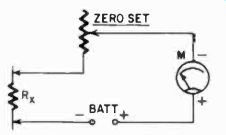
Fig. 301. This is the basic circuit for a series type ohmmeter.
One real advantage of this circuit is its simplicity. Its disadvantage is that the scale of such a meter will be crowded on both the low and high ends.
But this is not its only disadvantage. Consider what happens when we adjust for zero with a fresh battery. If we use a 1-ma meter, then we know we must have about 1,500 ohms in the circuit for full-scale deflection. The battery in the circuit is 1.5 volts. At full scale the meter will draw 1 ma. The required resistance is:
E 1.5 R T
= .001
= 1,500 ohms
An unknown resistance of about 1,500 ohms would then give us half-scale deflection. When the battery has aged and provides only 1.2-volts, we again adjust for full deflection, which now requires only 1,200 ohms in the circuit. Next, if we again test a 1,500-ohm resistor, we will get a good deal less than half-scale deflection.
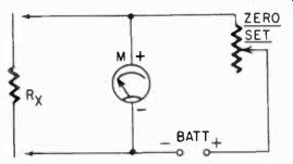
Fig. 302. Fundamental circuit arrangement for a shunt type ohmmeter.
Consequently, the series ohmmeter can be calibrated only for one particular battery voltage. In part, but not entirely, the drop in voltage is made up by an increase in internal resistance of the battery. The series ohmmeter is not very useful as a battery-
powered instrument. If we provide it with a dependable ac power supply with rectifier, it can be used, if you wish to put up with the crowded scale. In general, the series ohmmeter is not used commercially.
The next logical circuit configuration would be a shunt ohm meter circuit, shown in Fig. 302. It uses the principle that was discussed in making shunts for current meters. When the meter is adjusted for full-scale deflection, any resistance we put in parallel with the meter will decrease the deflection. Note the difference between This reading and that of the series meter. In the series meter the less the resistance, the less the drop in meter reading. Here the smaller the resistance, the greater the drop in the meter reading.
For the series meter, the zero point is at the right, while the shunt meter has its zero point at the left.
The shunt ohmmeter is a useful instrument for measuring very low resistances only. Fig. 303 shows the difference in the two scales, the top scale for the shunt circuit, the bottom scale for the series type circuit. The shunt type ohmmeter is not found in commercial or kit type meters, but is sometimes made by hobbyists and experimenters to measure low-value resistors.
The shunt meter has one serious disadvantage. When not in use, the meter circuit will remain across the battery and will cause it to discharge.
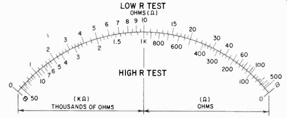
Fig. 303. This illustration shows the difference between shunt and series
ohm meter scales. The upper scale is for the shunt type; the lower for the
series. The shunt ohmmeter is suitable only for measuring low resistances.
Both scales have crowded areas. Note that the location of the zero point is
different for each scale.
Next we have the potentiometer type of ohmmeter, and this circuit is used by virtually all manufacturers of commercial VOM's.
See Fig. 304. The meter and the zero-set potentiometer are connected across a standard resistor. When the terminals are shorted
for zero setting the meter, the meter circuit reads the battery voltage and again is adjusted for full-scale deflection. When we insert an unknown resistance between the terminals, the meter will deflect less, since the voltage created across the standard resistance will be less. In fact, it will be a proportion (of the battery voltage) which depends on the unknown resistor, and we can calibrate the scale in ohms for this unknown.
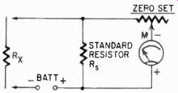
Fig. 304. Basic schematic of a potentiometer type ohmmeter.
Now it is obvious that when we change standard resistors, say to one 10 times higher, that the scale will also read 10 times the resistance--with some reservations. One of these is that the meter circuit must have a high resistance in comparison with the standard, or the shunting effect of the meter will change the range. It is not always possible to make the meter such a high-resistance circuit, and the standard resistors will not always be an exact multiple of the lower ones. We must also consider that the battery is not without internal resistance. Therefore, when we short the terminals, we do not have the exact voltage that is across the standard resistor but we have slightly less. However, when these are compensated for, we can have an almost exact overlapping of scales; in commercial VOM's the same scale is generally used for all ranges. A few instruments use the shunt type meter for the lowest range, and in that case they have a separate scale for it.
But this is not the only problem. Another concerns battery voltage. Consider the simplified diagram of the VOM resistance-measuring circuit shown in Fig. 305. Here the lowest range has 11.5 ohms for a standard resistor, and the next range (100 times as large) has 1,138 ohms plus 11.5 or 1,149.5 ohms. Now if we were to continue in this way, the next "standard" would be about 115,000 ohms. To get half-scale deflection we would need about 25 microamps, since the instrument has a 50-ua meter. But, unfortunately, if we insert 115,000 ohms in series with a 1.5-volt battery, we would not get enough current for half-scale deflection; we would get only about 14 pa. To remedy this, the highest range uses a different battery a 6-volt one. But we do not want to use the 6 volts across our standard resistor, for this would mean we would have to change range on the voltmeter circuit.
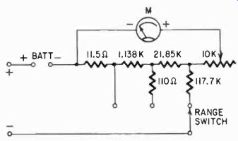
Fig. 305. Simplified schematic of a potentiometer type ohmmeter circuit used
in a commercial kit. The battery, multiplier and standard resistors are switched
simultaneously. The battery switch is not shown.
The solution is to put the multiplier, not in the meter circuit, but in the battery circuit instead, which gives us the configuration of resistors and switching shown here. Not shown in the basic diagram is the fact that we also switch batteries. However, the point of importance here is that the meter can obtain the necessary 25 pa for half-scale deflection since we now have 6 volts across about 225,000 ohms, and this is more than ample.
The potentiometer circuit configuration is common in VOM's.
Usually the lower ranges are made with standard resistors which are multiples, except for the necessary compensation for meter and battery internal resistances, but the higher ranges deviate from this pattern in the manner shown in Fig. 305.
There are other ways to measure resistance; in fact, there are much more accurate ways than with ohmmeters, which give only close approximations. One simple method is the measurement of current from an exactly known voltage source, in the manner of the series ohmmeter, but without bothering with any zero-set system. Then each time the resistance must be calculated from the current reading. But this, although perhaps accurate, is cumber some, hence the demand for ohmmeters. However the system can be used with the meter current ranges when unusually high resistance must be measured.
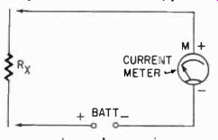
Fig. 306. Method of calibrating un known resistors using a fresh battery and
an accurate current meter.
The meter can also be used as the null detector in a bridge circuit for the measurement of resistance. Commonly, ohmmeters of the potentiometer type are sufficiently accurate for service and experimental work. Most manufacturers decline to give an accuracy guarantee of less than 5% on the resistance measurement. particularly since only half of the scale is legible enough for such ac curacy. When using an ohmmeter of the potentiometer type, it is customary to select the range in such a way that the resistance to be measured falls in the right-hand 60% of the scale, where the divisions are the largest and the reading is the easiest and most accurate.
Calibration of ohmmeters can be done in two ways. An ohm meter can be compared with another, using potentiometers to get different readings. If another ohmmeter is not available for comparison, a number of standard resistors can be used for checkpoints on the scale, and the more points that are marked, the more ac curate the ohmmeter will be. But, again, if standard resistors are not available, you can go to work with the same simple tools used for constructing shunts and series resistors. The series current method can be used to determine with good accuracy the values of "standards" to calibrate the potentiometer type circuit. Again you must make sure you have a fresh battery, for this is now your standard. (See Fig. 306.) Conversely, if you cannot be sure of your voltage, but have one accurately known resistor, you can use this to measure your voltage--if you know the meter's internal resistance (which you can measure, as shown in Section 2) and if your known resistance is high enough so you can ignore battery internal resistance. Battery internal resistance for dry cells usually runs between a few ohms when they are new to about 14 to 20 ohms when they are thoroughly aged. It also varies with different manufacturers, and we cannot set one certain figure as the internal resistance of a battery. It can be measured, however, if you know the exact internal resistance of a meter, (it must be a sensitive type), the exact voltage of a battery in open circuit and the exact resistance of a precision resistor. Then, when you put these in series, the meter should read current which you can compute with Ohm's law. In actuality it will not; there will be some slight discrepancy, due to the battery's internal resistance. It usually is not a serious factor.
One difficulty in making your own ohmmeter is the necessity of calibrating a scale right on the meter. This requires that you have the meter open for the calibration procedure. This can be circum vented by making an accurate calibration table, keeping an ac curate record of the current readings on the meter and drawing the scale from this all at once. Another alternative is not to provide a separate ohms scale on the meter at all, but to keep the calibration in the form of a curve, which shows current readings for many values of resistance on all the ranges available.
Fig. 307-a shows a typical home-made VOM with a 55-ohm internal resistance meter, and Fig. 307-b shows the resistance calibration curves for the instrument. The ohmmeter circuit here is a shunt type meter on the low range and a series type meter on the high range. During calibration, and also of course during repeated use, the zero setting must be frequently checked, for the accuracy of the whole measurement will depend very much on this accurate zero setting. This is the "repeatability" aspect of measurement.
Building your own instrument
The decision as to what type or class of instrument you want to build is something only you can decide, but we can give some broad general considerations of what might be needed for certain kinds of work.
Resistors: R1-2,000 ohm wire-wound variable; R2-3,000 ohms, 1/2 watt; R3-10 ma shunt, 6.11 ohms; R4-100 ma shunt, 0.555 ohm; R5-1,000 ma shunt, 0.055 ohm; R6-1,000 volt multiplier, 0.9 megohm, 1/2 watt; R7-100 volt multiplier, 90.000 ohms, 1/2 watt; R8-10 volt multiplier, 10,000 ohms, 1/2 watt. (All resistors should have a minimum tolerance of 5%.) Meter: 0-1 milliammeter.
Battery: 4.5 volts.
Switch: 9-point, 2-pole selector.
Fig. 307. Simple VOM (a) designed around a meter having an internal resistance of 55 ohms. The lower illustration (b) shows calibration curves for the ohms ranges of the instrument. These curves can be kept separately or used as the basis for calibrating a special scale on the meter.
A meter such as that shown in Fig. 307 would generally be in sufficient for service and repair work, but it would do nicely for the experimenter who does not plan to build high-performance receivers or sensitive instruments of other types. The 1-ma instrument would, however, be too much of a load on such circuits as detector, discriminator or avc circuits and could not very well be used for alignment in these cases. For this, a meter with at least 20,000 ohms per volt is needed; in other words a 50-ua meter should be used. If you have a more sensitive instrument, such as a 10-ua meter, it can be used just about anywhere where normally a vacuum-tube voltmeter would be called for. (Most manufacturers list operating voltages as measured with a vtvm, not a VOM.) Cost is another important consideration. Obviously the expense of the basic meter is the biggest item. Incidentally, it will be difficult for you actually to beat the price of kit type meters, unless you have a lot of usable parts or even a usable meter on hand. It is possible for kit manufacturers to offer their kits at such economical prices because they buy their parts in fantastic quantities.
If you have to start from scratch with parts, it might be advisable for you to read section 4, describing kit type instruments, before launching on your own construction plans. Only if you have some justification for building your own, such as having parts available or requiring ranges not generally offered, or just because you'd like the fun of building your own (although it may cost as much as a kit) should you proceed. A packaged kit will not only save you money, but unless you have the skill and the equipment, your home-built VOM will not have the professional appearance of the kit.
But once you do decide to build, the first matter to decide is the ranges required; the choice of a basic meter is based on this. Or working the other way around, with an available meter, determine what are the most extreme ranges possible. From there you can go on to calculating the necessary series and shunt resistors, the switching required, the box to house the affair in, the terminals, and last but not least, the method of marking the front panel, and how to make meter scales for your basic meter.
If you have or intend to get only a 1-ma meter, the instrument in Fig. 307 is about the best you can do as far as ranges are concerned. The application of such an instrument will seldom call for other ranges. For a more sensitive meter you can construct a circuit such as that shown schematically in Fig. 308. This instrument uses a 50-ua meter with 1,000 ohms internal resistance. The design circumvents the most complicated switching problems, and uses a switch only as a function selector. Ranges are selected by a number of pin jacks, one for each range. The function switch selects the ac and dc voltage ranges, the current ranges and the resistance measurement.
There were three important reasons for building the instrument as shown. First, the meter was available, salvaged from a pH-measuring instrument at very little cost. The pin jacks obviated the need for a relatively expensive multi-point switch and also saved a great deal of space. And the low-voltage range was desired for the reading of thermocouple voltages. The low-resistance scale was included mainly because other ohmmeters in the shop adequately cover all but such a low scale.
Several features in this circuit are of interest. The current ranges are provided with what is known as an Ayrton shunt circuit, so designed that the meter always has a ring of resistors in parallel with it, providing some protection against overloading of the meter. The Ayrton type shunt is computed with the following formula:
R., ± R, Rt = n in which Rt is the resistance between taps, R. the meter's internal resistance, Re the total shunt resistance and n the range multi plier. The lowest range, 50 pa, of course. does not get any shunt, and this range is used with the switch in the "voltage" position.
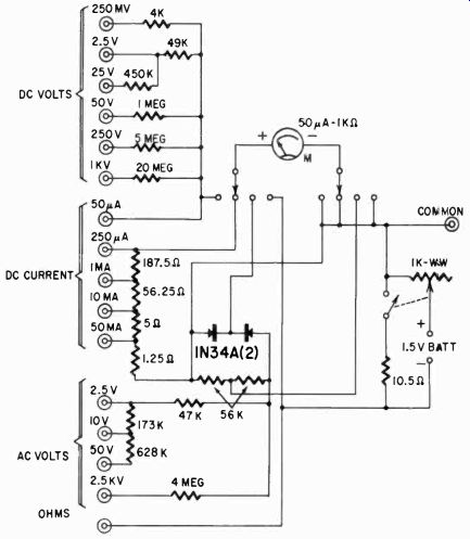
Fig. 308. Schematic for a vom built around a meter having a full-scale deflection
of 50 microamperes and an internal resistance of 1,000 ohms.
The lowest of the higher current ranges is 250 pa, and this deter mines the total shunt around the meter. You need no formula to determine that this must be 250 ohms for a 1,000-ohm internal resistance meter. The next total shunt resistance between pin jack and common is then
1,000 + 250 / 20 = 62.5; next 6.25 and 1.25.
The resistances are made up cumulatively, calling for 1.25, 5, 56.25 and 187.5 ohms, between pin jacks, as shown in the diagram.
The resistance section is a simple shunt type meter, with the meter shunted down for 10 ohms midscale. This requires an 11.1-ohm shunt, but the additional resistance in the leads and switch contacts necessitated the use of a resistor labeled 10.5 ohms (what ever its exact value was). No other ranges were desired, and the switch to disconnect the shunt was mounted on the potentiometer.
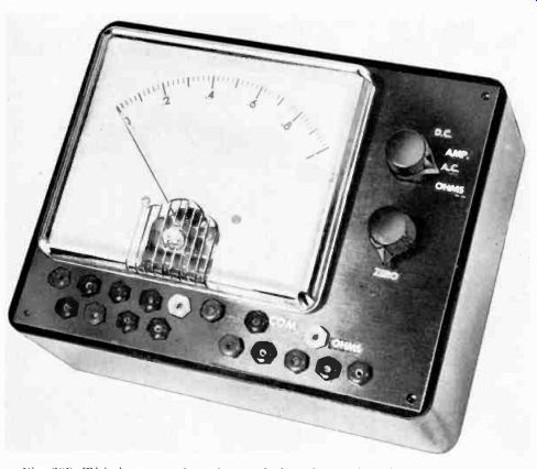
Fig. 309. This home-made unit was designed for a 50-microampere meter.
With a separate switch, another range 100 times as large (1,000 ohms midscale) would have been automatically obtained with the switch off. The switch is necessary to avoid discharging the battery when the instrument is not in use.
Rectifiers used for the ac voltages were 1N34A's, also because they happened to be on hand. The range resistors were determined empirically. With other 1N34A's other resistors might be needed since the diodes are not all alike. However, the use of 1N34A's has one advantage over copper oxide rectifiers: there is very little compression of the scale, and only at the very lowest end. So little in fact that, when the meter resistors for the ac range were selected, they were chosen so that full-scale ac and dc would use the same scale. This holds down to about 10% of the scale, where it should not be read in any case.
Fig. 309 shows the completed instrument. Scales were obtained photographically from another VOM by a method which will be described shortly. The meter chosen had the same progression of 2.5, 5 and 10. No ohms scale was made; a separate ohms calibration curve is pasted on the side of the meter.
Fig. 310. The mounting board, held in place by the meter studs, is a good
support for the resistors and rectifiers in the instrument. The mounting lugs
on the board should be properly spaced to accommodate components without excessive
crowding. Make sure that clearance holes in the board for the studs are large
enough so that no strain or twisting force is placed on the meter.
There are many ways to make your own VOM, starting with a great variety of basic meters and almost any ranges you desire, provided the basic meter is capable of them. Construction can be kept simple, as the instrument illustrated, or it can be made complex, as in commercial instruments using a single switch to select all functions.
Do not mount the meter in the box until the last possible moment, to avoid damage to the meter. Plastic boxes of the proper size are available, and with these and the white decals available for marking terminals, switches and potentiometer, a professional look can be given to the instrument with careful work. Resistors need not necessarily he high-precision units if you have some way of selecting resistors from a large supply. Accuracy of resistors can be obtained by using several in series and parallel. Or you can approximate with the nearest standard resistance value. For example, a 56-ohm resistor is a standard item, and the 56.25-ohm resistor required in the homemade instrument shown is less than 1/2% larger. This sort of discrepancy would be less than a line thickness on the scale of the meter.
Physical construction of the meter can also be varied a lot. It is advisable to use a box which is large enough to hold all components comfortably; crowding parts is an invitation to short circuits or poor workmanship. Never apply heat to meter terminals; many of them have soldered connections on the inside of the studs. Make the meter connections to lugs of the proper size, and after soldering these, place them on the meter studs. Never apply heat in any serious amount to diodes used for meter rectifiers. Mount all parts securely. You can often use the switch contacts or pin jacks for mounting multiplier resistors. If not, a good method of construction is to attach a mounting board to the meter studs, and use the mounting board for holding the resistors and rectifiers. (See Fig. 310.)
Making meter scales
One of the most sensible approaches to building your own instrument is to make the ranges fit available scales. Making or changing scales on a meter is one of the most tedious and difficult jobs in building the instrument. By looking at a scale, you can determine whether it is a series, shunt or potentiometer type ohms scale, remembering that the series scale is crowded on both ends, the shunt scale has the zero point on the left and the potentiometer scale is crowded only on the left end (and has the zero on the right, like the series scale). Thus, if you find a meter which already has an ohms scale, make the ohm ranges fit the scale, rather than vice versa. This is not as difficult as it sounds; in a potentiometer, series and shunt scale, half-scale indicates the resistance in the meter circuit.
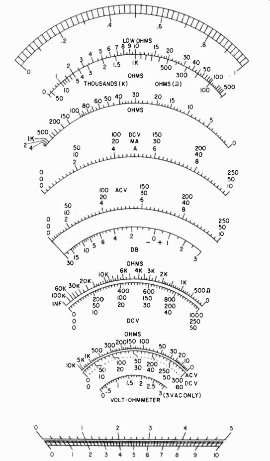
Fig. 311. Various types of VOM scales used in commercial instruments.
If you must make new scales there are a number of ways of going about it, but only a few good ways. If you have a scale which must be specially calibrated, make a calibration curve and then from this draw a scale which is several times as large as the final product. A large scale is easier to draw and, when you reduce it photographically, any errors are likewise reduced, and so are any irregularities in the lettering. This is a very good way to produce any scale if you will remember that the instrument pointer covers an arc of 90°. Naturally, the scale is a part of a circle.
Another good way, using photography, is to start with scales on another meter, or in a book such as this. Fig. 311 is a reproduction of a number of commercial VOM scales. Photograph the page and print each scale to the size which you need. Then combine them by cutting them out, after printing, pasting them up together and then re-photographing, after which they can be printed together in the proper size for the meter. For film you could use a contrast Ortho film or a commercial film, with D-11 developer, or Kodalith Ortho film. The Kodalith is available in only 5 x 7 and larger, and for a smaller camera would have to be cut.
If you have a roll-film camera, but can focus at close range with a closeup attachment, a Verichrome film with D-11 developer should give usable results. Focus is very important, so is contrast.
To get the best contrast, whatever you are photographing must be very well lighted. Also a hard Kodabromide paper should be used, preferably F-5, developed to maximum contrast, but not ferrotyped. Glossy dial surfaces would reflect too much light. Dry the paper between blotters.
If you do not have photographic equipment, you might be able to find an amateur photographer who will be happy to copy the scales for you, or you might get it done professionally. This is not expensive, but will raise the cost of your instrument.
If you are a careful and neat draftsman, it is quite possible to draw scales directly, even small ones, which cannot be distinguished from printed scales, by using Leroy or Wrico lettering guides for the numbers. But this is comparatively difficult and time-consuming, and you will probably draw several scales before you have a satisfactory one.
Perhaps the simplest way to make new scales for meters is to use decals. Techni-Cals (Darling Laboratories, Costa Mesa, Calif.) are hooks of decals with letters, figures, scales etc. appropriate to a certain class of devices. One book contains various meter scales.
There are two kinds of decals-black (No. 506 B) and white (No. 506 W).
Decals are easy to apply. The desired decal is cut out with scissors, soaked in water, then slid off the backing paper onto the scale panel. Most meters have a brass scale panel which is painted on both sides with flat white. In that case you can simply turn over the old scale and apply the new decal to the back of the plate. If the underside of the plate is not painted, you should paint either it or the front to provide a black or white base for the decal (white for the black decal and black for white-on-black scales). After the decal has dried, the lacquer base of the decal can be dissolved by applying a little lacquer thinner to the decal surface. The decal must be thoroughly dry, or the surface will crumple up and break up the lettering.
To buy or to build?
Earlier in this section we mentioned the desirability of buying a kit if you want to build your own VOM. The advantages of a kit--its economy and professional appearance--aren't factors to be disregarded casually. And yet there may be times when, in the face of these reasons, you may wish to build your own. You may want a VOM with certain features not to be found in either a kit or a complete unit, or you may wish certain VOM functions, but not others.
The two instruments to be described come within such a classification. One is an ohmmeter using both the series and shunt circuits mentioned at the beginning of the section. The other is a VOM incorporating a transistor. The methods used in the design and construction of these testers, plus the one described on page 47, can act as a guide for others you may want to construct.
High-accuracy ohmmeter
The simple direct-reading ohmmeter circuit, which is really an extension of a continuity tester, is extremely useful for making resistance checks where the high-order of accuracy obtainable by using bridge methods is not required. It has an advantage over the bridge because it does not need manipulation of calibrated components to obtain a balance before the answer can be calculate; the required value appears as a direct reading on the ohm meter scale.
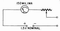
Fig. 312. Simple direct-reading ohmmeter circuit.
It is surprising, however, to find that many ohmmeter circuits use arrangements where the accuracy is unnecessarily dependent upon a specific supply voltage, whether this comes from a battery or the power line. Whichever source of voltage is used, it is desirable that the accuracy of the instrument be almost independent of supply-voltage variations within a workable range.
As an example suppose the ohmmeter, built around a milliammeter with full-scale deflection of 1 ma, is to use a dry-cell unit nominally rated at 1.5 volts. When brand-new these cells give a voltage of practically 1.6, and they can probably be used until the voltage falls to 1.2 before they become seriously unreliable. A circuit for such a meter is shown in Fig. 312. This is a simple series circuit (of the type described on page 41) where equal current flows through each component.
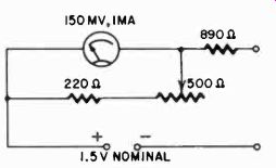
Fig. 313. Increased-accuracy series ohmmeter circuit, using a 220-ohm resistor
in series with a 500-ohm potentiometer to cover the necessary range.
To consider the accuracy of any ohmmeter calibration, the easiest method is to consider what value of resistance will give exactly half-scale reading. In this example, when the battery voltage is 1.6, the total resistance of the circuit to give full-scale deflection of 1 ma, with the terminals short-circuited for zero adjustment, will be 1,600 ohms. Having set the zero point, an external resistance equal to this will reduce the reading to half scale. So, for maximum battery voltage, the half-scale reading should be 1,600 ohms. But on page 42 we called your attention to the fact that when the battery drops to 1.2 volts, the total series resistance for full-scale current deflection, with terminals short-circuited, will drop to 1,200 ohms, so the half-scale reading should then be 1,200 ohms.
The question comes, what reading should be put on the scale at this point? Probably 1,500 ohms, because this is based on a battery voltage at the nominal value of 1.5. But the range of zero adjustment necessary to use the battery over its workable range of voltages means that the value indicated as 1,500 ohms may be anything between 1,200 and 1,600, according to the conditions of the battery.
Increasing accuracy Fig. 313 shows a circuit that reduces this possible error. We start by deciding that the center scale reading is going to be 1,000 ohms.
This means that the total resistance in the circuit, with the terminals short-circuited, must also be as near as possible to 1,000 ohms.
At the maximum battery voltage, this will allow a current of 1.6 ma, while at the lowest battery voltage the current with the terminals short-circuited will be only 1.2 ma. So the meter shunt must be arranged to pass from 0.2 to 0.6 ma at full-scale deflection for zero adjustment range.
Assuming the meter has a full-scale voltage drop of 150 milli volts (resistance of 150 ohms), then the shunt resistor, to pass 0.6 ma, corresponding to the maximum battery voltage, should be 250 ohms; while to pass 0.2 ma, it must be 750 ohms. Using the nearest practical values, a fixed 220-ohm resistor in series with a 500-ohm potentiometer provides the necessary range of coverage.
Now to work out the value of the series resistor: First we need to know the resistance of the meter with its shunt. The actual meter resistance, in this example, is 150 ohms. At maximum battery voltage, when the meter shunt is 250 ohms, the parallel combination of 150 with 250 ohms is about 94 ohms. For the lowest battery voltage condition, the parallel combination, of 150 ohms with 750 ohms, rises to 125 ohms. To ease the figuring, say the variation is from 95 to 125 ohms. Then the average value of the meter with its shunt is 110 ohms. This would be subtracted from the total circuit resistance of 1,000 ohms, which leaves 890 ohms for the series resistor.
In practice, then, the total circuit resistance varies from 985 ohms at maximum battery voltage zero setting to 1,015 ohms when set for minimum battery voltage. So the center-scale reading will always be within 1.5% of its calibrated value.
Accuracy can be increased still further by making the fixed series resistor a greater proportion of the total circuit resistance, using a higher nominal battery voltage so full-scale deflection is still possible. Suppose, for example, three 4.5 volt batteries are connected in series to give 13.5 volts nominal; these batteries will have extremely long life with a maximum current drain of only a little over I ma for full-scale deflection. A terminal voltage variation from, say 11 to 14, could be allowed. The supply voltage is approximately 10 times the previous figure, so the total series resistance in the circuit, to determine the nominal center-scale reading, could be 10,000 instead of 1,000 ohms. Subtracting the mean value for the instrument with its zero adjuster shunt of 110 ohms, this means the series resistor should be 9,890 ohms, and the variation of total circuit resistance is now only .15% from its aver age value of 10,000 ohms. Using the high battery voltage, the inaccuracy due to battery voltage variation is thus much less than the probable inaccuracy in the original calibration of the milliammeter.
Both these circuits are for what we described earlier (Fig. 301) as the "series" ohmmeter circuit, because the resistance to be measured is connected in series with the meter and its supply voltage. It is obvious from the values we have given that it is suitable for measuring relatively high resistances, but could not easily be ' used to measure such resistances as speaker voice coils, which would give a reading indistinguishable from a short-circuit.
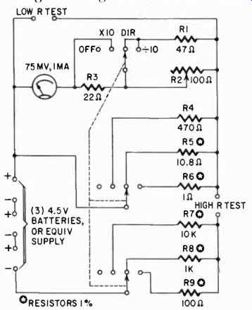
Fig. 314. Accurate multirange ohmmeter, featuring a simplified circuit and
a minimum number of contacts in the switching arrangement. Note that a 75-mv
meter is used in this instrument.
For this purpose a better instrument is the shunt-reading ohm meter, shown earlier in Fig. 302. In this circuit the instrument is adjusted to full-scale deflection with the terminals open-circuit.
When a resistance is connected to the terminals it provides a shunt for the meter, and gives half-scale reading when the external resistance is approximately equal to the internal meter resistance.
Note the word "approximately." Some books omit it in describing this instrument. Assuming that the battery voltage comes from I he original single cell of nominal voltage 1.5, and the instrument is still the 150-mv, 1 ma full-scale job, then at the nominal battery voltage, with no resistance connected, there will be 150 millivolts across the meter and a 1.35-volt drop across the series resistor.
When the meter is shunted with a resistor to bring it down to half scale, there will be only a 75-millivolt drop across it, so the drop across the series resistor must rise to 1.425 volts, which means the current must have risen from 1 ma to nearly 1.1 ma. If the shunting resistor, connected to the terminals, is equal to the meter resistance, this current will be equally divided between them, so the reading will be about 0.55, instead of 0 5 as would be the case according to the statement usually given. To produce half-scale reading a resistor of slightly lower value must be used.
In practice half-scale reading is produced when the external resistance connected is equal to the combined parallel resistance of the meter with any internal shunts, and also with its series feed resistor, as viewed from the terminals of the instrument (regarding the battery resistance as zero).
Now we have the basic requirements for producing an instrument whose accuracy is not to be too dependent on the battery voltage.
The adjustment for full scale, which is zero ohms for the series type or infinity for the shunt type, must adjust the balance of current in the circuit associated directly with the meter movement, without appreciably altering the internal resistance as seen from the instrument terminals.
Using a higher battery voltage improves the possibility for the series instrument. This is true also in the case of the shunt instrument, because the series resistor, although variable, is then always much higher than the meter's own resistance.
Whatever circuit is used, its range is somewhat limited compared with the wide range of resistance values encountered in practice.
To extend the useful range of an instrument it would be good to have a multirange ohmmeter with an accuracy similar to that achieved by multirange testers for voltage and current. Fig. 314 shows a circuit' which has the following useful features:
1. Circuit simplicity-a minimum of special resistors that have to be adjusted to fit the scale.
2. A minimum number of contacts in the switching arrangement.
The latter is particularly important for the lower range readings, because contact resistance can often ruin a reading. In this instrument the number of switch contact decks is reduced by using a strap across the high resistance test terminals for the ranges using the shunt ohmmeter principle.
Zero adjustment
A single variable resistor is used for zero adjustment. Some may feel that it would be an advantage to have an independent zero adjustment for each range, so that changing the range does not make it necessary to readjust for zero. Circuits devised to do this usually have the disadvantage that each adjustment interferes slightly with the others, unless extra switching is employed to disconnect from the circuit the variable resistors not in use. This would increase the number of switch contacts necessary.
In this circuit a variation from that of Fig. 313 is used for the zero adjustment, to enable the same variable resistor to serve all ranges, and to avoid the use of low-value variables, which can cause poor reliability.
With the 3-pole switch in the "x 10" position, the instrument has a center-scale reading of 10,000 ohms, using the HIGH R TEST terminals. To obtain this the series resistor R7 should be just under 10,000 ohms. A 1% resistor of 10,000 ohms should serve here, trimmed, if desired, by setting the instrument to give center-scale reading with a standard resistor of 10,000 ohms. The instrument shunt has a fixed value of 470 ohms (R4), while the zero adjust is a series resistor (R2) of 100 ohms maximum, that varies the voltage drop across the meter branch at full-scale deflection and so varies the current bypassed by the 470-ohm shunt.
The other two switch positions -- the direct reading and the "÷10" position -- give the instrument center-scale readings of 1,000 ohms and 100 ohms respectively. The standard resistors for these ranges are also about 1,000 ohms and 100 ohms (R8 and R9).
1% resistors can be used here, being trimmed to the correct value by obtaining a center-scale reading with a resistance standard of 1,000 ohms and 100 ohms respectively. For these ranges, the meter shunts are R5 and R6, which also serve as resistance standards for the two lowest ranges, using the shunt-ohmmeter principle. For series-ohmmeter operation, the zero adjustment provides- at full scale deflection-a path for the current exceeding the 1 ma that goes through the meter. On the 10" position the total current at full-scale deflection is about 135 ma, so, to conserve battery life, the instrument should never be left in this position for longer than is necessary to take a reading.
The meter that forms the basis of the instrument shown has a resistance of 150 ohms. This was chosen to allow the circuit to be applied to use an old type of meter with some useful life still left in it. Modern meters of 1-ma rating have a lower resistance, or alternatively, for the same resistance a more sensitive meter can be obtained. The limiting factor for the high range is the voltage drop necessary to give full scale deflection through 10,000 ohms.
With a more sensitive meter- for example a 500-microampere job- the same circuit can be used with only half the battery voltage (say 6 volts' worth) and much longer battery life. To use the same circuit with a 1-ma meter of lower resistance value, the simplest method is to build out the meter resistance to suit the values given, so the effective resistance of the meter with a series resistor comes to 150 ohms. This avoids the necessity of recalculating all the circuit values. If a 200-microampere meter should be handy, the circuit could be revised slightly to make it work on only 3 volts' worth of battery. The revision would consist of increasing the resistance values of the zero adjuster and associated switch connections somewhere between two and five times. R4 would also need increasing. The aim in selecting these values is to minimize the readjustment necessary when the range is changed.
For the shunt-connected ranges, giving center-scale readings of 10 ohms and 1 ohm, the positions marked DIR and "÷ 10" are used, with the HIGH R TEST terminals strapped together to give full-scale reading. The resistance to be measured is then connected to the Low R TEST terminals.
To obtain the correct values for the "standards" R5 and R6 on these ranges: R5 is calculated so that with the average full-scale setting of R2, the combined resistance made up of R5, R8, and the meter branch all in parallel is 10 ohms. This procedure is simpler for R6, because the other branches, R9 and the meter branch, are both much higher in value than 1 ohm- the required combined value in this case, for absolute accuracy. If the low-value resistors R5 and R6 are not available, they can be made up of resistance wire.
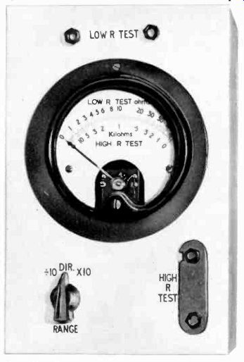
Fig. 315. High-accuracy ohmmeter. The zero control is screwdriver adjusted
through a hole in the case.
As with the series arrangement, the lowest range should be used only long enough to check for full-scale deflection and then to measure the required resistance. Carelessness about this precaution will quickly dispose of a set of batteries.
This can be overcome, for bench work, by using a rectified supply from the power line. A step-down transformer to give an output voltage of 15 to 20, using a metal rectifier to give the right dc output, will provide an energizing supply for this ohmmeter.
The method of zero adjustment will still render it practically independent of supply-voltage variations. Values of RI, R2, and R3 may need adjusting to suit the exact voltage used; also the values of R7, R8, and R9 may need modifying slightly, due to the effective internal resistance of the supply. This can be calculated by measuring the reduction in dc output voltage from the supply when the maximum full-scale current on the lowest range is drawn from it. Dividing this current value into the drop in output voltage it produces will give an effective internal resistance. For example, if the current is 140 ma, and the voltage drops from 16 to 13.2, a difference of 2.8, the internal resistance is 2,800 divided by 140, or 20 ohms. This resistance should be subtracted from the values given for R7, R8, and R9, particularly the last, to keep the center-scale reading correct.
Using the convenient center-scale reading of multiples of 10, the instrument will have a scale of the type shown earlier in Fig. 303, the scale marked HIGH R TEST being used for the readings using series-ohmmeter connections on the upper three ranges and the scale marked Low R TEST for readings on the shunt-ohmmeter circuit used for the two lower ranges, when the HIGH It TEST terminals are strapped together.
The strap for the HIGH R TEST terminals can be made from a metal strip, with two holes drilled to fit the terminal spacing. One of these holes is then slotted out sideways, so the strap can be held by the other hole to one terminal, being clamped on the remaining terminal, or released, according to whether the Low R TEST OR HIGH R TEST is being used.
A photo of the front of the ohmmeter is shown in Figure 315.
The zero control is screwdriver adjusted through a hole in the case.
With television, high-fidelity audio, and other electronic equipment demanding closer-tolerance resistors, this high-accuracy ohm meter is a valuable test instrument.
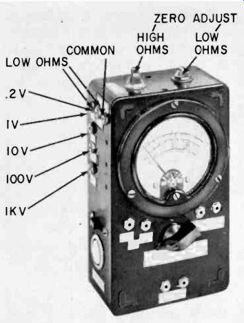
Fig. 316. Pin-jack MINI using a 40-µa basic meter movement (25 k-ohms per
volt).
Pin-jack VOM
Although used in electronics, the VOM can be considered non electronic, since it does not use tubes or transistors. But this limitation can be overcome by using these components to increase the sensitivity, hence the range, of the VOM. [More examples of meter amplifiers are given in section 8.
The basic VOM has important advantages over a vtvm, being more compact and not depending upon a line power supply. Furthermore, there is no warmup period and there are no tubes to age. If, in addition, the instrument has high sensitivity, it compares favorably with the vtvm in the matter of high input resistance.
For example, with a 10-ua movement an instrument has an input resistance of 100,000 ohms per volt. This totals 10 megohms on a 100-volt scale, which approximates the input resistance of a conventional vtvm.
Here is a multimeters using a 40-ua basic movement (25,000 ohms per volt). A number of interesting features were incorporated. The instrument uses phone pin-jacks. (See Fig. 316.) A multipole rotary switch is usually expensive, difficult to wire, and is often the source of mechanical trouble. A low current range was included to measure dc in the order of 1 pa. This uses a transistor amplifier. There are high and low ohms ranges, and two low ac volt ranges. The low ranges are useful when experimenting with junction transistors. There are 15 different ranges altogether. The beauty of the pin-jack arrangement is that more circuits can always he added if desired; the only thing necessary is space on the meter box for additional pin-jacks.
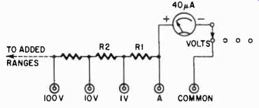
Fig. 317. Voltage-range circuit of the multimeter shown in Fig. 316. This
circuit is in use when selector switch is rotated to the VOLTS tap.
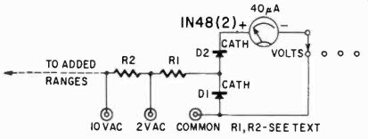
Fig. 318. Circuit for measuring ac volts. This instrument has only two low
ranges-2 volts and 10 volts.
Voltage
Fig. 317 shows the voltage range circuit. It is in use when the selector switch is rotated to the VOLTS tap. To design the volts range we must know the ohms-per-volt value for the particular d'Arsonval movement to be used. If the meter has a full-scale sensitivity of 10 pa, it requires a total series resistance of 100,000 ohms to measure a full scale of 1 volt. This means that the meter is a 100,000-ohms-per-volt unit. In the same way, a 20-ua meter is a 50,000-ohms-per-volt unit.
If you have a 20-ua, 2,050-ohm meter, a series resistance of 50,000 ohms is required for every volt (full-scale) you wish to measure. Therefore, in Fig. 317 you need 50,000 minus 2,050 ohms for R1. For R2 you need a resistor that will drop 9 additional volts.
At 50,000 ohms per volt, this comes to 450,000 ohms. In the same way you can easily calculate all other series resistors. Of course you may not wish to have ranges as marked in Fig. 317. You may prefer 5 volts, 25 volts, or any other. In any case, the computation is the same. You may include as many ranges as you have room for pin-jacks. The ranges you choose, however, should correspond to the markings on the meter scale. If your full-scale reading is 15, you will probably want to use 1.5 volts, 15 volts, 150 volts, etc.
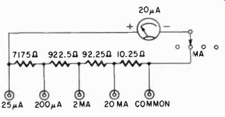
Fig. 319. The Ayrton shunt circuit, used for measurements of current. A ring
of resistors shunts the meter at all times.
To measure volts in Fig. 317, one test lead is plugged into the COMMON or minus pin-jack; the other lead is inserted into the desired voltage pin-jack.
For ac volts, use the circuit shown in Fig. 318. This particular instrument has only two low ranges-2 volts and 10 volts. These have been found very valuable for transistor output measurements. A pair of crystal rectifiers are used across the meter. One half of the ac wave is passed through the meter. The other half is shunted by a crystal and does not flow through the meter.
(When the COMMON pin-jack goes positive, D 1 is conductive and D2 is blocked. Thus current flows through D 1 and not through the meter.) The resistors for these ranges must be found by experiment. This meter has a 40-ua movement. It requires a 2,700-ohm resistor for R1 and 82,000 ohms for R2. The meter resistance is 5,000 ohms.
To measure ac volts, the range switch is left in VOLTS as for dc measurement. The leads are plugged into the COMMON and desired ac volt pin-jack. The rectifiers across the meter have no effect on the other meter ranges.
Current
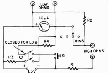
Fig. 320. Circuit for measuring ohms. Dpst slide switch S2, when closed, damps
the meter movement while the instrument is handled, preventing the needle from
bouncing around.
Measurements of current are made by using the Ayrton shunt circuit (Fig. 319). The meter is shunted at all times by a ring of resistors. One test lead is inserted into the COMMON ma pin-jack, the other into the desired current pin-jack. (The formula for the Ayrton shunt circuit was given earlier and appears on page 49.) Fig. 319 shows a network which can be used for a 20-ua movement with a meter resistance of 2,050 ohms. First we must decide on the lowest current reading we want. Let it be 25 pa. We must then shunt 5 pa around the meter and permit the other 20 pa to flow through it. If the shunt resistance is four times the meter resistance, the requirements are met. Therefore Rt must be 8,200-- we know that R,,, is 2,050 ohms. In this case n equals 1.25. For n equals 10 (full scale reading of 20 ua) Rt is 1,025 ohms, etc. In this way, the remainder of the network can be calculated. As with volts, we can add as many ranges as we desire, the only limiting factor being the space we have for more pin-jacks.
One question may come up here. The constructor may wish to use the lowest possible current range, for example, 20 ua in the previous case. This is not possible with a ring shunt. To do this, switch the instrument to VOLTS to disconnect the shunt, and insert your test leads into pin-jacks which connect directly to the meter terminals. These are shown as jacks "A" and "COMMON" in Fig. 317.
Ohms The ohms network is a little more complicated than either current or voltage circuits (Fig. 320). Of course the meter you use must carry ohms scales, as well as volts and ma.
To design the high ohms network, note the ohms reading that corresponds to meter midscale. In this particular meter it happens to be 30,000 ohms. With HIGH OHMS pin-jacks shorted we want full-scale (or zero ohms) deflection. With 30,000 ohms across the pin-jacks we want mid-scale reading. Obviously we need an ohm meter circuit having a total internal resistance of 30,000 ohms (this includes meter resistance). This circuit can be traced in Fig. 320 as follows: R1 is the series resistor, in series with the HIGH OHMS pin-jacks (when the selector switch is on ohms), the battery, and the meter. When the pin-jacks are shorted we want the battery to drive full-scale current through the meter. When 30,000 ohms is placed between the pin-jacks we double the total series resistance, therefore we halve the meter current.
This completes the high-ohms circuit except for one problem.
What if the series resistance (30,000 ohms for our particular meter) is not correct for securing full-scale deflection? It may be too large or not large enough. In our own case it was not large enough. If you calculate the flow due to 1.5 volts through 30,000 ohms you will get 50 ua, yet we are using a 40-ua meter. Then all we have to do is add a shunt, R2. If R2 is 4 times as large as the meter resistance (5,000 ohms) it would pass 10 ua when the meter flow is 40 ua. This satisfies all conditions and our high-ohms range is complete. On the other hand, it is possible for the series resistor R1 to be too large. It may not permit sufficient current to fully deflect the needle. Then the battery voltage must be increased. Add cells until R1 is just right or until it permits too much current flow through the meter. Then add a shunt as just described.
For convenience, R1 is shown as a single unit. However, it should be composed of a variable portion and a fixed portion.
Thus we can compensate for an aging battery. The variable resistor may be about 20% of the total. In this case, R1 should be 26,000 ohms because the meter (5,000 ohms) is shunted by R2 (20,000 ohms). The solution was to use a 24,000-ohm fixed resistor in series with a 5,000-ohm potentiometer. The potentiometer is adjusted by shorting the pin-jacks and setting for full-scale deflection.
The low-ohms circuit includes a push-button switch S1 and a dpst slide switch S2. On this range, zero ohms is at the extreme left and the scale reads upward. Again note the ohms reading that corresponds to mid-scale on the meter. In this case it happened to be 16 ohms. This gives the value of R3, a shunt resistor placed across the meter terminals and the low ohms pin-jacks, when S2 is closed.
With the push-button switch, S1, also closed, R4 permits current flow from the battery into the meter. With the Low OHMS pin-jacks left open, this current must be sufficient to produce full-scale deflection. Then if we place 16 ohms across the jacks we find that the reading drops to mid-scale as required. The smaller the resistance across the pin-jacks, the lower the meter reading.
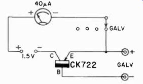
Fig. 321. Galvanometer circuit for measuring weak currents or voltages.
High accuracy is not required here, but high sensitivity is. Now for the design work. In most cases R3 is so much lower than the meter resistance that the latter may be ignored. In any case we want the resistance across the pin-jacks to equal the mid-scale ohms reading (16 ohms). The limiting resistance, R4, produces full-scale deflection when the pin-jacks are left open. Calculate the total current flow when the meter shows full-scale deflection. The meter would pass 40 ua, of course. The 16-ohm shunt would pass 5000/16 or 312 times as much. This is 12.5 ma, so we may ignore the very much smaller meter flow. How much series resistance do we need to permit 12.5 ma from a 1.5-volt battery? The answer is 125 ohms, of which we already have 16 ohms between the meter terminals. Therefore R4 should be about 110 ohms. As before, it should be partly variable. A 91-ohm fixed resistor in series with a 30-ohm potentiometer was used. To adjust this range, leave the pin-jacks open and adjust R4 for full-scale deflection. Be sure S2 is closed and depress the push-button when you make the measurement.
The slide switch serves another useful purpose. When left closed it places 16 ohms across the meter. This damps the movement and prevents the needle from bouncing around while the instrument is being handled. This is not necessary when the meter is used for volts, ma, or high ohms.
Galvanometer
This range measures weak currents or voltages. High accuracy is not required for most of these measurements, but high sensitivity is. Fig. 321 shows the schematic. The input current or voltage is impressed across the GAT V pin-jacks.
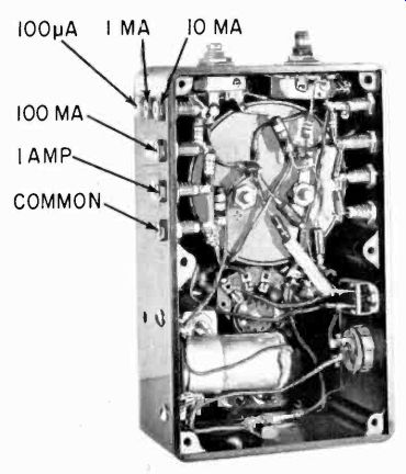
Fig. 322. Interior view of multimeter having four functions: volts, current,
ohms and galvanometer. Common terminal, used for volt range, requires no shunt
or external circuit across the meter.
Present-day transistors don't have uniform and identical collector current flow. For the galvanometer application, the transistor should show low current when the input terminals are left open. This eliminates the need for an auxiliary circuit to balance out and zero the meter deflection when no input is applied. The transistor used here shows only 4-ua collector current with the terminals open.
To calibrate the galvanometer range, apply various known currents between base and emitter. The emitter is the positive terminal. Linearity will not be perfect but it should be very good. This instrument shows a 4-ua deflection for each pa fed to it, giving an easy and convenient method for increasing the sensitivity of a dc meter.
To read volts, add a resistor in series with the negative (base) lead. Use a 1-megohm series resistor, and the meter will deflect approximately 4 ua for each volt applied. For better accuracy, draw a curve or chart plotting pa meter deflection vs ua input (or volts input). To increase sensitivity, use a larger collector battery.
This multimeter has four functions: volts, current, ohms, and galvanometer. Ordinarily this would require a 4-position, single pole switch, not a very common part. Use a 3-position switch for this purpose such as a Centralab unit with 4 terminals. Originally the tap could contact only 3 of them, the "common" terminal being excluded. By filing off the stop, the movable tap could also touch the common terminal- and we have a 4-position switch.
This common terminal is used for the volt range, the only one that does not require a shunt or external circuit across the meter.
(An interior view of the completed instrument is shown in Fig. 322).
Also see: Link | --Guide to VOMs and VTVMs