In contrast to kit type instruments, which generally come in only a few sizes, commercial types appear in a great variety of models, ranges and sensitivities. Some kits are also available in wired form for a somewhat higher price. A properly wired kit should have at least the same quality as a factory wired unit.
There is no practical way to divide or classify volt-ohm-milliammeter except by size and sensitivity. But some of these instruments are both small and sensitive. For example, the unit shown in Fig. 501 is about the smallest of this type available. The 100 micro-amp-meter gives the instrument 10,000-ohms-per-volt sensitivity on both ac and dc. Making the unit so small has required some sacrifice. This is a pin-jack type of instrument, with some internal function switches operated by the ends of the pin studs.
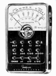
Fig. 501. One of the smallest commercial instruments available. It has a sensitivity
of 10,000 ohms per volt on both ac and dc (Simpson Electric Co.)
The studs are partially threaded, making changing ranges some what slow. The ranges of the instrument show clearly in the photo, and you can see there is no current measurement feature available.
Ohms mid-scales are 120, 1,200, 12,000; the maximum legible resistance measurement is 10 megohms.
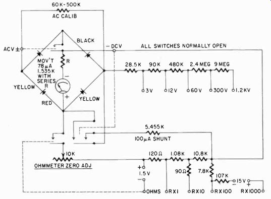
Fig. 502. Circuit diagram of the tester shown in Fig. 501. The internal switches
are operated by the test-lead pin jacks. The ohms range is extended to R x
1,000 through the use of a 15-volt battery.
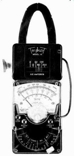
Fig. 503. Volt-ohm-milliammeter with a clamp-on trans former attachment. (Triplett
Electrical Instruments Co.)
Fig. 502 shows the schematic diagram of the entire instrument.
Its basic simplicity is obvious. Notice the internal switches, operated by the insertion of test-lead pins. Another somewhat unusual feature is the full-wave bridge rectifier, allowing the same sensitivity on both ac and de.
Very slightly larger, but with several more ranges is the model shown in Fig. 503. This instrument has, in addition to the voltage and the ohms ranges, four current ranges-0.6, 6, 60 and 600 milliamps. The basic meter is a 50-microamp movement; sensitivity is 20,000 ohms per volt on dc; 5,000 on ac. The ranges are switch-selected, a convenience seldom encountered in instruments this small. Mid-ranges of the ohms scales are 200, 2,000, 20,000 and 200,000. The tester is actually equivalent, in ranges, to most full size VOM's. In Fig. 503, the VOM is shown in combination with a clamp-on ammeter adapter. This adapter is, in essence, a transformer with a core which can be opened, so that it can be clamped around a cable or wire, making the cable the primary of the transformer, one single turn only.
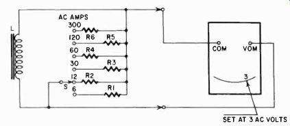
Fig. 504. Schematic of clamp-on transformer attachment of the VOM in Fig.
503.
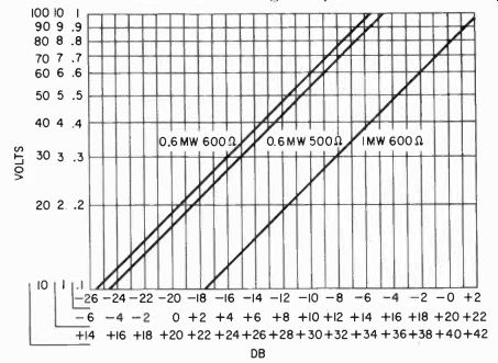
Fig. 505. Conversion curves used for converting the ac voltage reading to
dB's.
Fig. 504 shows the schematic of this clamp-on transformer attachment. Its output is connected to the VOM, and this is set to the 3-volt ac range. Current ratings of the model are 6, 12. 30, 60, 120 and 300 amperes. The adapter can be used with any VOM which has 5,000-ohms-per-volt sensitivity on ac and a 3-volt scale.
Neither of the units shown in Fig. 501 or Fig. 503 have db scales.
But because an output measurement is simply an ac voltage check, using the conversion curves shown in Fig. 505 you can convert the ac voltage reading to db's for any of the three references normally in use-0.6 mw across 500 or 600 ohms and 1 mw across 600 ohms.
The accuracy of this type of instrument is generally about 2% to 3% of full scale for dc measurements and 5% of full scale for ac. This is the accuracy guaranteed by the manufacturer. but in actuality most instruments do better than that. They should, for 5% of full scale means that this is independent of the position of the pointer on the scale. Thus, if you are reading 2 volts on the 2.5-volt ac scale, you may actually have 1.875 or 2.125 volts. But it you read 0.25 volt, the actual voltage may be 0.125 or 0.375, and this may make quite a difference. For this reason, it is always recommended to use the range which will give the highest deflection for that voltage.
One way to cut down possible error is to read as long a scale as can be available, and this is one advantage of the larger instruments. The scale of the 4 1/2-inch meters in larger VOM's is almost twice as long as in the small pocket instruments.
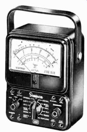
Fig. 506. Typical VOM in the large-size group. (Simpson Electric Co.)
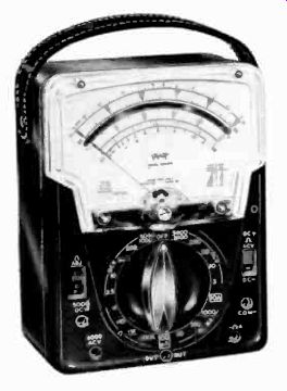
Fig. 507. rout similar to Fig. 506 in ranges, sensitivity and size. (Triplett
Electrical Instrument Co.)
A typical VOM of the larger size is shown in Fig. 506. Similar in ranges, sensitivity and size is the model shown in Fig. 507. These 20,000-ohms-per-volt instruments are the type most often used in radio and TV service; they are general all-around useful tools.
Fig. 508 shows the circuit diagram of the VOM illustrated in Fig. 507. This, as you can see, is an instrument of the type we have al ready discussed extensively. The ac rectifier is the familiar half wave bridge. A convenient feature is S2, a polarity-reversing switch.
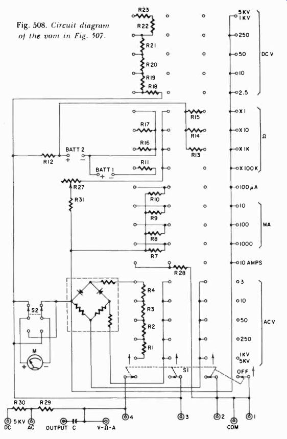
Fig. 508. Circuit diagram of the VOM in Fig. 507.
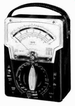
Fig. 509. This accurate VOM has twice the voltage ranges for ac and dc by
using a switch which allows a change of meter sensitivity.
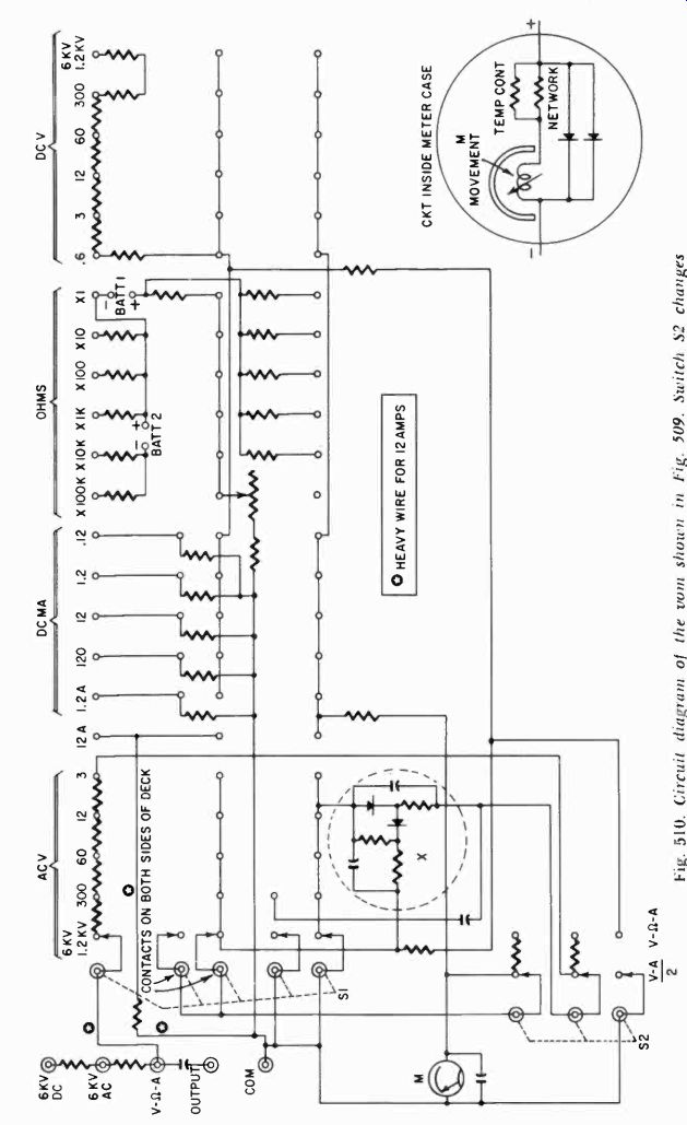
Fig. 510. Circuit diagram of the VOM shown in Fig. 509. Switch S2 changes
meter sensitivity, providing twice the voltage ranges for ac and dc.
This instrument does not use the Ayrton type shunt on the current ranges, but rather individual shunts for each range.
A somewhat more luxurious and a much more accurate instrument is the one shown in Fig. 509, with its diagram in Fig. 510.
This instrument has twice the voltage ranges for ac and dc by virtue of a switch, S2, which allows a change of meter sensitivity.
On the "normal-ranges, those shown on the range-selector switch. switch S2 is in the (V-to-A) position (not as shown). Then the meter sensitivity on dc is 10,000 ohms per volt and, on ac 5,000 ohms per volt. With S2 in the position shown, the meter indicates just half the voltage. In other words, the 12-volt scale now be comes a 6*-volt scale, the 60-volt scale becomes a 30-volt scale and so on. This allows the user always to select a scale on which the voltage will deflect the meter near the top, making for greater accuracy. Having, in effect, twice as many ranges affords twice the opportunity to use a large deflection.
In Fig. 511-a, the "normal" meter circuit is shown in simplified VA form, and in Fig. 511-b the same range for the 2 scale. In the "normal" range, the meter is shunted by resistor R18 to half its deflection and half its sensitivity. R25 is included to allow for the use of the same double system on both ac and dc.
Figs. 511-c and d show the "normal" and "sensitive" positions of the ac voltage range in a simplified schematic. Again you can see that the meter is shunted, this time by R19, while R25 is in series with the meter and R24 in series with the rectifier. This instrument uses a 40-microamp meter; 120 my, in other words, with an internal resistance of 3,000 ohms. However, the lowest V.A, current range (in the 2 the sensitive position) is 60 pa, and the meter is always shunted by a resistor.
Millivolts can be read on this meter simply by using the lowest current-range setting of the selector switch, at which reading the meter shows 120 millivolts full scale with S2 in the "sensitive" position. In the normal position of S2, with the selector still in the 0.12-ma range, the instrument will read 240 my full scale.
In the diagram, Fig. 510, an insert shows a circuit inside the meter. This consists of two items. In the first place there is a thermal compensating circuit, consisting of two resistors carefully selected for their temperature characteristics. Now if the shunts of the meter should get warm, and the meter shows a higher current than normal because the shunt resistance rises, this difference is made up by the increase in the resistance of these special resistors, so that the meter indication remains the same. For the voltage ranges, this circuit is of little importance since the resistors in series with the meter are so high that a small change will not materially affect accuracy. But a change in the current shunts, of course, will matter.
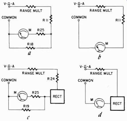
Fig. 511. A simplified diagram (a) of "normal" ranges for dc voltage
for the meter shown in Fig. 509. A simplified schematic (shown in b) with switch
S2 (refer to Fig. 510) in the [V A] /2 position, removing the meter shunts
and giving double the range sensitivity. The ac voltage circuits (c) as they
appear in the "normal" position. with meter shunts. The ac voltage
ranges as they would be (d) in the "sensitive" position of switch S2.
The second circuit shown in the meter case consists of two special germanium diodes. These have a high forward as well as back resistance, but have the characteristic that when a high voltage beyond a certain point is applied, the diode temporarily breaks down and shunts the meter for that moment with a very low resistance. There is one for each polarity, and they are protection for the meter. These meters have been subjected to 1,000 times their normal load without the least damage.
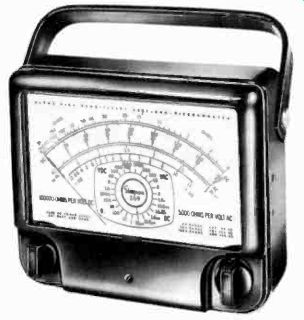
Fig. 512. This 100,000-ohms-per-volt meter features a 10-microampere movement.
(Simpson Electric Co.)
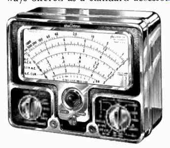
Fig. 513. Less conventional in circuitry, this VOM includes current ranges
in ac. (Phaostron Instrument and Electronics Co.)
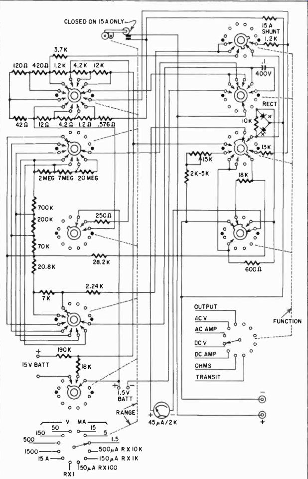
Fig. 514. Complete circuit diag. of Fig. 513.
Other features making this meter a more useful instrument in the laboratory or shop is the availability of external shunts, allowing it to measure up to 30 amperes of direct current. External shunts can of course be made for any meter, but they are not al ways offered as a standard accessory.
Notice that in many of these meters the extra high voltage range has a separate test-lead jack, and so do the high current ranges. The high current ranges, as mentioned before, are designed this way to avoid heavy currents through the switch contacts, while the high voltage range is so arranged to avoid having to insulate all the switch sectors for such a high voltage. With a separate jack and multiplier, only one point need be insulated, the jack itself (and of course the test lead).
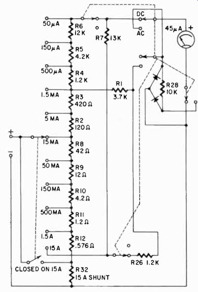
Fig. 515. Current circuit diagram for ac of the VOM in Fig. 513.
Sometimes you will also see a separate jack for the lowest current range. This is a simplification with an added advantage. With a separate jack for the lowest current range, in which the meter is virtually unprotected, the operator cannot by mistake put the current through the meter when switching; he has definitely to disconnect the test lead and reconnect it, a procedure which may give him enough pause to think of what he is doing.
Fig. 512 shows one of the 100,000-ohms-per-volt meters presently on the market. It has a sensitive 10-microampere movement, and in addition is a large 7-inch meter with almost 6 inches of scale length. It is a beautifully designed instrument which will compete in service work with many vacuum-tube voltmeters, but has the advantage that it does not require a power source. For the ohms scales it has the usual dry batteries but, because of its sensitive meter, it is possible to measure resistance up to 200 megohms, with 1.8 megohms center scale. The ranges are clearly marked on the switch-position indicator built into the meter face. In addition, there is a "meter-open" position, which prevents any accidental contact of the test prods from damaging the meter. Apart from the very high values of the multipliers, the circuit for this instrument is conventional.
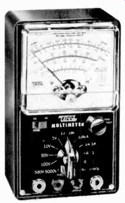
Fig. 516. Typical kit-type multimeter available in wired form. (Electronic
Instrument Co., EICO)
Less conventional in circuitry is the volt-ohm-milliammeter shown in Fig. 513. This is one of the very few instruments on the market which include current ranges in ac. This is accomplished by measuring the ac voltage developed across shunt resistors. The complete circuit diagram is shown in Fig. 514 and the current circuit for ac in Fig. 515. Notice in Fig. 514 that the instrument seems to have very few resistors by comparison with other comparable VOM's. This results from careful design, which allows the use of the same resistor values on the alternating current ranges and the resistance-measuring ranges, for example, and the same multipliers for ac and dc voltages. The rectifier is a full-wave circuit. Sensitivity is 20,000 ohms per volt on dc and 5,000 on ac. The meter is a 45-ua unit, appropriately shunted. The lowest current range is 50 ua.
Selecting an instrument
What has been described in this section so far is just a sampling of instruments on the market. It is obviously impossible to show even a good complete cross-section of all of those available. Besides the many excellent domestic volt-ohm-milli-ammeters, many good instruments at competitive prices are being imported. Whatever instrument you purchase, though, uses all the principles we have discussed, and on the basis of what you now have in the way of information about meters it should be easier to select the proper one for your work.
One type not shown in the lineup, for example, is the less-sensitive commercial instrument equivalent to the kit type meters we discussed. Some kit type meters are also offered in wired form by the manufacturer. A typical example is shown in Fig. 516. This instrument also has current ranges for ac and uses a 400-ua meter.
Sensitivity is 1,000 ohms per volt (shunted meter) on both ac and dc, and the instrument has a special low ohms scale with 55 ohms center scale.
Which meter you select for your job will depend entirely on your budget and the demand of the job. If your VOM is going to be your constant tool, used on every job, you will want a meter which can do all you need it to do. An inadequate instrument would, in the long run, cost you money by forcing you to make inaccurate measurements and guesses, and by generally slowing your work. The additional investment in a better meter is often justified. On the other hand, if your major activity involves appliances, an occasional use of the meter, or simple continuity checks etc., there is no point in investing a great deal of money in a sensitive instrument. An intelligent choice is up to you.
Operation of the VOM
Leery kit type instrument and commercial VOM will come equipped with complete operating instructions. Most of them also include the instrument schematic, and some of them even break down the circuit to show each function in detail. Practically all show how to use the instrument for the measurements indicated on the scales, and many of them also show how to measure other items, such as the capacitance of a limited range of capacitors, etc. This particular subject we will discuss in subsequent sections.
Also see: Link | --Guide to VOMs and VTVMs