No VOM can be economically made which can measure every thing, and both manufacturer and user must, at some point, determine its limitations. This does not mean that forever there after it is limited to certain ranges, nor that it would have to be remodeled drastically. Many of the means for instrument modification (such as extending ranges) can be used externally. Some of these are offered commercially, but all of them can, With some care, be home-made.
Measuring higher voltages
One of the most common tests beyond the VOM's normal range is the measurement of high voltages, found in scopes, transmitters and special electronic equipment. To provide the necessary higher value of multiplier resistor, and to make it a convenient accessory to use, this resistor can be built into a probe especially designed to protect the user from high voltages. Commercially these probes are offered so that the range of the VOM can be extended to as much as 60 kilovolts.
It isn't practical to try to cover all ranges adequately with a single probe; remember that the recommended method of reading the VOM is to get as much deflection as possible. For this reason as many as three probes for higher dc voltages and two for ac are needed. These can come in ranges of 10, 25 and 50 kv for dc; 10 and 25 khz for ac high-voltage measurements. (Some VOM's are designed to measure as much as 6,000 volts dc without the need for an external probe.)
The high voltage probe for dc
What does such a probe consist of? It is nothing more than a precision resistor of very high value, matched to the input resistance of the instrument. On any range the measurement must be made to deliver an exact multiplication of the scale values. Consider, for example, dc volts on a 20,000-ohms-per-volt meter. The total resistance in the circuit on the 2.5-volt range would be 50,000 ohms. To read, say, 10 kv using a resistor which does not go out of sight in resistance value, you would want a total of 200 megohms. For this a 200-megohm resistor would be accurate enough, the meter and multiplier resistance of the instrument being very insignificant. The resistor, for convenience and safety, is enclosed in a plastic case which, for these voltages, usually has either ribs on the end to prevent flashover of the high voltage to the operator's fingers or an extended handle to make it safer to use. Fig. 601 shows a typical high-voltage probe.
Since most high-voltage supplies such as those in TV sets can deliver current in microamperes only, or at the most a milliampere or so, it would not be profitable to try to make high-voltage probes for anything but sensitive instruments, preferably at least 20,000 ohms-per-volt. Anything less than that might load the source sufficiently to lower the voltage and give a false reading.
It is feasible to make the resistor, such as the 200-megohm probe just described, from 10 20-megohm units, but remember that the resistors, if they are from the same batch, can very well have the same error, and this error will be multiplied by 10 also. Make certain that your resistors are accurate originally, or measure them as accurately as possible, so that you can either add or eliminate some resistance to obtain accuracy.
The high-voltage probe for ac High-voltage probes for ac are made in the same way, provided you can assume that the frequency at which they are to be used is one at which the rated ohms-per-volt of the instrument is valid.
At higher frequencies, you may have to know the impedance of the instrument on the range you wish to use. (The method for determining this will be described later.) Certainly, through the audio range you can expect that your VOM will maintain its ac curacy and, for some commercial instruments, well beyond this.
Make certain that the insulation around the probe is sufficient to withstand the high voltage. For 10 kv at least 2 inches of clean phenolic or Plexiglas-type plastic should separate the high voltage from your hand, with proportionately greater distances for higher voltages.
The ranges of VOM's are almost always sufficient to cover every thing but very high voltages. However, if an intermediate point is needed, the process of obtaining it is the same, except that not so much high-voltage insulation is required.
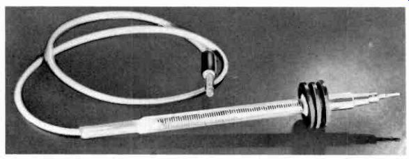
Fig. 601. Home-made high-voltage probe. The purpose of the ribs is to help
protect the user against high-voltage arc-over. The resistor (or resistors)
in the probe act ac an external series multiplier. For use with a probe of
this sort, the VOM should have a minimum sensitivity of 20,000 ohms per volt.
Measuring lower voltages
Since the VOM is a current meter in the first place, converted for measuring voltages by adding series resistors, there is no reason why the process cannot be extended to include lower voltages by using the lowest current range of the instrument together with an external multiplier resistance. For example, in a 20,000-ohms-per-volt meter the basic movement is a 50-ua unit. If the internal resistance of this meter is 2,000 ohms, voltages as low as 100 milli volts can be measured by using the meter directly. Proportionately higher voltages would then require small series resistors. Thus the same meter would have a full-scale range of 250 millivolts with a series resistor of 3,000 ohms (5,000 ohms minus the meter resistance). With such low series resistors, the meter resistance must be taken into account. If the meter circuit resistance is not known, you can determine it by the same method described in detail in Section 2.
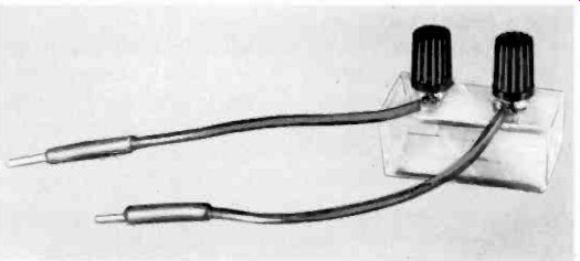
Fig. 602. Home-made external meter shunt for the von. It consists of a plastic
box with a resistor inside, two binding posts and short leads to the meter.
The leads form part of the shunt resistance and must be calculated as such.
This has an advantage in that you can adjust the shunt to its proper value
by trimming the length of the leads.
Adding current ranges
Naturally, there is no way to make the instrument read a lower current than the basic meter rating, unless we amplify the current.
One method was described in Section 3 and will also be shown in a later section. The meter ranges can be extended tremendously by making external shunts for the VOM. All that is needed is a resistor of the proper value, some short leads to attach it to the meter, and two jacks to plug in the test leads of the instrument. Fig. 602 shows a home-made external shunt. It can be mounted in a small utility box to give it a neat appearance, and marked with the current range for which it is designed. To determine the shunt value, treat the entire meter circuit (what ever it may contain internally) as the basic meter, and determine the proper shunt value by the half- or part-deflection method as explained for the basic meter in Section 2.
External shunts are made by some manufacturers of commercial VOM's. One instrument has a shunt which will extend its current-measuring capability up to 100 amperes dc.
The clamp-on ammeter described previously can be used to provide current ranges down to 6 amperes ac. To make your own clamp-on ammeter is a difficult and exacting job, and is not recommended. Fortunately, there are simpler ways to provide your own current ranges for ac.
A current will develop a voltage across a pure resistance which is exactly proportional to the current and the resistance. There is really no such thing as a pure resistance, since even a straight wire has some inductance, but for practical purposes we can regard most resistors as pure enough over a wide frequency range.
To measure alternating currents, then, we need precise resistors capable of carrying (without undue heating) the currents we need to measure. The wattage rating of the resistor should be many times the power to be dissipated in it, unless we make a low temperature coefficient resistor of Manganin wire. A 100-ohm resistor, with 10-ma, rms alternating current through it will develop 1 volt rms. Thus, on a 3-volt scale, we could read from 0 to 30 ma ac.
However, this method has a practical limit. Were we to try to measure the current through a 6.3-volt pilot bulb in this way we would find that the bulb would light only dimly (if at all) on a 6.3-volt supply. To measure bulb current, the bulb must get normal voltage. This we can do by using a higher supply voltage and adding series resistance until the voltage across the bulb measures 6.3, then changing our test leads to the standard and measuring the voltage across it, and from that we can calculate the current normally required by the bulb. The method is illustrated in Fig. 603. The lower the lowest available ac voltage range on our meter, the better it will be for measuring alternating currents by this method, provided we maintain accuracy.
In most commercial meters, the ac section is not accessible to the outside of the instrument, so to circumvent the lowest ac multiplier you would have to dig into the instrument and provide a separate connection. This cannot be recommended, particularly on an expensive commercial meter.
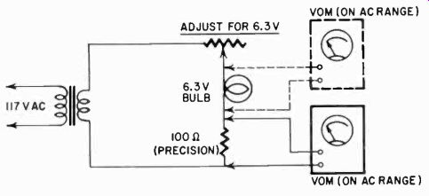
Fig. 603. Measuring alternating current using the ac voltage ranges of the
VOM. The bulb and the fixed precision resistor are in series. The transformer
is a step-down type but must be able to supply enough voltage to take care
of all the IR drops. Most voiles do not have a provision for reading alternating
current directly.
Measuring higher resistances
The usefulness of almost any VOM can be increased with a simple, easily built range extender. At the beginning of Section 3 we described the operation of two basic circuits- series and shunt. In the series version the battery, meter and some resistance are connected in series between the test leads. The circuit is open until an unknown resistor is connected across the leads. This completes the series circuit, the current flow depending upon the battery voltage and circuit resistance. The meter reads full scale with the leads shorted. (The zero adjustment is made to an exact full-scale reading.) The meter will read half-scale when the test probes are connected to an external resistance equal to the internal resistance of the ohmmeter. This half-scale reading is the true criterion of the sensitivity of the instrument. Any ohmmeter, regardless of sensitivity, reads from zero to infinity. But, when the internal resistance is equal to the external resistance, the current will be half the full-scale value and will show the reading at which the scale is most spread out and therefore most useful.
This method is accurate for practically all purposes for which a meter would be required in radio-TV service work. But it is worth noting that a slight error is introduced, because the resistance of a meter with a shunt connected across it is lower than that of a meter alone. This error is usually less than 1%.
The other circuit, the shunt version, shows exactly the same action in reverse. In it the circuit is closed all the time, and full scale current flows through the meter except when an unknown resistance is connected across the test leads. Lower values of un known resistance shunt more of the current, the meter reading zero when the leads are shorted. In this circuit also, we get a half-scale reading when the external resistance is equal to the internal.
In the series circuit (refer to Fig. 301 on page 41 of Section 3) the internal resistance is equal to the total resistance of the battery, meter and variable resistor. In the shunt circuit (see Fig. 302 of Section 3) it is the value we see looking in through the test leads and is equal to the parallel combination of the meter resistance and the series combination of battery and rheostat resistance.
To increase the sensitivity of the series circuit add more battery voltage and more internal resistance so that you still get a full scale reading when the leads are shorted. You can make up this battery and resistance in a separate package, convenient to handle and use.
Although it is less obvious, the same thing is true of the shunt circuit. In both cases the improvement will be proportional to the increase in voltage and resistance.
The first step is to examine the ohmmeter. Determine which circuit it uses, the battery voltage on the highest scale and the half-scale ohms reading. This is the point where the meter movement shows half-deflection. For a 10-times increase in sensitivity, 9 parts more each of voltage and resistance must be added in the same proportions. For an increase of 100 times, 99 parts more of each.
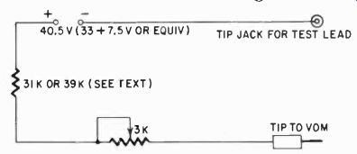
Fig. 604. Range extender for use with an ohmmeter using a 4.5-volt battery
and a shunted 1-ma meter, and having a mid-scale sensitivity of 3,600 ohms.
Building the extender
The simplest sort of range extender is shown in Fig. 604. It is intended for use with an ohmmeter using a 4.5-volt battery and shunted 1-ma meter, and having a mid-scale sensitivity of 3,600 ohms. The addition of a 3,000-ohm resistor and 40.5-volt battery (in series-aiding) provides a 10-times increase in sensitivity, to a mid-scale reading of 36,000 ohms. The total voltage and the total resistance of the circuit are now each 10 times as high. For the probably more common series type ohmmeter the resistance should be 39,000 ohms, and the constants will have to be varied for instruments using other meters, battery voltages, etc. For example, the resistance values would be doubled with the same voltage if the meter were a 500-ua type, and an ohmmeter with a 1.5-volt battery would be multiplied 10 times by adding an external voltage source of 13.5. With a 1-ma meter, this would mean about 12,000 ohms fixed resistance and a 3,000-ohm potentiometer in series. Multipliers for ohmmeters with unknown internal circuits can be found by experiment, being careful not to use too much battery or too little resistance at the start. A little time spent changing resistors may save an expensive meter.
There are several ways to make a VOM read resistances above its highest range, and they are very simple ways. One of them is illustrated in Fig. 605, a simplified diagram of an ohmmeter circuit.
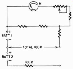
Fig. 605. Method for reading high values of resistance. The VOM is set on
its lowest current range and is connected to a high-voltage dc source. To protect
the meter, set it on a high-current range and work the range switch back until
you be gin to get a deflection on the meter. A safer method would be to increase
the amount of high voltage gradually.
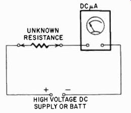
Fig. 606. Method for reading very high resistances. With a battery or dc supply
of 500 volts, you can accurately read 50 megohms.
Suppose that the battery in this circuit is 6 volts, and that the meter on its highest range reads 180,000 ohms mid-scale. This means that the meter circuit contains 180,000 ohms. If you add an external battery and an external resistance of 180,000 ohms, you can still zero set the meter but then you have exactly doubled its range. And for greater multiplication you can use higher battery voltages and greater resistors on the outside.
For very high resistances, this method becomes somewhat impractical. In such a case, simply follow the scheme shown in Fig. 606. If the meter has 50 ua as its lowest range you can comfortably and fairly accurately read a current of 10 ua. This means that with a battery of 500 volts, or a dc supply of that amount you can accurately read a resistance of 50 megohms. Or, if you want to squeeze a bit, reading 5 microamperes, a resistance of 100 megohms. If that is not enough, you have to use a higher voltage supply, but handle the test leads carefully. Only for devices such as ionization chambers and electrometers and to design high- voltage probes for VOM's would you want to go that high. Thus, for the 200-megohm resistor discussed earlier as the multiplier in a high-voltage probe, you would have to use a 1,000-volt supply, or read a lower current.
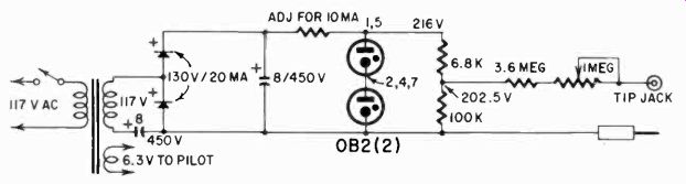
Fig. 607. A more elaborate range-extending method, using an electronically-regulated
power supply.
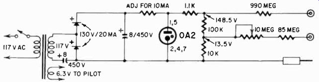
Fig. 608. This extender provides multipliers of 10 and 100 for a typical vom,
having a shunt circuit with a I.5-volt cell, a series resistance of 10 megohms
and a virtually infinite impedance meter circuit.
In Fig. 607 we have a more elaborate version using an electronically regulated power supply, providing a 10 times increase in sensitivity for an ohmmeter using a 50-microampere movement, a 22.5-volt battery and having a mid-scale sensitivity of 450,000 ohms. The required 202.5 volts is obtained from a tap on a bleeder across the regulated 216-volt drop provided by a pair of 0B2's in series.
The extender shown in Fig. 608 provides multipliers of 10 and 100 for a representative VOM, having a shunt circuit with a 1.5 –volt cell, 10 megohms of series resistance and a virtually infinite impedance meter circuit. Assuming that our instrument has a mid scale sensitivity of 10 megohms the extender provides 100 and 1,000 megohms and can be used for reading to at least 10,000 megohms. It is connected so that it bucks the internal battery of the ohmmeter and the meter reads downward when the leads are shorted.
Here the supply voltage is 9 times and 99 times the original 1.5 volts. The resistors are in proportion, which produces the proper ratio of 1.5 volts to 10 megohms. No zero adjuster is used on the highest scale; instead, series resistors are selected so that the short circuit reading will be approximately correct. In fact, the rheostat may be omitted from any of the circuits shown if they are adjusted carefully and if the original ohmmeter has a good range of zero adjustment.
Above 100 megohms we rarely deal with the resistance of conductors. We usually measure the resistance of insulators that have significant voltage and temperature coefficients. Surface moisture also enters, particularly as dirty surfaces often carry perspiration salts from handling as well as other substances which draw moisture from the air. Consequently, insulation resistance measurements cannot be compared, repeated or even specified except in terms of test voltage, ambient temperature and atmospheric humidity. And even then, a repeatability within 5% or 10% is good.
In building the unit of Fig. 608, the tip jacks must be well insulated by locating them in a panel of good insulating material like polystyrene, with an inch or two of creepage path to metal. A range switch must be specially designed; ordinary switches have too little clearance and may even have cracks between laminations to hold films of moisture or dirt. Special resistors are required. A variable zero adjustment is not too easy to make, but the zero can be brought slightly on-scale by adding series 10- or 22-megohm resistors at the supply end where they are easier to insulate. Insulators and resistors should be handled with clean gloves and care to avoid fingerprints and scratches.
Measuring lower resistance
There is nothing you can do to the built-in ohmmeter circuit to change it for reading a lower resistance range, but you can again use the current ranges of the meter. For example, if your meter has a current range of 10 amperes full scale, send a 10-ampere current through it. Maybe this is not exactly 10; maybe it is only 8 1/2 amperes. Next, take a known resistor (which you can measure on your ohms ranges) and put it in series with the meter and the reading is now, say, 5 amperes. The ratio of R. (meter resistance) and R. R is 5 8.5. If this resistor is 20 ohms, we could then calculate the meter resistance as:
Rm/ R. + 20
- 5 8.5 or: 8.5
R. = 5 R, 100
and
Rm = 100/3.5 = 28.6 ohms
This would then be the meter resistance in the circuit. This is an unrealistic figure (it will always be less on the 10-ampere range, more likely something like 0.02 ohms) but the example would be more difficult to follow with such figures.
Suppose you do find an internal resistance on the 10-ampere range of 0.02 ohm? Send 5 amperes through the meter, and then parallel the meter with a low unknown resistor, so that the reading drops to 3 amperes. What is the unknown resistor value? The meter current is now 3/5 of the original current, so the resistor must be passing 2/5. The ratio of the meter resistance and the unknown is 2/3 and the unknown is 3/2 X .02 = .03 ohm; that is, if your voltage remained exactly the same.
If you use an auto battery or a heavy-duty low-voltage supply for your source, you can have reasonable confidence that the voltage, and thus also the current, did not change. But suppose the total current did become less due to a sagging supply. Say it was only 4 amperes. Then the resistance would actually be 3/1 x .02 = .06 ohm, twice as much as you would be figuring! Obviously, this must be avoided. The supply must be capable of delivering this current with no change in voltage.
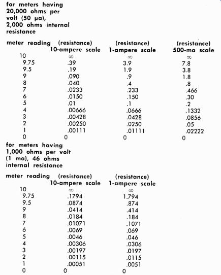
Table 6-1. Using ampere scales for measuring low resistance for meters having
20,000 ohms per volt (50 ua), 2,000 ohms internal resistance; for meters having
1,000 ohms per volt (1 ma), 46 ohms internal resistance
Note: any test leads used are included in resistance measured.
With a dependable current source, however, the VOM high current ranges can be used to read very low resistances indeed, without special gimmicks or scales. All that is needed is to take advantage of the VOM's many possibilities. In a case such as this, the current will have to be supplied (in most cases) through a heavy resistor. Make sure the resistor can carry the current and does not heat unduly, or this again would introduce error. With an auto battery supplying 6 volts, you would need about 1.2 ohms to get a 5-ampere current. The resistor would have to dissipate 5 X 5 X 1.2 = 30 watts (I^2R). If you have a resistor of 25 watts which is wound from a wire with a good temperature coefficient, it will probably do if you read quickly. Remember, you may find a heater or flatiron element which can supply the necessary wire for this, or you can use a length of fairly heavy coiled wire. In the example using an auto battery and the 10 ampere range on the meter, you actually are making a slight error. In the first case, you have .02 ohm in the circuit in series with 1.2 ohms and, in the second case, the two parallel resistors, which works out to .012 ohm. Your total current in the second case is a little more, but the difference is less than 1%, so perhaps this is close enough. If not, you can adjust the ratio to take ac count of this small difference, but the odds are that you are not reading your meter carefully enough for such close figuring. The higher your voltage and series resistor, when you are reading such high currents and low resistances, the less the error due to the actual resistance change in the circuit when you parallel the unknown with the meter. If, in this case, you had used a 12-volt battery and a 2.4-ohm resistance, the difference would have been less than 1A%. Surely you can ignore that.
Here then is a way to measure, with a standard VOM, very low resistances. Table 6-1 shows how the values work out for a typical meter if you start with full deflection and reduce it to half with a parallel unknown resistor. Other values would, of course, be proportional.
If you choose this way of measuring very low resistances, you must also be conscious of the dissipation the unknown resistor must have, but it generally is not very high. In our example, it was 2 X 2. X .03 = .12 watt, and that can be dissipated by a very small resistor indeed.
There are other ways of measuring low resistance, but unless you are willing to set up a special bridge-type circuit, this technique, using only the VOM, a good current supply and a heavy duty resistor, is about the simplest and most convenient.
Measuring capacitance
It might come as a surprise, unless you have a commercial VOM with detailed instructions on the subject, that you can use your VOM for measuring capacitance. Although not as simple as measuring voltages, for you must convert an ac voltage reading into capacitance, the process is not difficult. The reason it can be done is that a capacitor has a definite resistance at a definite frequency.
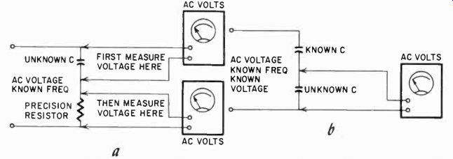
Fig. 609. The vom can be used to measure capacitance . The reactance of the
capacitor is determined first. When this is known, the capacitance can be found
from the standard formula for capacitive reactance or from Table 6.2. In the
first circuit (a), the voltage across the capacitor is compared with that across
a known value of precision resistor. In the other circuit (b), a capacitor
whose value is known is used as the comparison standard.
It takes some energy to charge and discharge a capacitor with an alternating current applied to it. Some energy has to be dissipated in the capacitor. The reactance varies with the frequency; it is low at high frequencies and high at low frequencies. This may sound backward, until you think of the fact that the energy at low frequencies is dissipated over a longer time each half cycle, and thus there is more opportunity for it to dissipate.
The reactance of the capacitor, or capacitive reactance as it is called, relates to the frequency as follows:
1 X, 2 pi fc
in which c is the capacitance, f the frequency and n the well known 3.14 which we use in calculating dimensions of a circle. It is fairly easy to measure capacitance, since we can measure the reactance by determining the voltage developed across it at any one frequency.
The method is illustrated in Fig. 609. The alternating current is passed through the capacitor and an accurately known resistor, and the voltages across the resistor and the capacitor are compared.
These voltages are not in phase, but this does not matter, since you are measuring the voltages one at a time, and only the voltage developed across one element. But don't simply measure one and subtract it from the supply voltage, for then the phase will make a difference.
From the voltage, you can work out the capacitive reactance in ohms, and from this calculate the capacitance with the formula.
You have, of course, a stable frequency available-the 60-cycle power line. This is generally held accurate to within 1/4 cycle by the utility company, and this is close enough for these measurements. Table 6-2 shows the capacitive reactance for a number of popular-size capacitors at various frequencies.
There are several other ways of working out the capacitive reactance in ohms. If your meter has a current range for ac, simply measure the current through the capacitor from a known voltage source, and thus obtain the capacitive reactance. In effect, you are doing what we have just described, but now the standard resistance is built into the meter. In fact, many manufacturers of such meters calibrate a scale for capacitance (at 60 cycles) directly on the meter scale.
Another way to measure capacitance is to replace the resistor with a known capacitor, as shown in Fig. 609-b. Then you will not have to change the meter test leads, for now you know that the two voltages are in phase, and you can get the capacitance more directly if you know the supply voltage. Just subtract the measured voltage from it, and the remainder is across the known capacitor. Then the ratios of the capacitors is the inverse of the voltage ratios. Remember that in the formula for capacitive reactance the letter c appeared in the denominator, meaning that the impedance (and thus also the voltage developed across it) will be smaller when the capacitor is larger, hence the inverse ratio. When you use this method, say across the power line, be sure to start with the 250-volt ac range on your meter. In case the unknown capacitor is shorted, this would then prevent damage to the meter.
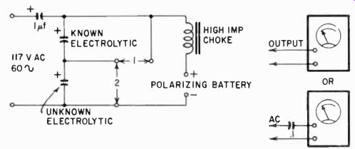
Fig. 610. Method for measuring the capacitance of electrolytics.
It may be necessary to put a blocking capacitor in series with the VOM.
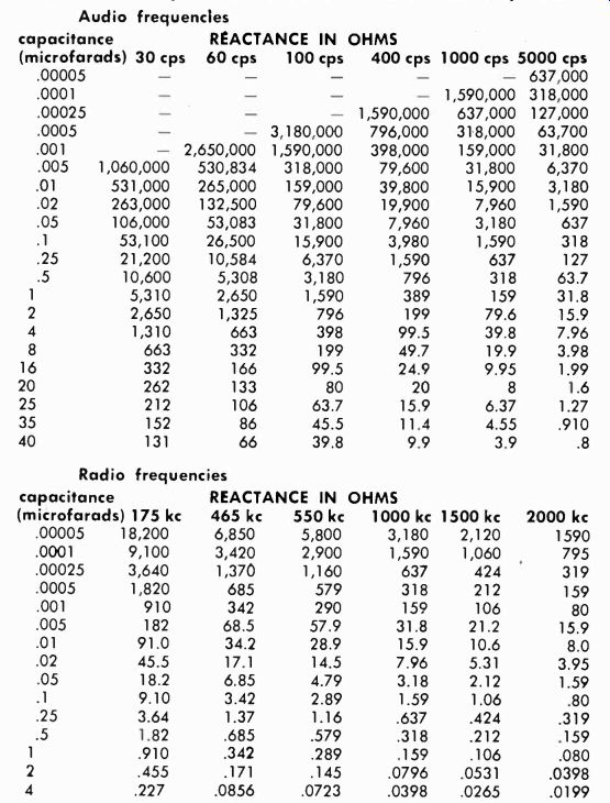
Table 6-2. Capacitive reactance at different frequencies Audio frequencies
A word of caution. Do not attempt to use this method for measuring electrolytic capacitors. They would be damaged by the applied ac, or you might damage your meter.
To measure electrolytics we can use essentially the same principle, but we must use a little more complicated setup, (Fig. 610) invented by Morecroft. The two capacitors, one known and one unknown, are both electrolytics, of approximately similar values. The measurement becomes difficult to make accurately if the units have a capacitance ratio of more than 4 to 1.
The values of capacitance and reactance shown above are common, but not all-inclusive. Values of reactance not listed can be found through simple proportion. For example: a capacitor of 50 pf would have one-hall the reactance of the 25 uf capacitor listed.
A 100-uf capacitor would have one-fourth the reactance of the 25-pf unit. This holds for all frequencies.
In series with the capacitors are two items. In one leg, connected to the ac we see a paper capacitor, of 1 or 2 of. In the other leg, there is a high-impedance inductor and a battery. The battery is necessary to polarize the electrolytic capacitors, since these do not act the same when they are not polarized. Polarizing takes only a few milliamperes' current, so the battery does not have to be large. But it should have at least about 6 volts, preferably more. The inductance is included, because the internal resistance of a battery is not great, and thus the battery would shunt across the capacitors and ruin the measurement. The inductance must be a high value. You can use the primary of an output transformer.
This will have an impedance of about 2,500 to 10,000 ohms but will not significantly affect the capacitance measurement.
Now you can see why we need the paper capacitor. It avoids ruining the battery with an applied ac capable of delivering a large current and avoids pumping dc into the ac source.
With this setup, you can now measure the ac voltages developed across the capacitors. You must, because of the charging current from the battery, have the proper polarity on the electrolytic capacitors. They are marked with a + and a- or "pos" and "neg" on the can or paper sheath. When you measure the ac voltage developed across the two capacitors, unless your meter has a capacitor in series with the ac ranges, it will probably deflect from the battery only. In that case, you must use either the OUTPUT ranges or connect another capacitor in series with the meter.
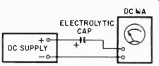
Fig. 611. Technique for checking the leakage current of an electrolytic capacitor.
When you have done all this, the capacitance of the unknown electrolytic can be determined from an inverse relationship. In other words, the ratio of the known capacitor is the inverse of the ratio of the voltages developed across the two. Thus, if you apply 117 volts to the ac terminals (and use a 1-uf unit for the series capacitor) and if you have one capacitor which develops, say, 2 volts ac across its terminals and you know it to be 50 uf, then if the other capacitor develops 4 volts ac you know it is only 1/2 of 50, or 25 uf. The accuracy of this method depends partially on how well you know the known capacitor value, for this is now your standard.
One way to get around this is to use several capacitors. all marked with the same value. Check each one against the un known and then average the readings.
There are ways, of course, to calibrate an electrolytic capacitor for a standard. Although they are not very complicated, the measurement of electrolytic capacitors is not so important that we need bother with it. The way in which electrolytics are used does not call for a critical value.
The Morecroft method can be used with a calibrated setup as well, without a known capacitor, and this is the way it is used in production testing of electrolytic capacitors. But unless you intend to check hundreds of electrolytic capacitors each week, there would be no point in going to all this trouble. In production work, an ac milliammeter is used to measure the current through the single capacitor directly, and an ac voltmeter to measure the ac voltage across it. From these two values the impedance and hence the capacitance can be determined. The ac milliammeter will then be calibrated in-capacitance directly. This is getting out of the area of VOM's and we will leave it at that. But at least you know where the method of checking electrolytic capacitors originated.
One more item about electrolytic capacitors: check the leakage current. This is done with the normal working voltage applied to the capacitor and a dc meter in series (Fig. 611). A good electrolytic capacitor will show 0.3 to 0.9 milliampere of leakage current' per uf per volt. Some poorer ones, but still usable, show up to 1.5 ma per pf per volt. More than this should make you seriously suspect the capacitor or even reject it. A capacitor which shows no leakage is either open or completely dry, and should be tossed out.
[[1. This value is for standard-size units used in ac-dc sets. Tantalum units, used in miniature portables, have a maximum leakage of .07 microampere per pl per volt. Aluminum foil subminiatures have a leakage of 0.1 microampere per Al per volt.
2. Good electrolytics that have been stored idle for a long period of time will show high leakage. Reform these before testing.]]
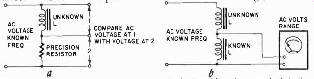
Fig. 612. The value of an unknown inductor can be found by using a method
similar to that for finding unknown capacitance. Either a known value of inductance
or resistance can be used as the comparison component.
Measuring inductance
We can measure inductance by the same method as capacitance but we can now work with direct ratios. Inductive reactance is given by:
XL = 2 pi fl
in which pi is again 3.14, f the frequency and 1 the inductance.
The methods are shown in Figs. 612-a and b. But there is an element of error which must sometimes be taken into account.
Inductances are not always wound from wire which will give them the least dc resistance and, if we have such an inductor. a considerable voltage might be developed as a result of the dc resistance. This is not in phase with the inductive voltage, and the total voltage developed may be a result of these two items. We can find this voltage either by making a vector diagram or by doing some arithmetic. The vector method is shown in Fig. 613.
The resistance of the coil is measured using the ohmmeter section of the VOM. This is drawn as a horizontal line. You will have to decide on the units you want to use. For example, you may wish to let 50 ohms equal 1 inch, or 100 ohms equal 1 inch, etc.
Now draw a vertical line from the point marked 0. This line can be any reasonable length-say, two to three times the distance of the horizontal line. Using the setup shown in Fig. 612-b, calculate the apparent reactance. The value of this reactance will be in ohms. As far as we are concerned, though, it will represent a line whose length is determined by the values chosen for the horizontal line. For example, if we had decided earlier to let 100 ohms equal 1 inch and we had calculated an apparent reactance of 250 ohms, we could say that this is equivalent to a line 2.5 inches long.
Starting at point A in Fig. 613, draw a line of this length between the horizontal (base) and vertical lines. At the point of intersection with the vertical line, write the letter B as shown in the illustration. The distance between B and 0 on the vertical line is the true reactance. Let us suppose that this distance is 1.5 inches. Using the scale we had set up, (100 ohms = 1 inch) the true inductive reactance would be 150 ohms.
For example, suppose the dc resistance is 30 ohms, and we find from the developed voltage an apparent inductive reactance of 50 ohms. Then with our method we will find that the actual inductive reactance is only 40 ohms. We must use this to calculate the inductance with the formula XL 1- 2at Or, if you are good at geometry, you can use the Pythagorean theorem and find true reactance by taking the square root of the difference of the squares of the two measured values:
X1. = V302-31:T2 = 40.
I true I There is a limit to the inductive reactance measurable with 60 cycles. To measure small inductances you will have to use a much higher frequency. But good commercial VOM's can be used up to several hundred khz, and you can actually measure such things as broadcast coils if you use a high enough frequency.
At those frequencies, since there is usually very little wire in the coil, you can ignore the resistive component.
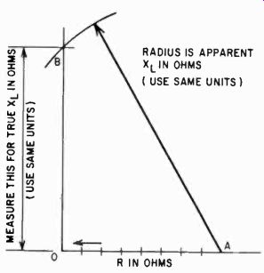
Fig. 613. When a coil has a high value of resistance, an allowance must be
made for this resistive component.
It is easier to measure inductive reactance with higher frequencies because the voltage developed across an inductance is greater, as you can read from the formula. The greater the frequency, the greater the inductive reactance and thus the voltage across it. Here is then another use for the VOM.
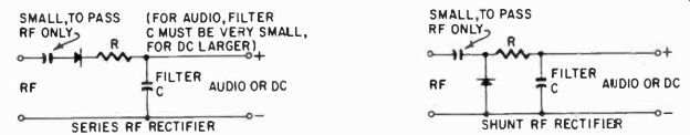
Fig. 614. The ac section of a VOM is not suitable for measuring rf. Higher
frequencies can be measured by rectifying and filtering them. A series (left)
or a shunt rf probe (right) can be made for use with the VOM.

Fig. 615. Waveshapes showing measurements of modulated and unmodulated rf
voltages.
Measuring rf voltages
Most commercial meters are good up to several hundred kilo cycles. At higher frequencies, the reading becomes increasingly less accurate as the frequency goes up. But there is a remedy. You can rectify the rf and measure the resulting dc. This is done with the circuits shown in Fig. 614. These can be built into a probe if you so desire. Here the measurement made depends on the size of the resistor (R) and the capacitor (C); that is, the time constant of the circuit. If the time constant is large enough, the instrument will read a dc voltage equivalent to the peak of the rf wave, whether this is modulated or not. If the time constant is much smaller, but still large for the rf, the instrument can be used to read the modulation voltage on the ac scales. The two situations are illustrated in Fig. 615.
Whether you measure the dc or modulation voltage depends on the choice of circuit elements. With a large filter capacitor, the time constant increases. With a large input resistance the time constant also increases. Unfortunately, there are only a few places, such as in transmitters, where the rf voltage to Be measured is sufficiently high to provide an adequate response of meter and probe, so that other measuring devices are usually needed, such as sensitive vacuum-tube voltmeters and oscilloscopes.
Measuring power
Sometimes it is very informative to know how much power a device is consuming. This can be measured in several ways, one of which is using a wattmeter. However, with the VOM we can also measure wattage in a number of situations. The simplest of these is where we can measure current and voltage applied to a dc device and from this calculate the wattage. There are two possible errors in this. When you apply the current through the current range of the VOM, the actual voltage at the device will be a little less than with the VOM out of the circuit. The difference is the voltage drop in the meter shunt. Here we have a case where we would prefer, when dealing with high currents, not to read the meter at its highest deflection, but rather at a lower one. In other words, with a large shunt (lower resistance) and thus less drop in the shunt. Wattage readings do not always demand great accuracy, but this thought might be of use when they do require precision. Wattage, remember, in dc is volts X amps.
Ac power
Now what about ac? Here we can only measure what is called voltamperes. It is the same as wattage only when the power factor of the device is 1, unity. This is so only if the device is purely resistive or if the power factor has been corrected. The power factor is a figure which indicates by how much the voltage and current are out of phase. In a resistive device with ac applied, the voltage and current rise simultaneously, and are in step or in phase. In a capacitive device, the charge takes time to build up, consequently the current is already going fairly strong when the voltage finally rises, and in this case we can say the current "leads." This we can express as a "power factor," the "cosine" of the angle the voltage and current would make if their values were represented as vector lines.
In an inductive device, the magnetic field counteracts the current change, by what we call a counter-electromotive force (emf) resulting from the magnetic field which is being built up. Here the voltage is already maximum while the current is still struggling to build up. As a result the voltage "leads" the current, and this too we can express as a power factor, or cosine function. Because the current and voltage are not respectively, maximum and minimum at the same time, we must take this into account when we calculate watts from these values.
Thus:
W=ExIxcos0 where cos B is the power factor we have been talking about. This depends on whether a device is inductive, capacitive or resistive.
There is no good way to measure power factor with a VOM, except by first measuring the inductance or capacitance of the circuit. Fortunately, these measurements often are not so critical that we cannot take a fairly good approximation knowing that certain devices almost always have the same range of power factor, unless they are being misused. Thus, an electric motor usually has a power factor varying between 0.65 and 0.75, a transformer of good quality a power factor of approximately 0.95 and a synchro nous motor usually nearly 1. If you measure voltamperes on, say, an amplifier or a radio or TV set with transformer, you are very close indeed to the equivalent in dc wattage. On a transformerless TV, with series-string tubes, or an ac-dc radio, you are even closer.
You already know how to measure alternating current with a VOM and, since the VOM has ac voltage scales, from these again you can measure wattage. If you do this frequently, make a calibration curve for the particular resistor with which you measure the current, and whatever standard voltage you use (for example, 117) so you can very conveniently read wattage in this 'way almost directly.
The power factor is useful measurement in service work, for often you can determine faults in equipment this way. For example, a transformer with shorted turns inside is ordinarily very hard to detect but, if you find that the transformer uses consider able energy when there is no load at all on it, you can suspect that it has shorted turns. Similarly a motor which, without load, uses more current or more wattage than a similar motor of the same horsepower rating may well have shorted turns in the armature or field coil.
A shorted turn in a component such as a power transformer or a flyback unit is hard to detect because the overall resistance of the affected winding is barely changed, the reduction in resistance being so slight that it cannot be detected with ordinary measuring instruments such as the VOM or vtvm. Thus, if a check of the transformer's resistance shows it to be in agreement with the manufacturer's figures, it does not necessarily mean that the trans- former is in perfect condition. Furthermore, the short cannot be found by visual inspection except in those extremely rare cases where the fault exists in the outside winding of an open trans former.
Other uses of the VOM
There are many other ways to extend the ranges of the VOM beside those we have discussed in this section, but these ways invariably involve some active circuit, contrasted with the passive ones we have been considering. Thus, to measure lower currents and lower voltages, we can use some form of amplification. We will discuss this when we consider the use of the VOM as the "basic" meter in other devices.
You know now how to measure many values not normally considered as a part of the VOM, such as higher currents and voltages, extremely low and very high resistances, capacitance and inductance. Now let us see how this knowledge can come in handy in actual applications, in practical service or how it can be put to work in experimental use.
Also see: Link | --Guide to VOMs and VTVMs