In the beginning of this volume, we called the VOM the most frequently used instrument of the service technician. Its versatility and possibilities are now a familiar story. Not only does the instrument have a large variety of useful scales, but there are many simple and inexpensive ways to extend its capabilities. The VOM, moreover, is compact, relatively rugged and easily carried.
It is, because of its characteristics, the most valuable instrument for a variety of service and maintenance people, whether they are industrial electricians, TV repair men, electronic-organ service technicians or laboratory engineers. It is feasible, and usually necessary, to provide a range of instruments for the service or laboratory bench, but it is neither feasible nor particularly necessary to carry such an assortment along on a service job. In this section we will take a look at what is measured, the meaning of the readings taken with the VOM, so that you will get some insight into its multitudinous applications. Many problems can be made a great deal less difficult with the aid of a good VOM, provided the user knows and understands what is being measured, what such measurements mean in terms of the function of the equipment.
Since it is obviously impossible to talk about all possible applications of the VOM, we have selected those of most general interest. Simultaneously we will mention some of the VOM's limitations. It is not always possible to make readings entirely meaningful, and to allow direct interpretation of the results in terms of equipment function.
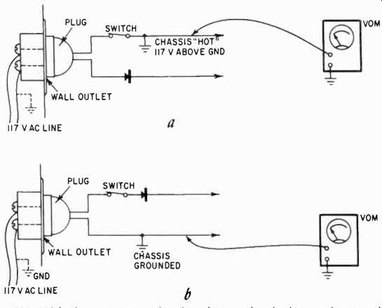
Fig. 901. With the vom set on the 150-volt ac scale, check to make sure that
the chassis isn't "hot."
The VOM in ac-dc receiver servicing
By far the majority of receivers in use in our country are the small ac-dc transformerless types. These often have a "hot" chassis, so the first use of the VOM is to make certain that you are not working on something which can be dangerous. Although 117 volts ac is not always fatal, it certainly can be.
You have removed the set from the cabinet, set it on the bench and plugged in the line plug and turned on the switch. (Replace the knobs as soon as the set is out of the cabinet but before the set is plugged in.) Now, with the VOM on its 150-volt ac scale, establish whether the chassis is "hot." (See Fig. 901.) Practically all 117-volt power lines have one side grounded; if the line plug of the receiver is in the outlet correctly, the chassis will show no voltage to ground. Ground can be a water pipe in the vicinity or, if the building meets electrical-code specifications, the outlet box itself must be grounded, and you get a ground connection there.
If the chassis shows a voltage one way to the outlet box metal and not the other, the box is properly grounded. Work on the set only with the plug inserted so that no voltage shows on the chassis.
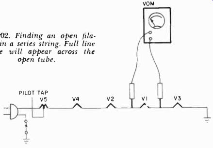
Fig. 902. Finding an open filament in a series string. Full line voltage will
appear across the open tube.
Checking series filaments
Since in these transformerless sets the tube heaters are connected in series, the entire string will refuse to light if one tube is out. This tube can be quickly located if you use the same ac scale (150-volts) on the heater pins of each tube. For octal tubes these are usually pins 2 and 7, (with a few exceptions), for miniature 7-pin tubes ordinarily 3 and 4 and 4, 5 and 9 on the 9-pin tubes. Pin No. 9 is the center tap of the heater. In series sets with 12-volt tubes, this tap would probably not be used.
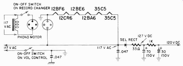
Fig. 903. Power supply setup for an ac-dc receiver.
Fig. 902 shows such a string of tubes. With the VOM you can locate the faulty tube quickly, appear across this tube. You could also take out one tube at a time and check it for heater continuity on the low ohms range of the meter.
Some series-string sets also have a resistor in series with the tube heaters. If the tubes are all OK, but do not light, look for and check this resistor.
Checking B-plus voltage
If all the tubes light yet a set does not work, check to see if there is power supply voltage. (Fig. 903.) Use the dc scales, starting with at least the 500-volt or 300-volt one. If the power supply voltage in an ac-dc set reads much less than 120 the filter capacitor is defective or the rectifier is probably not operating properly.
Coincident with low voltage when the filter capacitor is out, there is usually a clearly audible hum in the set.
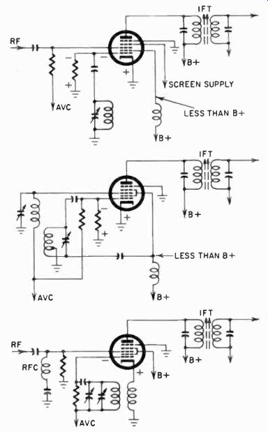
Fig. 904. Some very different-looking converter circuits. Polarity and voltage
points are indicated when checking for oscillator function using the VOM.
A quick test for filter capacitor function is to connect the meter prods to the chassis and B-plus and turn the set off. If the voltage drops to zero at once, the filter capacitor is finished and should be replaced. If the voltage is low but drops very slowly, or at least not very fast, the rectifier tube probably has lost emission.
Checking the oscillator
If the plate voltage is OK, tubes light and there is a barely audible hum in the speaker to show that the output circuit and the speaker are at least functioning, make a quick check to see if the set oscillator is working. If it is, a small positive voltage should appear at the oscillator cathode of the converter tube.
Fig. 904 shows check points on some common receiver oscillator circuits.
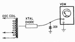
Fig. 905. A crystal diode and a VOM set on its most sensitive scale can be
used to check for oscillator operation.
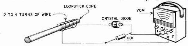
Fig. 906. Simple probe to check for oscillator function without connecting
to the circuit.
Another way to check the oscillator of a receiver quickly was explained in Section 8 under field-strength measurement. For this you need only clamp a crystal diode onto your test leads, switch the meter to its smallest current (microampere) scale and put the test-lead "probe" in the vicinity of the oscillator coil. (Fig. 905). If the oscillator is working, you will get a considerable deflection on the meter.
An oscillator probe for the VOM, easy to make and which functions at uhf as well, is shown in Fig. 906. A ferrite rod can be obtained from a loopstick antenna. (Incidentally, if you've ever wondered why these things are called loopsticks when they in no way resemble loops, it is because they exhibit the same directional characteristics as loop antennas.) The probe consists of a few turns of fairly heavy wire around the rod, a semiconductor diode and a capacitor. Brought near an oscillator this probe will show as much as 200 ua deflection on a VOM. It is sensitive enough, with a 50-ua meter, to show the presence of rf in other parts of the circuit.
Signal tracing and alignment
Most ac-dc sets can be signal-traced by touching each successive grid in the set with a metal object such as a screwdriver. If you hear an audible click in the speaker, the stage is probably working. But this is not always a reliable method. A signal generator injecting an of or rf signal would be better. This is almost certainly needed when you wish to align a set. If only the if needs to be aligned, the VOM can be a handy indicator for proper set alignment. Of the several ways to connect the VOM for this, the simplest is to attach it as an output meter across the speaker voice coil.
Then, with the volume as low as possible yet giving a definite deflection on the meter, adjust the trimmers on the if transformers for maximum output. Do not try this procedure with an FM tuner or receiver. The adjustment of the if's in these is much more critical and requires the use of the appropriate if signal, 10.7 mhz.
Another method of using the VOM for alignment is to connect it from ground or chassis to the screen grid of an if tube (or rf, if the set has one) provided the screen grid is fed through a dropping resistor. When the strength of the signal increases, the avc voltage also rises. This reduces the amount of screen current and as a result there is less of a voltage drop across the screen resistor. The voltage at the screen will rise. Use this for an indication of maximum signal.
Plate voltage at all the tubes is the next quick check, and for this you would use the high-voltage dc range of the VOM. If any plate has exactly the same voltage as the B-supply, you can be reasonably sure this tube is not functioning, for even an if trans former winding will drop the plate voltage a certain amount.
(This is shown in Fig. 907.) Tube non-operation can be caused by a variety of defects, but the most common ones are burned-out cathode resistors or open grid resistors. Check these with the set turned off and the meter on the appropriate resistance ranges.
If the VOM shows large positive voltages on the grids of any of the tubes, you can be almost sure the preceding coupling capacitor is leaking and must be replaced. This would also be indicated by excessive drop of the plate voltage across the preceding plate load resistor.
Checking avc
Proper functioning of radio receivers of the superheterodyne type also requires avc. The avc voltage is developed by the second detector or a separate diode detector usually in the same envelope.
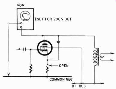
Fig. 907. An open cathode resistor means full B+ on the plate of the tube.
The same amount of voltage will appear on both sides of the load.
On a strong transmitter signal, this voltage should amount to as much as 10 to 12. This is a negative signal applied to the ground end of the grid section of rf and if transformers, to avoid over loading the stage with a strong signal. (See Fig. 908.) If this voltage is absent, the set exhibits what is known as "blasting." When you tune a station it will suddenly come in much stronger than expected, and it will be almost impossible to receive even a relatively weak broadcasting station without serious distortion. The loss of avc can result from leaky avc capacitors.
The avc method used in most receivers calls for relatively large capacitors. These store the energy provided by the signal so that, when the signal drops for a short period, it does not immediately decrease the avc voltage. If it did, the set would sound either very "flat" with all passages, loud or soft, coming out the same, or it would show a "wagging" signal, an excessive hunting of the avc trying to keep up with signal-strength variations. Both conditions can result from dried-out or open avc capacitors. If the VOM shows a rapidly varying voltage on any of the avc points, with the set tuned in on a station and left there, some of the avc capacitors are either open or too small.
Incidentally, this is one method of hooking up an S-meter, a meter which can be used to measure signal strength but is most often simply employed as a tuning indicator. Avc voltage is a sure indication of maximum tuning and, where you have "difficult-to-tune" stations, you could use your VOM this way, simply hooking it to the avc circuit to tune for maximum voltage. Use a 20,000-ohms-per-volt (minimum) VOM for this test.
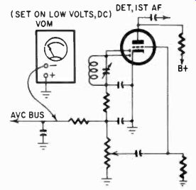
Fig. 908. Method of checking avc with a VOM.
Signal interference
Fig. 909 shows two types of wave traps. These are tuned to eliminate a particular frequency. The series circuit in Fig. 909-a does this by showing a very low impedance to the unwanted signal,
bypassing it to ground. The parallel wavetrap, working in a completely opposite manner, shows a very high impedance and does not allow much of the signal to enter into the receiver. Which ever you use depends on the situation; the series wavetrap reduces the set's sensitivity on adjacent frequencies, but the parallel wave-trap (Fig. 909-b) is less effective. These traps are used, for example, near a transmitter antenna, which might put out such a strong signal that it is heard all over the dial.
To tune the wavetrap, simply connect the VOM to an avc point, tune the receiver to the offending station and adjust the trap for minimum indication on the meter. This is sometimes the only possible procedure if the signal is strong enough to saturate the receiver audio in spite of the avc.
The appearance of a station on several points on the dial may not always be a sign you need a wavetrap. It may be, for example, lack of selectivity of the if's or a weak oscillator. There are two ways in which signal interference can take place. There is what is known as "image" frequency. Let us say you have the set tuned to 550-khz signal and the if is 450 khz. The signal from the oscillator may come in and interfere. Your reception is disturbed by the "image" of the 1450 khz station; although your tuning circuit should reject this station it enters the if circuits, creating interference there.
There is also what is called "double-spot" appearance of stations. This can happen when a signal at 1450 khz also generates an if at 450 khz (where it would create an interfering image). In double spot reception, the strong 1450 khz signal generates the second "spot" in the converter rf grid circuit by heterodyning with the oscillator signal radiated by this tube. Receivers with rf amplifiers that do not radiate do not have double spot reception. Whatever we do to prevent image reception will also cure double-spot reception. Most frequently this can he cured by proper rf and if alignment of the receiver.
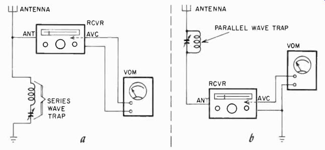
Fig. 909. Two kinds of wave-traps that can be tuned by connecting the VOM
to the avc circuit.
Locating microphonic tubes The usual method of locating a microphonic tube is to tap each in turn until a "boing" is heard in the speaker. However, some tubes are so microphonic that they sound off no matter what part of the chassis is tapped. One way of locating these tubes is to connect the VOM (set to read voltage) across the plate, screen or cathode resistor (as shown in Fig. 910) and then tap it. Micro-phonism is indicated when the meter flickers as the tube is tapped.
When testing power output tubes, keep the volume turned down to eliminate the effects of microphonics in earlier stages.
Using the VOM in FM and TV
Problems similar to those in AM receivers are encountered in FM tuners, with a few basic differences. For example, you can align an FM if strip with an AM oscillator, and connect the VOM to the discriminator or ratio detector. But in this case you must tune for a minimum signal, with the generator set for the intermediate frequency. In FM, when the signal is exactly on frequency (if) the AM will not show up, but when the signal (or, conversely, the if transformers) is off resonance, the AM will pass: the more off resonance, the more AM signal will pass. So tune for minimum signal. Of course, better alignment methods of FM if strips call for a sweep generator and oscilloscope. But a creditable job can be done with an AM test generator and the VOM if the job is done with extreme care.
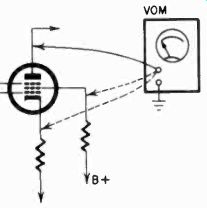
Fig. 910. Use the VOM to locate a microphonic tube.
Connect as shown and tap the tube lightly. Watch the VOM for erratic behavior of the meter pointer.
A properly functioning FM receiver does not respond to AM, but this is a function of the limiter before the second detector.
Thus, if we inject an AM carrier signal on, say, the mixer, and take the signal off for the VOM with a demodulator probe in the stage before the limiter, we can do a very accurate job of aligning these if's. The limiter if can also be aligned this way without the limiter tube in its socket, if we apply the signal to the input of the limiter transformer. Fig. 911 shows such a demodulator probe.
TV intermediate-frequency amplifiers must handle both the picture carrier, which is AM, and the sound carrier, which is FM and 4.5 me away from the AM. TV if transformers must have a very broad response. With the exception of the last one, the sound if, these can also be adjusted with an AM oscillator and the VOM connected to the video detector. Let us warn you, though, that proper TV alignment is very difficult without a sweep generator and scope.
Adjusting the linearity coil
The milliammeter function of a VOM can be used for speedy adjustment of the linearity coil (if the TV set has one). Clip the meter leads across the terminals of the fuse in the B-plus line going to the horizontal output circuit. Adjust the linearity coil for a minimum reading. That's all! Naturally, the fuse is removed when the meter is connected.
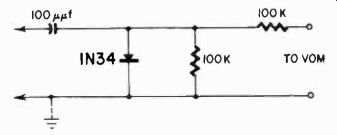
Fig. 911. A demodulator probe is needed for rf or if signals when aligning
receivers with the VOM.
Audio amplifier in a TV set
The audio section of a TV set is no more complicated than that of a broadcast receiver. In the audio section, one particularly useful measurement is the bias voltage on the cathode of the output tube. A low bias voltage will lead to distortion. This could be caused by loss of emission in the tube or by drying out of the bypass electrolytic capacitor.
When servicing the audio portion, voltage measurements will again give clues to shorted or leaking capacitors, open resistors, etc.
If a set is completely dead, the job starts from the back. Check the speaker first. Touching the voice coil with the meter prods with the meter on the low ohms range should give a clearly audible click in the speaker. From there, the next check point is the grid of the output tube, then the sound detector or the second detector. The VOM is adequate instrumentation to service all of the audio section of any receiver.
Special adapters are sold which will make service work much easier. These are tube bases (in seven-and nine-pin miniature and octal bases) with a socket on top. Between the socket and the base are short switches with exposed contacts. With these you can test the performance of a tube in its circuit, for you can measure voltages on any tube element during operation and, by opening the small switches, measure current to any element.
Sometimes when you use the VOM to measure a voltage on one of the elements in a set which has been inoperative, the set will suddenly come to life. This is a sure indication of something wrong with the return to that circuit, usually an open resistor. On the other hand, you may find that in a set which operates poorly, that connecting the VOM across two points will decrease the output or even stop the set from operating altogether.
Now this is no definite sign that something is wrong in the circuit. If you were measuring, for example, negative grid bias on a tube and using the 1.5-volt scale (which would be appropriate) you might then also short the grid to ground through such a low resistance that it would cease to operate. Similarly, an oscillator which is operating marginally may suddenly cease when you apply the test prods to measure its voltages. It may even shift frequency. Many oscillators are voltage-sensitive to a certain extent and when the voltage is further lowered by the VOM the deviation may get worse.
Portable radios
Portable radios present special problems. Servicing techniques used with these sets are slightly different from those used with home or auto radios. Several additional points must be checked to see that the finished job meets the necessary standards.
Tubes in a portable are checked the same way as ac heater tubes, and they need not be supplied with dc for the filament.
The filament is, of course, the cathode also. Alignment of portables is no different from any ac receiver.
However, when we get into combination sets usable on either ac, dc or battery, the story is different. Here special switching circuits are used to change over from the ac or dc supply to the batteries.
Fig. 912 shows the filament circuit of a typical ac-dc battery portable. This one is simple compared to some. Notice that the filaments are circuited in a particular order. This assures that the "cathode" of the output tube has, for bias, the drop across all the other filaments.
In some sets there are separate resistors from points between the filament connections to ground. When you encounter these, they are there for the same reason- to adjust the bias voltage for one of the tubes to the required value, without requiring the use of all the filament for the ground return. Thus checking filaments is complicated by these separate resistors, which might lead you to believe that a filament connection is all right. Actually, you are measuring the grounding resistor, a puzzling situation, until you remove the tubes and test them separately.
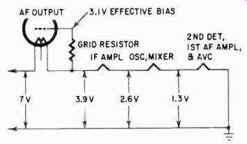
Fig. 912. Arrangement of the tube filaments in a portable receiver. The voltages
shown are approximate and are read with respect to B-minus.
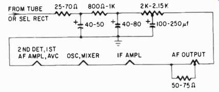
Fig. 913. Basic circuit of the power supply of a typical three-way portable.
One source of trouble in such portables is the switch which changes over from power supply to batteries. If it has poor contacts, the filament current in the tubes may be reduced. In such battery-operated tubes, the functioning of the tube is strongly dependent on filament does not have the long-time thermal storage that the ceramic-encased ac cathodes have. Any variation in filament current will immediately change the electron emission from the filament.
When the set is used on either ac or dc, the filaments are sup plied from the dc supply through a separate dropping resistor (Fig. 913). Some portables have a dual rectifier with one of the cathodes assigned to supply just the filament current for the tubes.
In others, there is a transformer for ac operation, with a bridge type dry rectifier. The latter cannot be used on dc.
In the dc position, the filaments and the B-plus are still supplied through the rectifier, and the plate voltage will be somewhat lower - 110 volts dc. If the filter capacitors are very large, they may manage to store a little extra energy and the plate voltage may be about 120, while on dc there will be only 110 volts in the first place. Thus, if your VOM indicates, when the set is on dc, that the plate and filament voltages are a little low, this is no reason to suspect immediately that something is wrong with the set.
Notice in Fig. 913 that after the dropping resistor no large filter capacitor is shown in the filament circuit. In some sets there is. If you should pull out a tube beyond this capacitor, it will allow the capacitor to charge to the full B-plus voltage and, when the tube is reinserted, the filament will promptly flare up and die.
Never pull tubes out of a battery portable with the set turned on (but not working) with the VOM on its lowest range. It may well cost you a meter. Even in the filament circuits of portables always start with the meter on the range which can accommodate the highest voltage that can occur in the set.
Remember, too, that ac-dc portables are transformerless and may have a "hot" chassis when used on the power line.
Transistor receivers
This is another class of receivers which merits special notice. Here we are dealing with oscillators which are even more touchy about proper voltages, so check for oscillator function with a probe which does not need to touch the circuit. As a matter of fact, the oscillator in transistor radios is the most troublesome section, and many fail to operate if the transistor is anything but optimum.
Alignment of a transistor receiver is different. Usually the trans formers are single-tuned, meaning there is only one slug, while the transformer secondary is not always actually at resonance. The alignment procedures of tube and transistor radios are similar though, and the VOM can be used to measure the detector output for maximum signal strength. Transistor receivers are much more critical with respect to proper voltages than tube sets, and they must be measured with greater care, considering in all cases the possible loading by the VOM.
Checking oscillation
We can seldom test directly the unwanted oscillation. The small changes in voltage on even the local oscillator do not permit direct measurements as in a tube set. Indirect methods must be used.
A wavemeter is a good way to test for oscillation. Couple it loosely to the detector input, although far more tightly than to pick up an ordinary if signal. Kill the local oscillator with a jumper or a capacitor across its tuning plates if these are hot. With no signal applied to the set any indication on the wavemeter indicates oscillation.
A handy wavemeter circuit is shown in Fig. 914. It is made up of a ferrite antenna, a tuning capacitor and a trimmer capacitor in series with a switch. The switch connects the trimmer or padder for if measurements. (The wavemeter can be used with the switch open for oscillator checking if desired.)
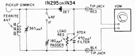
Fig.
914. The VOM can be used with this external circuit to check for unwanted oscillation
in a receiver. Set the VOM on its lowest dc voltage scale.
The VOM, set on its lowest dc range, is connected to the two tip jacks and acts as an indicator. The gimmick is simply a piece of flexible wire. In use, about three turns are wrapped around the lead or lug from the last if transformer to the detector (diode or transistor). With a printed circuit, hold the gimmick lead in parallel with that from the if transformer. The variable capacitor is tuned to the if with the switch closed. Any meter reading indicates oscillation. When the cause of the oscillation is found and eliminated, the meter will not indicate.
The avc or agc may be used if the fixed voltage is known. Appreciable departure indicates oscillation. In a transistor radio, the avc may go either positive or negative from some fixed value and can control the base, collector or emitter of the controlled stage.
Use this test with these limitations in mind.
Sometimes, the presence of oscillation can be detected by a change in voltage at the detector after checking with the schematic or a similar radio.
Batteries
The fact that batteries in transistor radios have a long life increases the possibilities for corrosion and leakage, with consequent poor contact and malfunctioning. Mercury batteries particularly, unless of the completely sealed type, show a tendency to corrode right at the battery terminal. If you remove a battery of this type from a portable or transistor set and then check it, the reading with the VOM may be misleading. By cleaning the terminals well, you may find that the battery is good after all.
Don't throw it away after a casual measurement. Replace or re charge batteries which measure less than 75% of their rated voltage under load (with clean contacts). It is possible to recharge many kinds of dry batteries at least several times.
Use your VOM to measure the voltage of recharged batteries. Don't take it for granted. A voltage which is only a little too high may damage, not only the transistors in the set, but even the electrolytic capacitors, which are usually of very large capacitance and very low voltage. Here again observe the rule of not pulling transistors with the set on; inductive or capacitive "kick" might be enough to ruin the transistor. Be especially careful how you use an ohmmeter around transistor sets. If the battery voltage of the meter is in some way added to the voltage of the set's battery, the resulting higher voltage may do more damage while you are trying to discover what is wrong.
On the other hand, some of the large capacitors in the set may have enough "bounce," even when you think they are discharged, to give the meter an unmerciful kick, particularly on the ohms ranges. In an electrolytic capacitor, the nature of the electrolyte is such that it may actually recover some charge in the capacitor even after it has been thoroughly shorted when you discharge it.
The larger the capacitor, the more likely is this to happen. Al ways check first with the voltage ranges to see that there are no stray capacitor charges sitting in the set, before going to work with the ohmmeter section.
In transistor sets, be especially certain of your battery polarity. If the battery plug is not polarized, wrongly inserted batteries can damage transistors and the low-voltage electrolytic capacitors. The VOM can be used to establish polarity, if you aren't sure of it. Most sets have the battery position clearly marked, but a few do not.
Testing power transistors
One of the quickest checks for abnormal operation of power transistors is to test for collector voltage. If this voltage is low and all other conditions seem normal, the transistor should be tested for low gain and internal leakage. This is done with the ohmmeter section of the VOM. Disconnect the base and emitter leads from their circuit connections, leaving the transistor bolted firmly to its heat sink. It might be a good idea to check for shorts between the transistor case and the chassis after disconnecting the output transformer's primary.
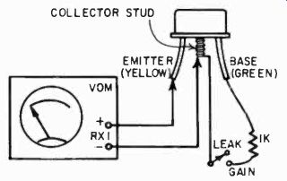
Fig. 915. Setup for checking power transistors with the VOM.
Check the ohmmeter's polarity. Most service type instruments have a positive lead to the red or ohms jack, but some differ. Set the instrument on R x 1, and leave it there! On this scale, only a small battery is used. Some instruments use as much as 22.5 volts on higher ranges, and this can harm transistors.
Connect the ohmmeter's negative lead to the collector stud and the positive lead to the emitter. A zero ohms reading, dead short, indicates a shorted transistor. If a fairly high reading is shown, the transistor is probably OK. A low ohm reading indicates a leaky transistor or the possibility that the transistor is still too hot. Wait a few minutes and recheck.
For a final test, connect a 1,000-ohm resistor between the base and the collector stud (Fig. 915). The meter should now show a decided decrease in resistance, and should read less than 50 ohms.
If not, the ohmmeter polarity may be wrong- recheck. If the reading is more than 50 ohms with the 1,000-ohm resistor connected, either the base lead is open or the transistor has very low gain and should he replaced.
The VOM in hi-fi
One of the first jobs for the VOM in hi-fi that comes to mind is the phasing of speakers. Whether you use stereo or monophonic reproduction, if you use more than one speaker, they must be properly phased or the sound will be acoustically distorted.
Phasing speakers with the VOM is very simple. Using the low ohms range, the battery in the VOM will cause the cone of the speaker to deflect either one way or the other if you apply the test prods to the voice-coil connections. As you do this, note whether the cone moves in or out, and mark the terminal which was connected to the red test prod. When you check the second speaker, switch prods until the speaker cone behaves in the same way. Again mark the connection of the red test prod. When the speakers are used together, on the same set, you must then ob serve your polarity marks. This is true whether the speakers are in series, parallel or connected through a crossover network (Fig. 916).
With some tweeters (for example, electrostatic units) this polarity check is neither possible nor needed. Since like charges repel, when a voltage swing from the output tube goes up (more positive), the diaphragm of the speaker will move in because this puts a negative charge on the grounded plate. Thus, if you use an electrostatic speaker in your system, it must be phased so that the cone speakers will also move in when the signal has a positive swing.
Some diaphragm tweeters are hard to check because the diaphragm moves so very little. However, if you remove the horn and stretch a piece of a toy balloon over the narrow horn mouth, the motion of the diaphragm can be observed. Do not stretch it too tightly, but make sure that the balloon rubber is airtight around the mouth.
The proper phasing of speakers is most important in stereo, since the sound in both channels is the same set of sound waves, moving in the same direction. Therefore, we want to reproduce it that way also.
Stereo is recorded through identical amplifiers, and to reproduce it with full stereo effect it should be amplified through systems which are as nearly the same as possible, if not in actual physical similarity, then at least in a functional sense. When the equipment is built in duplicate for both channels, there is no serious problem. You simply have to observe the proper phasing of the speakers and the setting of the controls (they must be the same) . But if you use two very dissimilar channels, such as an FM and an AM radio, this setup has several problems which the VOM can help you solve for maximum stereo benefit. First of all, since you have different amplifiers, you can adjust the speaker output to approximately the same level with the output function of the VOM. Connect the VOM to each of the speaker voice-coil connections in turn, and set for approximately the same output level. If the speakers differ very much in size, or even if they are the same size, this does not actually guarantee that the acoustical
output will be the same, since there is a lot of difference in speaker efficiency. But at least it will be an approach, and you can make allowances for various speaker sizes. If you use one of the sensitive transistor amplifiers for your VOM which were described earlier, then you can connect a microphone to the meter through a diode (you'll be measuring ac), and, at the same distance from the speakers, compare the voltages generated by the microphone. Adjusting the controls for the same average deflection on the meter will assure you of identical acoustical output of the two dissimilar channels.
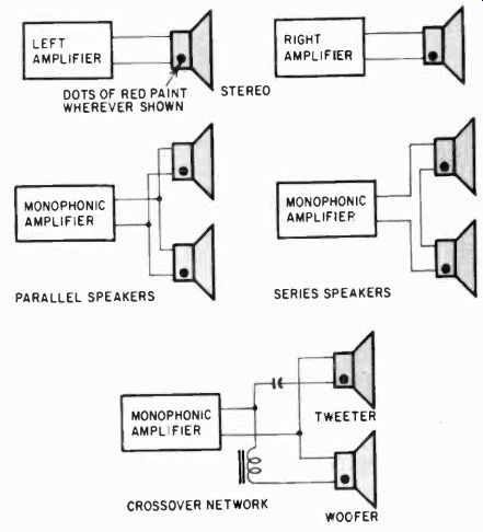
Fig. 916. No matter what speaker arrangement the audio or hi-fl system uses,
always observe speaker polarity--as checked by the VOM.
Phasing of such a set of speakers in different cabinets is also something of a problem, but one which is fortunately simple to solve with a little gimmick, a strip of paper. Cut a strip of paper about 1 to 2 inches wide, and hang it in front of a speaker, about 1/8 inch away from the grille. Watch the strip move on heavy passages, when you turn up the volume. Now face the speaker with the other one, about 1/4 inch apart, and turn up the pro gram volume to about the same level (see Figs. 917-a,-b). If your speakers are phased properly, the strip will hang almost perfectly still; if the speakers are out of phase, the strip will move wildly. Speaker phase can be reversed simply by transposing the voice-coil connections.
It is not sufficient in this case to disconnect one side of the voice coil and observe the cone motion. If you do this, and mark voice-coil polarity, you have to do something more. Reconnect the voice coils to their transformers, and connect one side of the voice coils together or, if they are grounded, connect the chassis of the sets together. (Careful! In ac-dc sets, make sure the chassis are both "cold.") If the output transformers as well as the voice coils are of the same polarity (phase), and you connect the output section of your VOM between two equally marked voice-coil connections on the two sets (Fig. 917-c), then you should measure no, or very little, voltage if the sets each produce about the same voltage across the voice coil. With opposite polarity, there would be about twice the voltage of one. But this procedure is useless unless you have first marked your voice coils for polarity.
Checking push-pull balance
Output stages in push-pull amplifiers must be carefully balanced, and many amplifiers have a balancing potentiometer in the grid circuit which can be used to make the final balance.
Some of these also have jacks in the cathode circuits, so that the dc flowing through each half of the output transformer primary can be adjusted to exactly the same value. This prevents dc magnetization of the core which can cause distortion. If no jacks are available, you can use the volts ranges of the VOM instead of the current ranges, and check the voltages on the grids or cathodes.
If it is impossible to achieve balance, it may be that small differences in tube characteristics and components are adding up. so try swapping output tubes to see if balance can be obtained that way. If not, you'll be better off starting with a new set of balanced tubes.
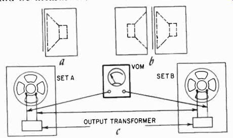
Fig. 917. Method of checking speaker phasing
Lack of balance in the output stage might be a result of lack of balance earlier- in the phase splitter, for example- and a quick check with the VOM across the plate and cathode load resistors of the phase splitter will tell you about this.
Tape recorders
Interesting problems arise in servicing tape recorders. Tape recorders have a bias oscillator, which may be operating anywhere from 20 to 100 khz depending on the recorder. Inexpensive ones use a bias from 20 to 30 khz. These oscillators can be checked with the type of probe using a diode, but they are usually pretty husky oscillators and an ac voltage across the bias winding in the tape head should be measurable. The bias oscillator is on only when the unit is in the record position. It usually has several safety interlocks which prevent it from operating, and incidentally erasing the tape, when it is not desired.
In some recorders the lockout takes a different form. The bias oscillator tube finds double use in recording, as an oscillator; in playback, as an output amplifier. These circuits have complicated switching, and experience has shown that these switches can be a major source of trouble. Thus, a careful continuity check with the low ohms range of the VOM may often lead you immediately to the source of trouble.
With a tube removed (and the amplifier off, with power-supply capacitors discharged) a check of the resistances from the tube pins to ground should tell you a great deal. Grid circuits should have the appropriate resistance to ground and, if the meter kicks to near zero, then rapidly rises to, say, a 50,000-ohm resistance, suspect the coupling capacitor ahead of the tube position being checked. On the other hand, this is the correct behavior for the supply to the screen grid, say, in an output circuit, since the screen usually has little resistance in its supply.
If the plate or screen shows less than 5,000 ohms to ground, you have a short on your hands. If the resistance to ground shows high enough, but there isn't the first low kick and then the gradual rise of resistance, your electrolytics may be done for.
A cathode bypass capacitor is not that easily tested. This check is best done with the amplifier on and a signal going through.
If the cathode voltage varies with the signal, the capacitor is at least insufficient, if not inoperative. Use the dc voltage ranges of the VOM for this test.
Speaker matching
One recurring problem in audio, whether it be hi-fi or public address systems, is matching the speaker to the output transformer.
There is always a stepped arrangement; that is, you have a choice of maybe 4-, 8-, 12-, 16-, and 20-ohm taps on the transformer, not a continuous change. Thus, if you can determine approximately the best tap, this is the best you can do in matching to that particular amplifier. This can be done fairly directly. When the transformer and speaker are matched perfectly, there is the maximum transfer of energy; in other words, voltage times current is the greatest. If you arrange to measure both the voltage and current across the speaker (Fig. 918), and multiply each current measurement with its voltage measurement, the combination which gives the highest product is the best match.
To do this, you must provide a steady signal to the amplifier, turn up its volume to maximum and take your various measurements, being sure to turn down the amplifier when changing taps.
The small 0.5-ohm resistor inserted in the circuit is removed later, and it also causes some mismatch, but much less than the difference between taps on the transformer. If the amplifier produces, say, 20 watts, this means, in a series circuit of 8 ohms in the power transformer and 8 ohms in the speaker, the rms current would be 1.25 amperes. This through a 0.5-ohm resistor would create 0.6 volt ac, enough to read clearly on a 2.5- or 3-volt scale.
The voltage would increase, as the impedance tap is higher, and the current would decrease. But in the power measurement, the current is squared (I2R) so neither the highest current nor the highest voltage is the proper match; only that point at which the product of the two is highest. With five or six taps on the trans former, it won't take long to calculate which produces the best power output. in the speaker.
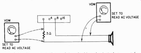
Fig. 918. The VOM can be used for checking the impedance match between the
speaker and the output transformer of the amplifier.
Many "tricks" of the trade really require only common sense and some knowledge of what circuit elements will do. Thus, we must remember that when we get the VOM ohms ranges across a large capacitor, electrolytic or paper, it will gradually charge to the battery voltage in the VOM. When we check the resistance of small capacitors (not electrolytics), their resistance should measure in the hundreds of megohms to be in good condition: but even if it does, that is no guarantee that the capacitor will not break down under a higher operating voltage. Here is one case where the VOM can provide a false picture. Electrolytics with rated working voltage applied should pass about 1 to 1.5 ma per microfarad maximum. Anything more than that indicates deterioration and anything less than 0.5 ma should lead you to suspect a dried out capacitor. It is good practice, even before turning on a set or an amplifier which is in for repair, to make a complete resistance check, particularly of the power supply components. This may reveal a short which could soon damage other parts. Voltage checks of power supplies with the equipment on are the next logical step in investigating inoperative equipment.
Printed-circuit problems
Printed circuits have been finding their way into audio equipment, transistor radios and TV receivers on a rather large scale and bringing with them certain problems characteristic only of printed circuits. When a circuit board is flexed, as it may be when removing tubes from it or replacing them, the possibility always exists of cracking the circuit lines. These cracks may be minute, invisible to the naked eye, but sufficient to interrupt the circuit or, worse, to interrupt it intermittently. Such hair-line breaks can be found rapidly with the low ohms range of the VOM, since the normal resistance of a circuit conductor is usually written several places to the right of the decimal point. Any resistance over 0.1 ohm in a circuit line indicates that the line is either starting to develop a fine crack, or is in some other way corroding or deteriorating, and careful inspection of such a line with a magnifier is necessary.
Another bugaboo of printed circuits is the eyelets sometimes used for attaching components or to connect circuit lines on two sides of a board. Many of the processes used on circuit boards involve acids and other strong chemicals which are basically corrosive. If just a microscopic bit of this kind of chemical has been left on the copper before the eyelets are inserted, trouble may develop, even though to the eye the connection appears properly soldered. Again, ohmmeter checks may indicate this but, to be really certain, use the shunt-ohmmeter system described earlier for measuring very low resistances.
The third kind of problem showing up in printed wiring is insulation trouble. If any moisture condenses on a printed-wiring board, there is the possibility of electrolysis which may deposit conductive salts on the surface of the board's insulation and eventually cause breakdown. If two circuit lines are connected through a low resistance, since current will always take the path of least resistance. But if two such lines are not in any way connected, electrolysis may have serious consequences. The best medicine here is preventive. Check the board with the high-resistance range of the ohmmeter. If your meter goes up to 100 megohms, for example, and you can get some deflection when measuring lines which are supposed to be isolated, trouble can develop. Sometimes it can be prevented by a thorough cleaning of the board. Do not use any solvent on printed-wiring boards. Solvents leave deposits which are as bad as dirt but in a different way. A dry clean rag should give all the cleaning needed.
After cleaning, measure the insulation again. Use, if necessary, one of the methods described earlier for measuring very high resistance.
If circuit lines are broken, the best remedy is to solder (with a low-heat iron) a short piece of wire across the break. If circuit lines are beginning to show low isolation resistance, the board can often be saved by taking a very sharp little knife and cutting a shallow groove between the lines. This disturbs the glazed surface, and it should be restored with a lacquer or special silicone coating.
Transmitter servicing
The VOM is as handy in transmitter servicing as in receiver work, and has a few additional applications in it. Fig. 919 shows a partial transmitter schematic, mostly the final amplifier and the oscillator-driver. The tuning of the transmitter can be done with the current ranges of the VOM. Notice that, in the power amplifier cathode, the manufacturer has installed a jack and it is here you can measure the total amplifier cathode current with the current ranges of the VOM. In tuning an amplifier, assuming that the oscillator is working, crystal controlled and on the proper frequency, the current in the power amplifier, without the antenna connected, is adjusted for a minimum, since at that point the tuned plate is at resonance and has its greatest impedance.
The final tuning of the transmitter includes the tuning of the antenna. This requires an rf ammeter, and usually the measurement is made with a thermocouple type. But again we can put the VOM to work if we use a noninductive resistance, small capacitor and a diode to convert antenna current into a small dc voltage. When this procedure is used, remember that the antenna will be tuned a trifle shorter than it should be, but the difference will not be significant.
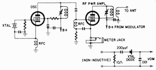
Fig. 919. Partial schematic of a typical transmitter. Adjustment of the final
stage can be done with the VOM connected to the meter jack.
A quick check of transmitter modulation can be made using the VOM. With the transmitter tuned and on, but unmodulated, measure the current in the antenna. Now with a steady note supplied to the modulator microphone, the meter reading should increase 22 1/2% for exactly 100% modulation. For less increase you are under-modulating and not taking advantage of the transmitter's capabilities; with more than 22 1/2% change in reading, you are over-modulating and causing distortion in the signal.
In transmitter work, the VOM really comes into its own as a field strength meter and can serve, for example, as a monitor. A simple tuned circuit, diode and VOM wavemeter, set up in the vicinity of the transmitter, will serve to indicate if the transmitter is radiating. Moreover, it will give a check on frequency deviation, since there is nothing in such a simple circuit which can change the reading except if the frequency of the transmitter changes and the circuit is no longer in resonance with the transmitter. Modulation of the transmitter will be evidenced by an increased reading on the field-strength meter.
The VOM as a field-strength meter can also be used to determine the radiation pattern of the antenna. Circling the antenna, note the meter reading at regular intervals, say every 10 feet. This need not be a calibrated reading, only a relative one. When the notations of such readings are plotted, and the points of equal reading connected by curved lines, the pattern of the antenna will emerge.
Servicing the modulator of a transmitter is so similar to servicing an audio amplifier that no additional comment is necessary. However, remember when working on transmitters that the FCC frowns on tests while radiating and that most of the work on the transmitter must be done without an antenna or with a dummy.
The dummy antenna is simply a series circuit of a non-inductive 10-ohm resistor and a 200 uuf capacitor. Remember too, that the voltages in the transmitter are likely to be higher than in a receiver, so always protect your meter by starting your readings on the highest ranges.
In this section we have been able to indicate some service applications of the VOM. Others will no doubt occur to you as the need arises, and as your familiarity with the instrument grows.
And some of them are already so common and familiar that they need not be used as illustrations. In the next and last section we will discuss the use of the VOM in somewhat less familiar ways and situations, but nevertheless generally useful ones, with some further hints on how to care for your instrument.
Also see: Link | --Guide to VOMs and VTVMs