The VOM can be used (since it contains a suitable meter) as the basic indicator in many instruments. It is, of course, possible to use it in almost any instrument which needs a meter. But this would probably tie up the VOM at just about the same time you needed it for some other application.
In the shop, though, and in the ham shack, many instruments highly essential to operation or service work are used only once in a while, comparatively speaking. This does not mean that they are nonessential but, if you can avoid tying up money in such instruments, they are all the more worth while to keep around for when you need them.
There are also times when you may need greater sensitivity or perhaps greater input resistance than is possible with the VOM, yet these instances may not be sufficiently numerous to warrant the purchase of a vacuum-tube voltmeter. In this section we will show instruments which are, on the average, used infrequently, yet are relatively important and certainly handy to have around.
We will use only the VOM for the basic meter, showing all that it can do in this sense.
The VOM as a null detector
A mull detector locates a null, a point of zero deflection, a point of no voltage and no current through the meter. This type of indication has certain advantages. It tells us, for example, when two values are equal. Its most common use is in bridge circuits. In the last two sections you learned how to extend meter ranges to measure values not normally included in the scales. In one way this was done with simple accessories; in another we made the instrument more sensitive by reading a difference voltage only.
For resistance, there is no such simple way; we must use some kind of a bridge circuit.
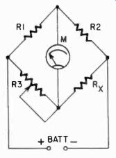
Flip 801. Simple Wheatstone bridge circuit using the VOM as a null detector.
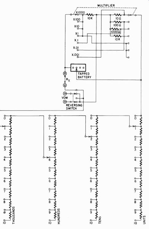
Fig. 802. Complete circuit of a Wheatstone bridge which can use the VOM as
a null detector. The unknown resistor is placed across the terminals marked
R,. The reversing switch is needed since the meter in the VOM is not a zero
center type. If, in using this instrument, the meter pointer starts to move
to the left, put the reversing switch in the opposite position. The large group
of tapped resistors in the lower part of the circuit are equivalent to R3 in
Fig. 801. When the bridge is balanced, the meter pointer should read zero,
since, with a state of balance, no current flows through the meter. For a final
adjustment, the range switch on the VOM should be set to read the smallest
amount of current.
The most famous of bridge circuits is the familiar Wheatstone bridge (Fig. 801). Four resistors (R1, R2, R3 and R.) are shown circuit-wise in the form of a square, with a battery attached to two corners and a meter, originally a galvanometer connected to the other two. Looking at the top leg, you can see that the corner at which the meter attaches has a voltage which is the result of the divider R1, R2 across the battery. If we make the ratio of R3 and the unknown R. the same as the ratio of R1 and R2, then the voltage at the other meter terminal will be the same portion of the battery voltage, and the meter will indicate nothing, a null.
We have then the equation:
If we make R3 adjustable and choose R1 and R2 in such a way that their ratio is approximately the same as we expect the ratio of the other two to be, then we can very exactly adjust R3 to the precise ratio. If R3 is a calibrated potentiometer having a scale, or if it consists of a series of precision resistors which we can progressively switch, then we can adjust it and read the value of R closely. If we make the ratio of R1/R2 large, then we must also make R3 large compared to R..
Since we are always limited in our adjustment to finite decrements (meaning we can never adjust smoothly, always in small steps) even on the best potentiometer, the larger R3 is, the more precisely we can adjust it, since we can take smaller steps, comparatively speaking. Our approach is similar to the one we used for increasing the sensitivity: we develop the situation where a small difference gives us a great amount of deflection on the meter.
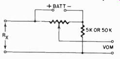
Fig. 803. simpler form of home-constructed Wheatstone bridge for use with
the VOM. The potentiometer, which can be a 100,000-ohm wire wound unit, represents
R1 and R2 as in Fig. 801. The fixed resistor, 5,000 or 50,000 ohms is R3.
Usually a Wheatstone bridge is a complete instrument, enclosed in a box, and RI and R2 are made up so that their ratio is expressed in multiples of 10^- 1, 10, 100, 1,000, etc. This limits the number of resistors needed for R1 and R2 and makes the switching simple. R3 will then be a series of steps representing units, 10's, 100's, etc., all marked in such a way that we can read at once the value of R. when the bridge is in balance.
Fig. 802 shows a complete Wheatstone-bridge circuit. The meter will deflect one way or the other, depending on whether R3 is too large or too small for the proper ratio with R.. Therefore, if you plan on using the VOM for the meter, it should have a reversing switch. If not, such a switch must be provided in the bridge box.
Normally a bridge galvanometer is also provided with shunts, so that when the bridge is badly out of balance the meter will not be damaged. In a VOM, shunts are already present, of course, in the current ranges. However, if you shunt the 10-ampere circuit across the bridge, you make it a very insensitive device. So, when we use the VOM for a bridge null indicator, the best way to start is on the voltage range, which is capable of measuring the bridge battery voltage. This is the very maximum indication which can be expected. When the bridge is near balance, as when the meter on that range shows no deflection to speak of, you can then switch to the next lower voltage range, and after that to the low current ranges, where the VOM is in its most sensitive position. Thus you can balance the bridge with almost as much sensitivity by using a 20,000-ohm-per-volt VOM as by using an expensive galvanometer.
If your measurement problems don't warrant buying a complete bridge, yet you must frequently know accurately the value of resistors within a limited range, then you can make a simplified version of the bridge with one accurately calibrated potentiometer and a few known precision resistors (Fig. 803). The calibrated potentiometer is a 100,000-ohm wirewound unit, which is used for R1 and R2. For R3 you will need precision resistors of 50,000 and 5,000 ohms. Then you can read accurately between 500 and 500,000 ohms. But the accuracy will depend to a great extent on how large, clear and accurate the scale for the potentiometer is. It can be marked directly in values for Rx.
The Wheatstone bridge is unsuitable for very high and for very low resistances. With an ohmmeter or with the current ranges of the VOM you can measure very high resistances with an accuracy which is usually sufficient for practical purposes. For very low resistances, a Kelvin double bridge is used. But this must be specially constructed. With careful work the shunt method described earlier usually provides enough accuracy (with sufficient care) to keep the circuit from loading the battery too much.
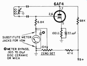
Fig. 804. The yam can be used as a substitute for the meter in a grid-dip
oscillator. The VOM will then act as a null indicator. Use the lowest possible
current range on the meter that will give the maximum swing in toward the null.
The meter is most sensitive on the low current ranges.
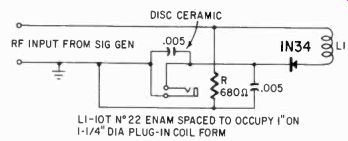
Fig. 805. Schematic of the grid-dip adapter to be used with the VOM and a
signal generator. A jack is used to permit. easy removal of the VOM when it
is to be used for other work. Use the minimum current range that will give
a suitable indication. This will be a null-type of operation.
Null detection in a grid-dip oscillator
The VOM can also be used for a grid-dip oscillator or grid-dip oscillator adapter. A small handy instrument, the grid-dip oscillator consists of an oscillator tunable by a variable capacitor. The oscillator is made to cover many bands by means of plug-in coils.
The oscillator has a meter in its grid circuit. When the coil is brought near a tuned circuit, and adjusted to resonate with this circuit, there will be a sudden dip in grid current, due to the absorption of the energy by the tuned circuit. Thus it supplies a usable minimum or null indication.
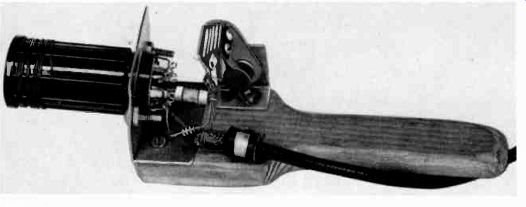
Fig. 806. Photo of the grid-dip adapter whose circuit appears in Fig. 805.
The signal generator is connected to the adapter through a small length of
coaxial cable. The long handle and the metal base plate of the coil help eliminate
hand-capacitance effects.
Fig. 804 shows the circuit of a grid-dip oscillator. A VOM with the proper
range, in this case 500 ua, can be substituted for the built-in meter. Many
amateurs build their grid-dip oscillators to use their VOM's. A jack must be
supplied for connecting the meter.
You can even go a step further and, instead of using the specially built oscillator, use your rf signal generator and the VOM for indication. This surely is the minimum expenditure for a grid-dip instrument. Fig. 805 is the schematic for the instrument in Fig. 806. The signal generator supplies the rf, through the small ceramic capacitor and diode. The diode rectifies the current for measurement by the dc ranges of the VOM. In practice, the coil is loosely coupled to the tuned circuit and, when resonance is obtained, a drop in current will be noted due to the loading of the signal generator. If the generator does not have enough output, the dip will be somewhat indistinct. It may be possible to increase your rf signal generator's output by putting a jumper across the series output resistor found in many generators. In some commercial models this series resistor is built into the output cable.
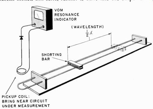
Fig. 807. The VOM can be used with a pair of Lecher wires as a null indicator.
A point-contact silicon diode can be used as the rectifier. Types such as 1N21B, 1N23A, 1N23B or 1N82 are suitable. The pickup coil can be an air-wound unit of one or two turns.
In any case, the dip adapter must be connected by coaxial cable to the generator, particularly for use at the higher frequencies.
Lecher wire null detector
Another null-detection application of the VOM can be its use with Lecher wires (Fig. 807). These are a set of parallel wires used to check high-frequency oscillators. The parallel wires are shorted by a bar which can be moved the length of the wires. The transmission line formed by the parallel wires will (when energized by an oscillator through the pickup coil) have standing waves on its length.
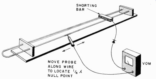
Fig. 808. Method of using the vom to locate a quarter-wavelength null point
on the Lecher wire system. The shorting bar must be at the resonance point.
Using a resonance indicator, in essence similar to the grid-dip oscillator, you can find two points for the bar at which the Lecher wires will absorb a large amount of energy. These points are separated exactly a half-wavelength of the measured radiation and thus, by carefully measuring the distance between them and dividing this figure (in meters) into 150, you get an answer in megacycles.
The VOM is connected through a crystal diode to a simple coil of one or two turns, which should suffice to give almost full-scale deflection on the 50-ua scale, even from a receiver oscillator.
Another way to use the VOM in this setup is particularly handy if the Lecher wires are too short to show two dip points for a particular frequency. Since standing waves have points of high and low voltage, it should be possible to find also a point of low voltage a quarter-wavelength away from a high-voltage one. The procedure is illustrated in Fig. 808.
Using the shorting bar, one dip point is located, indicating resonance at that point. Now the VOM leads are connected as shown, with the diode in one leg. When the prod is moved along one of the wires away from the shorting bar, a point will be en countered where the reading of the meter will suddenly drop to virtually nothing. This is a null point, a quarter-wavelength from the shorting bar, and once again the exact frequency can be determined.
Because the ac ranges of the meter are not usually sufficiently responsive to uhf, we use a crystal diode and the dc (current) ranges of the meter. A small capacitor in parallel with the meter will increase the reading somewhat, but will also make the dip show up a little more slowly, due to stored energy in the capacitor.
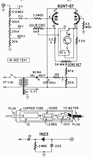
Fig. 809. Vacuum-tube voltmeter adapter which can use the VOM and the probe
which is needed with it.
A 20,000-ohms-per-volt instrument is almost certainly needed for this kind of work, although a 1-ma movement can sometimes be used if the power of the generator is great enough. Transmitters usually emit enough for the 1-ma meter or handy-tester type of instrument.
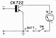
Fig. 810. Elementary transistor current amplifier.
Amplification for the VOM
The VOM can be made more sensitive by using some form of amplification. There are many possibilities in this area. We can use voltage amplification and thus make a vtvm out of the VOM, or we can use transistor current amplification and make the instrument a very sensitive current meter. (See Section 3.) Fig. 809 is a simple example of such a vtvm circuit. The schematic is shown for a 500-ua movement, but much greater sensitivity can be had by using a 50-ua unit. The meter as shown has ranges of 1.5, 15, 60 and 600 volts. With a 50-ua meter, after recalibration, these would become 0.15, 1.5, 6 and 60 volts, and for higher voltages the VOM should be switched to a higher range. However, remember that the calibration may have to be individually adjusted for each range, since the difference in resistance of the ranges would change the operating point of the two triode sections.
As shown, the vtvm is capable of measuring only dc voltages, since the meter movement would not respond to ac appearing at the cathodes of the tube. However, an ac probe can be built with the instrument (Fig. 809).
The meter in Fig. 809 must be specially calibrated, since there will be a noticeable difference between ac and dc readings. However, a separate set of multipliers could be designed for ac so that the same scales of the meter can be used without recalibration, although the lower portion of the scale in ac measurements is not likely to be linear.
A circuit could be constructed similar to that shown in Fig. 809 which could make use of the ac ranges of the VOM, but there would be a considerable sacrifice in sensitivity. With the proper calibrating and multiplying resistors, you may be able to achieve conformity of the ac voltage measurements with the ac scales on your VOM which would make the entire setup more accurate and convenient. This would have to be worked out for your particular VOM, and it depends on the ac scales shown on it.
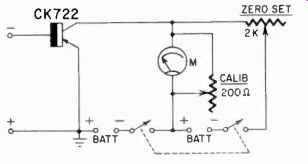
Fig. 811. Transistor amplifier for the VOM supplied with a zero setting circuit
and a calibrator to match one of the VOM scales.
The VOM is used in place of the position occupied by the meter.
Transistor current amplification
The transistor is basically a current amplifier and is well suited for some simple current amplifiers which can be constructed to give your VOM much more sensitivity. A step beyond this would be taking advantage of current amplification to make a sensitive voltmeter which uses the VOM as its basic instrument. Fig. 810 shows the simplest form of current amplifier which can be built.
If you use a 1-ma movement, you can have a current meter which is, in effect, equivalent to a 10-ua meter, very sensitive in deed. Take advantage of its sensitivity by making it into a volt meter with 100,000-ohms-per-volt resistance. Fig. 811 illustrates the circuit diagram, but in place of the 1-ma meter shown you can use your VOM.
With a 20,000-ohms-per-volt meter, you could build an even more sensitive voltmeter, but there is a practical limit to what you may need. There is also one other problem . . . the element of instability: the effect of temperature on the transistors. Thus, by merely holding one of them between thumb and forefinger, you can warm it enough to get almost full-scale deflection. There fore, transistors in this kind of a circuit must be mounted so that they are either well ventilated and assume room temperature, or well insulated so that they are not much affected by room-tempera ture changes. In either case, it is necessary to check the ZERO SET each time you take a measurement. Also, do not leave this meter connected to the source for any great length of time. for the current flowing through the transistors may, in time, warm them enough to change the reading. It is nice to have such a sensitive meter, but the penalty is the extra care it needs.
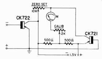
Fig. 812. High gain transistor amplifier for the VOM. This circuit has zero
set and calibration controls. The disadvantage of this circuit is that it is
susceptible to temperature changes.
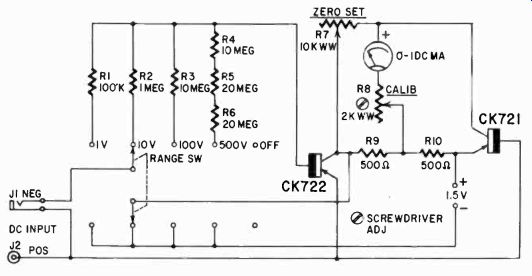
Fig. 813. Sensitive voltmeter using transistors which can be designed for
the VOM as its basic meter. The sensitivity of this instrument becomes so great
that it can be used as a field-strength meter, when the VOM is a 20,0000-ohms-per-volt
type.
Fig. 814. Balanced transistor amplifier for the VOM does not have the temperature problem encountered in single-ended amplifiers. This assumes that both transistors are reasonably well matched. This circuit is for use with a VOM having a sensitivity of 20,000 ohms per volt.
The circuit of Fig. 811 has the obvious disadvantage that the meter will always indicate some current. This problem has been solved in the circuit shown in Fig. 812. A calibrating potentiometer has also been included so that the deflection of the meter can be standardized for one of the meter scales.
The maximum gain obtainable with this kind of current amplifier is about 20, depending somewhat on the transistor used. Some very good transistors may give a gain as high as 50. Whatever the gain for the one you build, you will probably "calibrate" the circuit down to an even multiplication of some VOM scale, so probably you will be using the 10, 20, 25 or 30 gain figure. Consider that this amplifier, which can be built very compactly, can turn the 50-ua scale of your VOM into a 2- or 5- or even a 1-ua scale, or, if you have a less sensitive instrument with a 1-ma meter, it can make this instrument as sensitive for current measurement as a 20,000-ohms-per-volt unit, at very little expense.
You can carry this process a step further, and use two transistors to get really high current amplification, as in the circuit shown in Fig. 813. The transistors are cascaded to produce a gain of about 100 or more, and thus you can obtain a sensitivity of 0.5-ua full scale for a VOM with a 50-ua scale. This is a sensitivity well beyond that ordinarily needed in service work, but might be useful for changing the VOM into a sensitive field-strength meter.
A circuit which uses a different approach is that shown in Fig. 814. A very sensitive arrangement, it does not have one of the major disadvantages of the previous circuit-the temperature effect. If the transistors are reasonably matched (and we can assume that they will reach the same temperature rise) the ac curacy of the instrument should be affected little or not at all by temperature changes. As shown here the circuit is designed for a 50-ua scale. The original circuit was designed for a 20-ua meter, and for this it would of course show much more sensitivity.
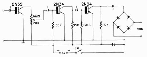
Fig. 815. Sensitive ac amplifier for the VOM to be used as a null detector
in ac bridge circuits, or to increase the ac sensitivity of the instrument.
Similarly we can amplify the signal to make a more sensitive null detector out of the VOM. With a 50-ua scale, the circuit of Fig. 815 can be used. Because it shows rectification before energizing the meter, this will be your clue to the fact that this null detector is designed for ac only. The Wheatstone bridge discussed earlier can be used with ac as well as dc; the reason that it is usually used with dc is the fact that originally the circuit was designed for sensitive dc galvanometers.
There are a number of bridge type circuits using ac which are useful for measuring capacitance, inductance and resistance values. We studied the null detector here because it is the natural companion to the very sensitive dc voltmeters using transistor current amplification.
Field-strength measurement
A popular use for the VOM, field strength measurement, can be approached in several ways. If you are close to a source of radiation, it may be unnecessary to tune the field-strength measuring circuit carefully. You may be able to obtain comparative readings with such a simple arrangement as Fig. 816. Here the 1N21 diode is shunted across the meter leads, and the meter turned to its lowest-possibly the 50-ua scale. With a grid-dip oscillator several feet from the meter, this should provide almost full-scale deflection.
This circuit is unsuitable for uhf, since the test leads of the meter are too long and the circuit will probably be resonant to a much lower frequency. In this case, special short meter leads can be made to reduce the wavelength of the meter circuit. however, in measuring uhf field strength, you will probably be more interested in picking up the radiation from a specific source, and tuning should be used.
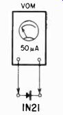
Fig. 816. An extremely simple type of field-strength meter.
This is suitable only in areas having high signal strength.
For this a somewhat more elaborate circuit is needed. A typical tuned field-strength meter is shown in Fig. 817. Notice its similarity to a grid-dip-oscillator tuned circuit. Many gdo's are indeed used as field-strength meters with the power turned off, but the meter circuit is not always sensitive enough to indicate low-level radiation.
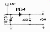
Fig. 817. Field-strength meter with the VOM used as the indicator.
To make the field-strength meter more sensitive, we can employ two methods. Which you select depends on the sensitivity desired.
One method is to make the antenna longer or more efficient, but this is not always a good procedure if you are dealing with high-frequency radiation. The other is to make the meter circuit much more sensitive, and for this you can use any of the transistor amplifiers already discussed. Simply interpose the transistor amplifier between the tuned circuit (with rectifier) and the meter.
For the uses to which field-strength meters are generally put by the amateur or experimenter, it will not be necessary to calibrate the meter accurately. Only in the determination of interference strength, as carried out by the FCC, would we need a calibrated meter. The meter would then be calibrated in microvolts per meter; i.e., in microvolts generated on an antenna exactly 1 meter long. However, most amateurs and service technicians use field-strength meters for such purposes as orienting and positioning antennas, detecting antenna radiation patterns, and indicating whether an oscillator is operating, and all of these are relative measurements only.
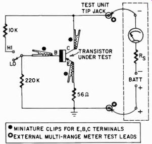
Fig. 818. Simple transistor checker using the VOM for a battery as well as
a meter. Miniature clips are used to attach the tester to the leads of the
transistor. The function selector on the VOM should be set to read resistance,
usually low ohms.
If you must calibrate your field-strength meter, there are two ways in which you can proceed. One is to compare the readings on your meter with those of a calibrated meter, which is usually owned by such companies as the manufacturers of dielectric and induction-heating equipment or the producers of diathermy equipment. These people must make their installations conform to FCC rules with respect to interference, so most of them are equipped to make accurate measurements. Another way is to provide the meter with a calibrated signal at the precise frequency by a signal generator. The generator is then connected to the antenna input of the field-strength meter through a dummy antenna, which, in effect, is nothing more than a resistor and capacitor so arranged and chosen that they represent the same impedance as a normal antenna for the meter.
Transistor tester using the VOM
Earlier we showed how transistors could be identified and accepted or rejected on the basis of their backward-to-forward ratios of their junctions. But nothing was said about the actual performance of the transistor, which is dependent on these ratios.
The basic requirements are simple. The transistor's ability to amplify is a measure of its response to a change in base current with a larger change in collector current. This can be checked by the simple device shown in Fig. 818 and a VOM.
The transistor is clamped into the alligator clips, and the meter turned to a resistance position, probably the low-resistance range, although this depends on the ranges of your VOM. In effect, the resistance range provides for the transistor check a battery and a series resistor which will protect both the meter and the transistor.
In the Lo position of the switch on the tester, the current through the transistor base is zero, except for leakage through the emitter base junction and the 220,000-ohm resistor. This leakage should be included to give a more realistic measurement of the performance.
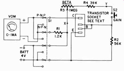
Fig. 819. Direct reading transistor checker using the VOM as the basic meter.
A VOM having a sensitivity of 1,000 ohms per volt is adequate for this job.
Table 8.1 is a calibration chart for this checker.
With the switch in the HI position, the current in the transistor base circuit will be determined by the 10,000-ohm resistor. The collector current will now be much larger than before. The two readings indicate the effectiveness of the transistor. Strictly speaking the ratio of the two divided by the change in base current is not equivalent to the transistor beta (current amplification) but it is close to it. The second figure includes the current through the base and the voltage divider, which would have to be subtracted to obtain beta. But these currents are very small by comparison.
A good transistor for audio amplification should show a ratio of at least 8 to 1 and anything less than 6 to 1 indicates a poorly functioning transistor. If both readings are very low, the transistor may have excessive resistance in the forward direction; if both are high, the transistor may be nearly shorted.
The main advantage of this simple transistor checking adapter is just that-it is simple to make and use. Many other adapters can be made using the current range of the VOM for indication, and using an external battery and external resistances.
A particularly useful tester is the one shown in Fig. 819. It uses the same principle: a change of collector current is measured as the base current is changed. But here the change is always made a fixed ratio, and the resistor required to make this ratio the same is calibrated directly to read the beta of the transistor. This tester uses the 1-rha range of the VOM, but you have your option of using this 1,000-ohms-per-volt type of meter or one with greater sensitivity.
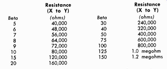
Table 8-1. Calibration of the checker shown in figure 819.
A special adapter with alligator clips can be made to accommodate power transistors. Fig. 820 shows the adapter, while Table 8-1 shows the calibration of the potentiometer for marking the beta range on the potentiometer scale. With switch SI in the proper position for an n-p-n or p-n-p transistor, and the transistor plugged in, read the leakage current through the transistor first.
Now depress switch S2 and adjust the reading on the meter to be exactly 0.5 ma more, and the scale on the potentiometer will indicate the beta of the transistor. In one operation you learn its amplifying ability and its leakage properties.
There are many other types of transistor testers but any of them can use the VOM as meter.
Checking tubes with the VOM
The VOM with some auxiliary equipment can be used to check any radio or TV tube for any of its characteristics which are of importance to use.-You can build a regular device for this, or you can set up each time you wish to check a tube. It all depends on how often you expect to test tubes and how much convenience you expect to create for yourself.
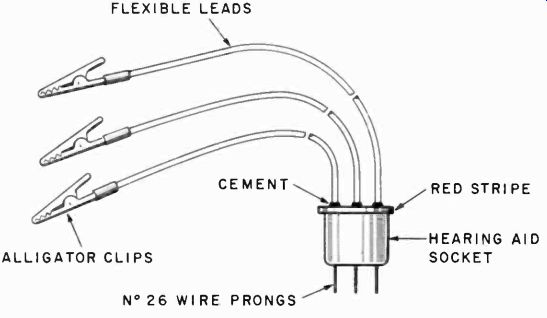
Fig. 820. Plug for testing power transistors, designed to go with the tester
of Fig. 819. The plug is made from a miniature hearing-aid socket with the
pins removed and wires inserted in place of the pins.
Use a stripe of red paint or fingernail polish as a guide on both the tester and adapter sockets.
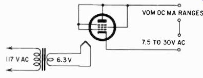
Fig. 821. Method of making an emission test with the VOM. All the tube elements
(except the cathode) are tied together, so the tube is tested as a diode. This
test is a check on the condition of the cathode.
Checking tubes with the VOM is not at all difficult once you know how to go about it. We have already discussed tube-filament continuity and a check for shorts.
The next most common test is testing a tube for emission. To do this we must ask the tube to deliver saturation current, which, depending on the tube, varies from 45 to 250 ma. But it is not difficult to figure out what it should be if you first check a tube which you know is performing well and compare its reading with the tube under test. Generally tubes such as 6V6 and 6L6 output types have over 200-ma saturation current, while rf amplifiers such as the 6AU6 and 6BH6 will show about 60 ma. In-between types, such as dual triodes 12AX7, 12AU7, and the 12AT7 will supply about 60 to 80 ma of saturation current.
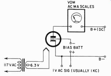
Fig. 822. How to make a transconductance test with the VOM. If the VOM cannot
read alternating current (and it usually cannot) obtain this information indirectly
by measuring the ac voltage drop across a known standard resistor in series
with the plate.
The process is very simple. The diagram is shown in Fig. 821.
All the tube elements, other than the filament and cathode, are tied together, and the meter is put in series with the tube and a relatively low-voltage ac supply. This should be about 30 volts or less for most tubes, although rectifier tubes may need as much as 70. The meter is used on the 1-amp, 500-ma or 250-ma scale, depending on what you have available. For some tubes, the 100-ma scale will be sufficient. The emission, which is as much current as the tube can possibly produce, is a direct indication of the state of the cathode. If this emission current is less than about 60% of what your healthy tube puts out, the tube should be replaced.
The next most interesting test is that for transconductance.
Again the tube must be supplied with filament current, but now we need some dc supplies to provide proper voltages for the elements and for the grid a 1-volt ac signal. The signal voltage can be anything from 60 to 1,000 cycles. Finally, we will need to measure ac milliamperes with the VOM.
The diagram is shown in Fig. 822. The measure of transconductance is the change in plate current with a 1-volt change in grid voltage. By applying ac to the grid, you can immediately read the change in ac on the plate, since now the grid voltage changes from 0 to 1 volt rms.
With the proper dc voltage on the plate (rated voltage), the transconductance will be exactly 1,000 times the meter reading in micromhos if you use a 1-ma ac scale, and proportionately more if you use a higher scale. Thus, a 10-ma ac scale would read 1/10,000 of the transconductance in micromhos, etc.
Several other tube tests can be made with your VOM. One of them, the power output test, also requires an ac milliampere measurement, and one, the amplification test, an ac voltage measurement. The power output test is seldom performed.
The amplification test circuit is shown in Fig. 823. Again a signal voltage is applied to the grid, and the resultant ac voltage at the plate, developed across the plate resistance, is measured.
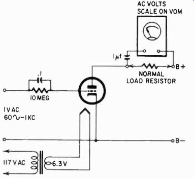
Fig. 823. Amplification test using VOM ac voltage scales. When testing pentodes,
the screen should get normal screen voltage. The amount of B plus must also
be what the tube will get in actual use.
This is a direct figure for amplification, since the signal on the grid will be made 1 volt again. In other words, the meter reading in volts is the amplification. Sometimes this test is substituted for the transconductance test, and you can see that, if we measure the voltage across a fixed value resistor, this voltage will be proportional to the ac developed, and thus proportional to the transconductance. But it is not exactly the same, for in the transconductance test there is no other load resistor besides the meter, while in the amplification test we use a normal load resistor for the tube.
Other tests are for gas and interelectrode capacitance. For the first, you need a meter reading only a few microamperes and, with the transistor-amplified VOM described earlier in this section, this can certainly be done. The process is to apply a bias to the tube until the tube is cut off, and then to measure the grid current of the tube with a sensitive microampere meter, while the plate has a normal voltage on it. The theory is that, while the tube is cut off through a high grid bias, no electrons can pass from the cathode to plate, so whatever electrons reach there must come from the grid, and this would not take place unless the tube is gassy.
Interelectrode capacitance is simply the measurement of the very small capacitances between the elements. Usually these are too small to be measured with a VOM, unless you calibrate the VOM to measure small capacitances with the series ac method used in identifying "mystery components" (see Section 7) . Measurement of interelectrode capacitance is seldom necessary except in vhf and uhf circuit design, and then you can usually rely on the manufacturer's figures.
There are many other ways to make the VOM serve as the basic meter in instruments. Those we have shown here are intended to be guides only to help you decide how you want to incorporate provisions for using the VOM with instruments which normally have their own meter. Remember one thing: when you have your meter tied up, you cannot use it for anything else. If you want to make an instrument using the VOM which must be used simultaneously with some other measurement, it would probably pay to build a meter into the instrument permanently.
Some solve this problem another way. Notice that many of the instruments described have as their basic meter a 1-ma unit. There fore some experimenters acquire, besides their VOM, several 1-ma meter movements which can be used for various instruments, and they rely upon the VOM when sensitivity is needed.
Also see: Link | --Guide to VOMs and VTVMs