Hall-effect current detector
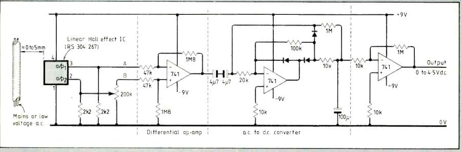
Alternating current flow in cables can be monitored using a linear Hall-effect device. This circuit detects current down to about 150mA.
The potentiometer is adjusted for equal voltages at points A and B with no current being monitored. Direct-current output can easily be fed into a computer for data-logging applications.
A. Smith; Llanelli Dyfed
Line-synchronized sawtooth generator
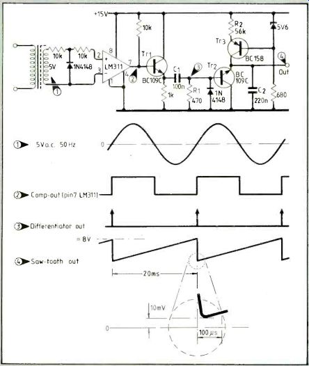
Sawtooth waveforms required for phase-control thyristor circuits must have a linear ramp, fast discharge to zero and a minimum dead time.
This circuit provides such a sawtooth and operates on a single supply.
Using a reverse-connected transistor gives a very-low Vy;c to f 1 to 10mV, although it requires more base drive as ß in this configuration drops to 0.1. Dead time, determined by R1/C1, is less than 100µs. A sawtooth repeating at every zero crossing can be obtained by inverting the comparator output, differentiating it then on-gating the two pulse trains to discharge Tr2.
V.B. Kuber; Nashik, India
AC power supply with limiting
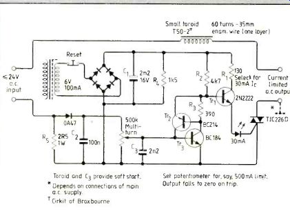
A simple current-limited a.c. power supply is handy for checking transformers and coils before applying full power. This supply can be used on its own or added to a d.c. power-supply unit with multi-tap mains transformer.
Alternating supply voltages from tappings on the main transformer are selected using a two-pole break-before-make switch. A useful selection of voltages is 3,4,5,6,20,22 and 24V. A separate small mains transformer of say 6V at 100mA powers the circuit.
Rectified current of 30mA feeds the TIC226 gate to ensure positive switching.
Voltage proportional to the alternating test current appears across Rç and is available, rectified, across the potentiometer. This potentiometer is set so that Tr:; triggers at the desired r.m.s. current limit of for example 500mA. As Tr;; conducts, Tr.; latches both transistors on, turning off the led and denying base drive to Tr1i the circuit under test is protected.
Pressing the reset button allows C1 to discharge, bringing the led on momentarily At this point the button is released. If the excess load is still present, the led flickers and then remains off.
-P.E. Thompson; Antibes, France
Stereo phase and level display
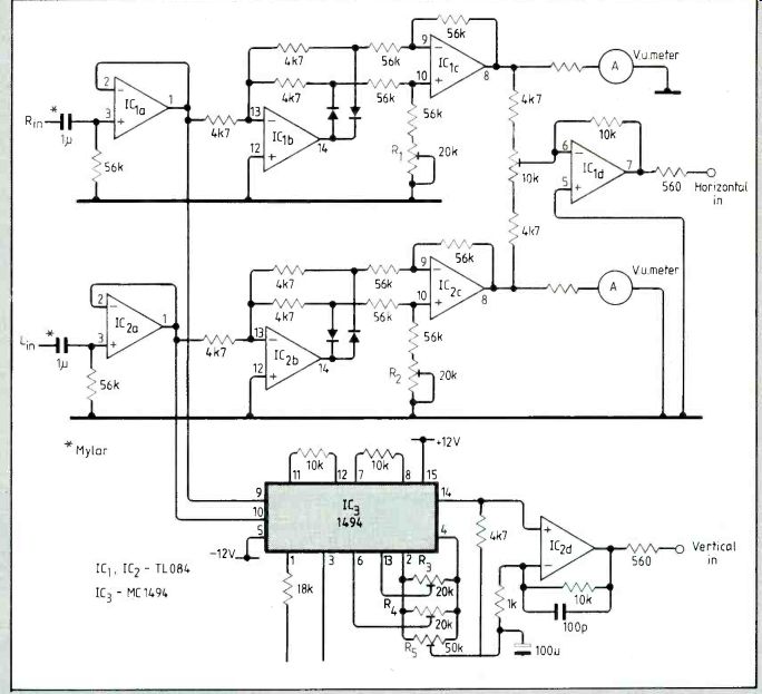
Live recordings have to be right first time, but when mixing multiple microphones by ear it is easy to make a listening error and have one of the microphones out of phase. Only after the recording is made can a fault like this be detected and by then it is too late.
By out of phase I mean that one microphone's position with respect to another is such that an acoustical phase shift occurs, causing coloration at certain frequencies. If a disc is made from the recording, too many out-of-phase signals cause undesirable needle movements, resulting in wooliness.
With this circuit, any general-purpose d.c.-coupled oscilloscope can be used to display a left-minus-right signal on the horizontal axis and a left-multiplied-by-right signal on the vertical axis.
Buffered left and right signals feed two rectifiers providing positive and negative signals for subtraction; rectifier symmetry is, balanced using R1, 2. If the two input signals are identical, the 10k-ohm potentiometer can be adjusted for null.
Simultaneously, both channels feed an MC 1494 multiplier. Resistor R3 is adjusted for null output with a left-channel signal only and R4 nulls output for a right-channel signal only.
Because IC:3 is a multiplier, output follows a square law. A logarithmic amplifier could be used to linearize this circuit but balancing such an amplifier is difficult so it may not be worthwhile. The v.u. meters are optional.
Don Goodman, Rubin Academy of Music,
-Tel- Aviv University, Israel
Sensitive dip oscillator for titrations
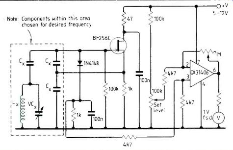
In FET r.f. oscillators a diode from gate to earth is often included to stabilize output voltage. Popular belief is that this produces a bias voltage by rectification, thus reducing circuit gain.
This cannot be so because the circuit still functions in the same way if the series capacitor in the tuned circuit is omitted and the gate thus connected to earth through.
The diode seems to work by clamping voltage across the tuned circuit to the diode's forward voltage level.
Absorption of power from the tuned circuit, such as occurs when a tuned circuit resonant at the oscillator frequency is brought near, causes a reduction in diode current.
By placing a low value resistor in series with the diode, this clamping current may be sensed, amplified and displayed on a meter. In this conventional Clapp oscillator diode current typically develops 10-100mV across the Ike resistor.
The circuit can be applied as a very sensitive dip oscillator or as a metal detector. In analytical chemistry, I have used the circuit for high-frequency titrations. The cell is the inductor, which consists of a few turns of wire round a breaker.
-Lionel Sear Truro Cornwall
----------------------
Also see:
Link | --Mains communication without tears
==========
(adapted from: Wireless World , Dec. 1986)