HEAT TRANSFER
I was very interested to read the article on heat transfer in the August 1986 issue. Whilst Dr Smith covered the subject from the viewpoint of transistor failure, my interest in the subject lies in reducing temperature-generated distortion (t.g.d.) in audio amplifiers. Temperature-generated distortion occurs when the gain or base-emitter voltage of a transistor varies as a result of instantaneous changes in its junction temperature. When a transistor is handling a large audio signal, its instantaneous heat dissipation is equal to the instantaneous product of current times voltage. The variation in power dissipation causes the junction temperature of the transistor to rise and fall in relation to its ability to dissipate the heat generated.
I was surprised to note from Dr Smith's article that a TO220 transistor has a much lower thermal resistance from junction to case than a TO220. This is an area that I had been intending to research and a check through a manufacturer's catalogue yielded the information that the thermal resistance of different transistors reduced as the power rating increased. One exception was a transistor which had a much higher Ft arid this had a thermal resistance about 10 times those of similar power rating. As a practical test, I replaced a pair of TO126 transistors rated at 12.5 watts with a pair of TO220 rated over 50 watts in part of an audio amplifier circuit in which the power consumption was 60 milliwatts per device. The difference in sound quality due to lower temperature generated distortion was easily audible.
Graham Nalty Borrowash Derby
FREQUENCY ALLOCATIONS
Following Mr H.D. Ford's letter (August, 1986) I felt it would be worth explaining the current situation regarding frequency changes to the long-wave broadcast band.
At the World Administrative Radio Conference (WARC) held in Geneva in 1979 it was decided to bring all long-wave broadcast frequencies on to multiples of 9 kHz. In effect this means decreasing all long-wave broadcast frequencies by 2 kHz.
The reason for making this change is to help to reduce the effect of interference that can result from the harmonics or intermodulation of two or more broadcast signals. Any product formed in the receiver by these processes will, if all the carriers are located at multiples of 9 kHz, fall on a carrier frequency. This causes considerably less objectionable interference than if the product were to fall at say 2 kHz from the carrier as it could with the present situation.
Locating carriers at 9 kHz multiples also simplifies the design of receivers that use synthesized local oscillators to cover both the long and medium-wave bands.
All long-wave transmitters in Europe and Africa (Region 1)
operating between 200 kHz and 236 kHz are due to change frequency on 1 February 1988.
The BBC's Radio 4 long-wave network will change from 200 to 198 kHz on that date.
Obviously, this change is going to cause difficulty for some people who use 200 kHz as a frequency standard. This point was considered at the WARC, but since the long-wave signals involved are actually broadcast transmissions, and not specifically intended for time or frequency standards, it was felt that the needs of broadcasting must take precedence. It would, of course, have been impossible in any case for the UK to keep using 200 kHz when the rest of the world changed to 9 kHz multiples.
Henry Price
-Engineering Information Department BBC London
ELECTROLYTIC CAPACITORS
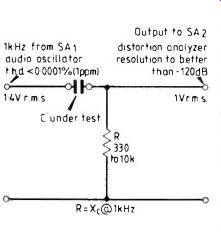
I would like to join in the great capacitor sound debate as after a great deal of practical work I generally have to agree with most of Mr Self's opinions. From purely static harmonic distortion tests, using an SAl and SA2 oscillator and distortion meter, I have found that all modern types of polyester, box or humbug type (C280), polypropylene, polycarbonate and Mylar capacitors when connected to the circuit of Fig. 1 do not exhibit any measurable distortion down to my limits of 0.0001% (1 ppm). However when using some, but not all, types of ceramic discs ...
... they can have up to 100ppm distortion irrespective of value, types unknown. Also all the miniature ceramic multilayer types and many surface mount types also have between 10 and 100ppm distortion. The distortion is always third-harmonic, indicating a symmetrical distortion of both halves of the sinewave.
It is also interesting to note that virtually all the humbug style capacitors I could find of over 10 years old also have this mysterious up to 100ppm third harmonic. The maximum distortion occurring when X, = R. A very surprising result perhaps is that electrolytics do not exhibit any distortion without bias or with positive bias but show increasing signs of second harmonic with at least 2V d.c. reverse. This was only tried on a small sample of 0.47p.. One point on which I would like to disagree with Mr Self is that of old plugs and sockets having distortion. This is also true; those with oxidized, tarnished contacts exhibit third-harmonic distortion from zero to around 50ppm, dependent upon movement and contact efficiency, the effect improving as the contacts are moved repeatedly, presumably due to cleaning. From a practical point of view, it seems reasonable that any contact will have some resistance and a poor dirty contact will have a resistance which can be partly voltage dependent. This would be symmetrical, therefore giving rise to third harmonic distortion.
Also very tarnished i.cs fitted into i.c. holders exhibit distortion, as does an oxidized p.c.b. inserted into an edge connector.
One explanation of the 'old' polyester capacitors having relatively high distortion is that over the years moisture has entered via the leadouts, oxidizing the metal foil and contacts. Scraping and tinning the leads has no effect.
On the subject of d.c. component, I must again agree with Mr Self in that any signal shape coming from a source such as a cartridge, microphone, tape, tuner, etc. cannot have a d.c. component even though the positive and negative peak values are widely different, the average will still be zero. If signals did somehow receive a net d.c. offset dependent upon wave shape, then clearly there would be an overall increase in the low-frequency spectrum giving a very muddled sound.
However, has no one in the audio field ever heard of d.c. restoration? This is the technique used by video engineers to restore the d.c. level lost from a picture in the path from transmitter through a tuner and i.f. to the output stage.
Most low cost black and white TVs have simple a.c. coupling throughout, thereby losing any d.c. present at the source. This explains why the contrast level on a black and white tv often varies with picture content. This is totally unacceptable for a colour tv and so d.c. restoration is used. This consists in its simplest form of a black-level clamp potential formed by R1, R2 and a diode Dl (Fig. 2). The capacitor stores the most negative peak; the whole signal then stands upon this, thereby finding an artificial d.c. level. It is, in fact, peak rectifying without further smoothing. The capacitor is forced to change its change on the negative cycle due to the low impedance diode but meets a high impedance on the positive cycle.
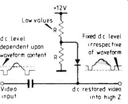
---- 12V Low values dc level dependent upon waveform content; Fixed
dc level irrespective of waveform Zl 1 Video dc restored video input
into high Z
This circuit when fed with a steady state sinewave does not, as would be expected, clip the negative side, but simply changes its d.c. level. The steady-state distortion is then very low as measured after a short period of time. The first few cycles are severely clipped until d.c. restoration is complete. Clearly then, if an amplifier has a nonlinear input impedance, such as a simple common-emitter stage, d.c. shift will occur, dependent upon the music waveform giving rise to an increased I.f. signal spectrum. It is therefore important to design preamplifiers with a constant open loop input impedance, which is fortunately easy with modern ICs.
The problem comes with power amplifiers. It is widely accepted that the power-amplifier stages often clip on transients: these can be positive or negative and therefore, if a.c. coupled, will rise to d.c. changes with a corresponding recovery time. In the seventies it was fashionable to drive an amplifier into clipping with a sinewave for several cycles then remove the drive and measure the recovery time. This, being symmetrical, does not normally give significant d.c. offsets unless the amplifier really is sick, but the same technique should be used with a signal with a larger peak on one half cycle than the other.
At the point of clipping since the feedback loop is broken the input impedance drops, giving the effect of d.c. restoration.
Amplifiers with low feedback will therefore sound better giving less d.c. and low-frequency spectra when asymmetrical clipping occurs.
The complete answer is obviously not to a.c.-couple the input or feedback networks to the power amplifier and then any amount of asymmetrical clipping can occur without generating any extra l.f. components.
Preamps do not normally clip and therefore can be a.c.-coupled safely, provided their input impedance remains constant over the whole operating range and also that the feedback factor is also constant.
L. Sage; Sage Audio; Bingley, West Yorkshire
SHOOT THAT POSTULATE
A scientific hypothesis or postulate is a peculiar beastie. It seems to be born of a synthesis of experimental data combined with an extremely variable amount of intuitive leaps in the dark; the mix will probably always defy attempts at a precise definition. Once introduced, however, we are on safer ground with it as we can verify its "truth" by the severe test of comparison with experiment, and although no amount of corroboratory evidence will ever prove it true, it requires only one properly established, repeatable bit of evidence to disprove it. There is no other scientific basis upon which we can say it is wrong. Nor can any flat statement be accepted for a single moment, no matter what the 'authority' of its author, without the factual evidence to support it, either for or against.
For more years than I care to admit, and no doubt in common with many others, I have sought such evidence to disprove Einstein's "second postulate", but I must confess failure. I have seen much that corroborates it, but not one single, positive fact to contradict it. I am glad to see that this evidence has now become available, otherwise some of your correspondents (video, for example, Mr Winterflood, Feedback, August, 1986) could not possibly make the totally unequivocal statements that they have done. It is unfortunate that none of them has actually bothered to quote the experimental evidence or any published reference to it, probably because they think that it is better-known than it in fact is. May I ask that they remedy the omission and give us chapter and verse?
Alan Watson; Pollenca Mallorca
SYNCHRODYNES
I was delighted to read the series of articles by J.L. Linsley Hood on the synchrodyne a.m. receiver earlier this year. They were long overdue.
I have followed with interest the progress of the synchrodyne from the date of its first announcement by D.G. Tucker shortly after World War II. It was (predictably) instantly rejected by the commercial radio manufacturers, wedded as they were to the mass-produced superhet, but later rescued from oblivion (again rather typically) by the amateur radio community under the pseudonym of "direct-conversion receiver". The amateurs, with no commercial axe to grind, came to recognize its special virtues as an efficient receiver of shortwave a.m. signals, needing no expensive or sophisticated components and easily constructed with the minimum of test equipment.
My only reservation about the Linsley Hood circuitry is that it is rather complex and, in view of the rarity of practical references to the synchrodyne system in the pages of WW, may cause some readers to conclude that all synchrodyne receivers are necessarily complex.
The word rarity is not misplaced. If we ignore block schematics referred to in passing, readers of WW whose loyalty is exclusive have had to wait (I think) since August 1948 to see a diagram of a practical synchrodyne circuit.
As the astute Cathode Ray was quick to point out, the two broadcast bands (for which the recent circuitry was designed) are used almost universally for reception of a few powerful stations and the needs of knob-twiddlers are hardly worth catering for. So half a dozen preset capacitors and as many switches can, in practice, make all muting circuitry redundant.
The same goes for circuitry designed to extend the receiver's pull-in range, a great help when hand-tuning. Given a switched-station design with an oscillator employing silicon semiconductors and fed from a voltage regulator device, the frequency drift in a domestic environment will be only a small fraction of the normal pull-in range. In practice, whistles caused by drift just don't occur.
Along such lines a fairly simple synchrodyne is possible, perfectly adequate to demonstrate the system's special advantages of low distortion and ease of construction, and above all its unique feature of post-detection selectivity control.
Such a design in the pages of WW could well represent an attractive introduction to synchrodyne construction and perhaps act as a stepping-stone to the more ambitious continuous-tuned receivers as exemplified in Mr. Linsley Hood's contribution.
-D.B. Pitt, Nottingham
ENGINEERING COUNCIL EXAMINATION
During the academic year 1985/6, I gave a course of lectures to two classes for Courses 24I (Fields and Circuits) of the Engineering Council Part 2 Examination. The full course (all 6 papers) is very troublesome for most students and I would like to make some comments based on my experience.
The purpose of the Part 2 Examination is to provide a means for technicians and technician engineers to obtain the academic qualification for professional engineering status.
Before a student can take Part 2 he must have passed Part 1 or its equivalent. But this does not mean that a topping-up operation is adequate. From the format of the questions on the papers I would say that the real purpose of the examination is to test the roundedness and completeness of a technician's information. He could make heroic efforts collecting and studying course information but still be unable to pass an actual paper. For example text books, which are the normal source of information, do not usually provide answers to specific examination questions. A student intending to pass Part 2 must search around the various topics and acquire a proper understanding of the principles.
His answers will reflect his understanding and overall command of the subject. This is very different from the techniques required to pass Part 1. Essentially the Part 2 probes for an understanding of fundamental principles and to assess a student's ability to manipulate those ideas. I am not criticizing the examination, but trying to point out the requirements that a student must satisfy for a successful result.
I would consider my only serious problem to be that classes must sit an examination which is set and corrected by another person(s). I could spend considerable time on a number of topics that might not appear on the paper. This happened with one of the classes because only a limited amount of time was available and the full course could not be covered. The papers can surpriselecturers as well as students. I have no criticism of the syllabus, which compares very well with a degree course at a university or technical college.
I never sat the examination and consequently cannot comment from a student's viewpoint. However, I noticed that most students rarely tired of having examination questions explained and answers thrashed out. I used approximately two-thirds of the lecture time doing questions, but I cannot say that this approach improves a student's chances of getting through over any other method.
The full examination consists of six papers. For a student to pass all six papers at the same sitting is a considerable achievement. Under the present rules he must take three or more at the first sitting and I would favor taking three or four.
Failure in any paper brings disappointment and frustration but I would always recommend a second attempt to a serious student.
These are purely personal comments. I would welcome the views of lecturers and students.
Brian P. McArdle; Dundalk Co Louth
Eire
----------------------
Also see:
Mains communication without tears
Developments in packaging (Dec. 1986)
==========
(adapted from: Wireless World , Dec. 1986)