Capacitor discharge unit replaces magneto ignition to give new life to garden machinery
by John Robins
John Robins is a pseudonym for a well-known circuit designer now working as a consultant.
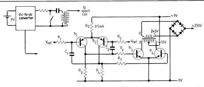
Fig. 1. Simplified d.c. converter using base and emitter coupled multivibrator
actually uses Darlington transistors for the output pair.
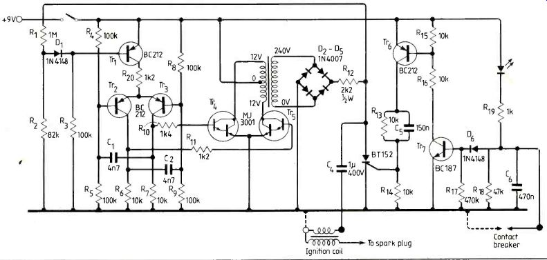
Fig. 2. To prevent the voltage rating of the storage capacitor from being
exceeded control transistor Tri1 is added. If the output voltage exceeds
limits set by R1 and R2, D1 conducts to reduce oscillator drive.
The initial requirement for a dry battery c.d. ignition system is a d.c. converter to generate a supply of some few hundreds of volts to which an energy storage capacitor could be charged, preparatory to its discharge through the primary of the ignition coil.
To a first approximation, the spark energy will depend on the energy stored in this capacitor, which is 0.5(CV2). This is in joules if C is in farads, and, conventionally, energy figures in the range 30-120mJ have been suggested 1'2. A 1 µF capacitor charged to 250V with a stored energy of 62mJ would offer two advantages over a higher voltage, lower capacitance system. The first is that the use of a 400V d.c. capacitor offers a sensible safety margin and such capacitors are easier and cheaper to obtain than higher voltage units. The second benefit is that such an operating voltage would be readily obtainable from the primary winding of a small 240V mains transformer. If this could be used as the step-up unit, it would save the difficulty of winding a special unit.
Most conventional d.c. converter circuits . employ self-oscillating systems, with the positive feedback required to sustain oscillation derived from additional transformer windings. In his article', Cooper proposes the use of a low power multivibrator to drive the inverter transistor, and this seems an eminently sensible move in that it allows a readily determined operating frequency independent of the transformer output load, and avoids difficulties in start-up if the supply or transformer load conditions are such that the oscillator fails to oscillate.
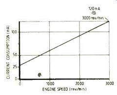
Fig.3. With the intermittent use a single-cylinder two-stroke engine
might get a 9V dry battery could last up to several months-less than the
cost of fuel.
==========
The case for electronic ignition The energy of the spark from a magneto depends on the current in the primary coil, which depends greatly on the speed with which the pole pieces pass the fixed coil unit. So if one's arm is weak or the engine doesn't turn freely, the spark can be inadequate to start the engine.
Additionally, with the passage of the years, vibration and age can weaken the strength of the magnet, or worn crankshaft bearings can increase the air gap between the magnet and the magneto coil poles, which will reduce the energy of the magneto and make the feeble slow-speed spark even weaker.
Finally, and more catastrophically the ingress of moisture into the coil windings can cause electrical leakage or chemical corrosion of the fine secondary wire.
With a new machine, replacement of the flywheel unit or magneto coil shouldn't be difficult but in the case of an elderly appliance the model may be obsolete, or the makers out of business.
A number of electronic ignition systems have been described in the technical press, but these have normally been intended for use with multiple cylinder, relatively high performance motor car engines, for which high engine speed was a greater consideration than economy of d.c. supply, so this article takes a fresh look at the circuit possibilities with the specific aims of achieving good d.c. economy and simplicity of construction.
==========
The basic circuit that I used is a symmetrical, base and emitter-coupled multivibrator of the type shown in Fig. 1. The operating frequency is effectively determined by C1, C2, R1 and R5 and this delivers an alternating square-wave drive to the bases of Tri and Tr4 via the current limiting resistors R6 and R7. These transistors are Darlington types, to reduce the required drive current through Tri and Tr2. I used MJ3001s because they were to hand, but less expensive devices such as the TIP121s would be entirely adequate.
In the collector circuit of the power stage I used a small mains transformer with a centre-tapped low voltage winding. The high voltage 240V a.c. winding is used with a rectifier bridge to supply the energy storage capacitor.
In general, the maximum output current which could be drawn from such a circuit will increase as the operating frequency increases, and some experimentation with two small' p.c.b.-mounting transformers of this type, one 1.5VA and one 3VA, showed that both were quite happy up to a few kHz.
The standing 'quiescent' current of the inverter stage increased with frequency, especially beyond about 3kHz, as the core losses increased.
An operating frequency of about 1kHz was therefore chosen as a reasonable compromise between these two conflicting requirements. This gave a standing quiescent current of 15-20mA in the prototype when operated from a 9V supply, but would provide an adequate high voltage supply to allow operation at 3000 rev/min, which seemed a suitable upper speed limit.
Secondary voltage control
Under light load conditions, it is probable that the rectified secondary voltage from the step-up transformer could rise to high levels due to the peak rectification of inevitable voltage spikes, and this could cause the working voltage of the energy storage capacitor (C4 in Fig. 2) to be exceeded.
The oscillator/drive circuit has therefore been elaborated, as shown in the full circuit diagram of Fig. 2, to include a control transistor in the multi-vibrator emitter circuit. This is normally turned full on by base current supplied through R3. However, if the inverter output voltage increases beyond predetermined limits, set by Rs and R2, the diode Ds conducts and progressively 'throttles back' the oscillator drive.
This also helps to cut back the quiescent oscillator current once the energy storage capacitor is fully charged.
Since it was intended that the unit would operate from a 9V dry battery it was not thought worthwhile to stabilize this supply, though a very low output current regulator in the emitter circuit of Tri would be all that was needed.
HV capacitor discharge circuit The output voltage from the inverter step-up transformer is rectified by a bridge-connected group of four 1N4007 diodes and feeds the energy storage capacitor through the limiting resistor, R12, which serves to restrain the momentary increase in oscillator current when the capacitor is discharged.
Since Coopers observes that failure of capacitor discharge units is almost always due to the failure of the thyristor, I decided to use a generously rated (13A, 600V) component for this, since the difference in cost between this and a less rugged device was very small.
The thyristor should be fired when the contact breaker points open, and it is very desirable that it should not fire again when the points reclose.
This requirement is met by the circuit built around Tr1 and Tr2, which fires the thyristor cleanly and reliably without the need for a `disc', for which, in any case, the available d.c. supply voltage would be too low.
Contact breaker points It is normally assumed in the design of capacitor discharge electronic ignition systems that the lower the current which passes through the contact breaker points, the better will be their longevity. Up to a point, this is true, but the points normally operate in an atmosphere of oil vapor from the engine, and it is desirable that enough current should flow through these points to burn off any thin insulating film which may form. This is unfortunately incompatible with the design requirement that the direct current consumption for the unit should be as low as possible. I therefore opted for a 1kil resistor for R19, with an led in series with it. If it is suspected that the points may not be closing satisfactorily, the led will verify this point. Also, the 0.47µF capacitor across the points will contribute a small amount of discharge energy (234) to assist in keeping the points oil film free.
The whole unit fits comfortably within a small (114x64x55mm) diecast metal housing, with external leads to the primary of the ignition coil, battery, and contact breaker points.
The relationship between running speed for a single cylinder two-stroke engine and d.c. supply demand, at 9V input, is shown in Fig.3. For the sort of usage such machines get, one or two hours at a time, a 9V dry battery could well last many months, and cost substantially less than the petrol used to power the appliance.
For the benefit of those whose skills are mechanical rather than electrical, convert the existing magneto-operated c.d. unit as follows. Disconnect the h.t. lead from the magneto to the spark plug, and the internal connection between the magneto high current (primary) winding and the contact breaker. The contact breaker will almost invariably consist of an insulated moving contact and a fixed contact connected to the chassis of the machine.
Identify the insulated point, from which the magneto primary winding is to be disconnected, and provide an adequately robust connection from this point to the c.b. input lead of the c.d. unit. Provided that the carburetion is satisfactory, the machine should start easily and run freely.
References
1. Cooper. R., Wireless World, March 1982, pp74-76 and 87
2. Anderson. D., Wireless World, November 1974. p426.
3. Watkinson. J., Wireless World, July 1974. pp216-219.
----------------------
Also see:
Link |
Link | --Mains communication without tears
==========
(adapted from: Wireless World , Dec. 1986)