Thirty years development--from image transfer to digital conversion and onwards.
By S.M. EDWARDSON and C.K.P. CLARKE
The conversion of television signals that have originated on one scanning standard to provide signals on a different scanning standard presents problems that have taxed the ingenuity of television engineers for well over thirty years. In that time, the methods used for conversion have undergone several major changes: first from optical methods to analog signal processing and then to digital signal processing. These changes have come about partly as the result of changes in technology and partly through a progressively improving understanding of the underlying theory.
The conversion methods have developed from the relatively simple techniques used to alter just the number of lines per picture, while keeping the same field rate, to those in which the field rate is altered as well. As the conversion methods have developed, there have been corresponding changes in the ways of visualizing the action of the conversion process. Some have been based in the time domain, synthesizing intermediate lines or fields and correcting their timings, while others have used a frequency-domain representation to view the process in terms of low-pass filtering and resampling.
Transatlantic conversions, changing be tween the 625/50 (625 lines, 50 fields per second) and 525/60 standards, (which grew out of the different mains electricity frequencies used in Europe and North America) have become particularly important to allow the exchange of programs between these two major program producing areas. A further complication that has arisen over the same period is the inclusion of color. This has prompted the development of special techniques for handling color at each stage in the evolution of converter technology.
IMAGE-TRANSFER CONVERTERS
The image-transfer or optical method of standards conversion) consisted of pointing a television camera, working on the output standard, at a television picture on a cathode-ray tube display (c.r.t.) working on the input standard. In principle, therefore, the intention was to reproduce an image of the original scene in front of the camera so that it could be rescanned on the new standard. Clearly, in such a circumstance, the geometrical matching and the stability of the two scans were very important to the effectiveness of the technique. The need for synchronizing the two signals, so that the camera scan followed appropriately after the c.r.t. scan, was also important, Flicker and movement portrayal. The combination of the c.r.t. and the camera differs somewhat from the case in which a television camera views a normal scene. The light from a normal scene falls continuously on to the camera tube, to be integrated as an accumulating charge, whereas the light from the converter c.r.t. is not continuously present. Instead, a bright 'writing' spot traces the raster on the c.r.t. screen where it remains only during the afterglow period of the phosphor, which has an approximately exponential decay. With normal phosphors the persistence is very short, being only a few line periods, so that the image dies away rapidly. The 'reading' beam of the camera then discharges the integrated signal from the previous field period, but the signal level varies with the relative field phasing of the c.r.t. 'writing' beam and the 'reading' beam in the camera tube.
This problem is particularly noticeable when converting between standards with different field rates 2.3). Then there is either a surplus or deficit of fields or parts of a field within the scanning period of the converter camera tube. The display brightness at any point in the field is renewed as the scanning spot passes and then rapidly dies away. If the field period of the output standard is of shorter duration than that of the incoming signal, then, at one particular phase relationship, the camera receives no exposures at all. Similarly, an output field longer than that of the incoming signal can embrace two full exposures from the short-persistence display tube. Either of these conditions creates a brightness variation in the converted signal at the difference frequency between the field repetition rates and results in a bright or dark bar travelling vertically through the picture. However, it was found that this problem, and the related one of field phasing, could be reduced substantially by the use of a c.r.t. display phosphor with much longer persistence than normal.
The advantage of using longer persistence c.r.t. phosphor was lessened somewhat by the fact that it exacerbated the problems of movement portrayal. Moreover, the three camera tubes in general use at that time (image-orthicons, cathode potential stabilized Emitrons and vidicons) all tended to leave residual images. These resulted primarily from the incomplete erasure of the stored charge by a single scan of the camera tube target and an image could still be discernible as many as ten fields after it was originally scanned. This effect, in combination with the use of long-persistence phosphors in the c.r.t. produced rather poor portrayal of movement, the main impairment being due to multiple imaging.
Line structure and vertical resolution, 'Line beating' was a problem that arose when the number of lines per picture was changed.
This was again a form of brightness modulation of the output picture, at the difference between the two spatial line-frequencies. It resulted from the discrete nature of lines on the c.r.t. display which thus did not form a continuous image. The scanning lines of the camera tube could then fall between or on top of the lines of the original scan as the phasing of the two line structures varied down the picture. This effect, coupled with slight geometrical differences between the rasters in the c.r.t. and the camera, gave rise to moiré patterns on the converted picture.
These patterns could be quite severe and had to be reduced by broadening the display spot, for example by introducing sinusoidal vertical 'spot-wobble', although this unavoidably had an adverse effect on vertical resolution. Because of these effects, all image-transfer converters were operated on a field-by-field basis, thereby losing any extra vertical information carried in the interlaced fields. An additional benefit of this field-by-field approach was that it tended to improve the portrayal of movement, by preventing double imaging (resulting from displaying two fields at once) from adding to the multiple imaging effects caused by the dyna mic characteristics of cameras, as described above.
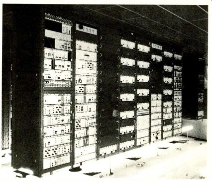
Fig.1. BBC analog converter at Television Centre.
In the circumstance where the input and output field frequencies could be made exactly synchronous, it was possible to select a particular phase of the input and output signals in which the vertical resolution was significantly improved. This was achieved by phasing the output scan to take equal contributions from two interlaced input fields. Unfortunately, this phase was found to be the most disadvantageous for movement because the use of two fields gave a double edge to any moving object, in addition to the normal multiple-imaging effects of the display tube and the camera.
Standards conversion of color pictures. An extra problem that was addressed in later field-rate image-transfer converters was that of converting color signals. This was approached by adding a second c.r.t and camera, amounting to an additional standards converter.
The first then carried the luminance component of the picture signal whilst the second carried the color difference signals in the form of a phase modulated carrier. This added a new dimension to the problems of matching, requiring accurate correspondence between both the c.r.t. and camera scans in both the luminance and color channels. Color trans-coding was achieved by, first, transcoding from the original color system, either PAL, NTSC or SECAM, into the special form of coding used only during conversion and then transcoding again to provide the required output color signal.
Limitations of image-transfer methods.
Throughout their development, only limited facilities were available for controlling the performances of image-transfer converters, such as choosing a display phosphor time-constant or adjusting optical or beam focus.
In essence these techniques were used to filter out the unwanted products of the original scanning standard, but did not give much freedom of control of the low-pass filter characteristic. In practice, the c.r.t. could not give out 'negative' light, so limiting the effective scanning aperture to positive-only values. Because of this, only a relatively slow roll-off frequency characteristic could be achieved, which resulted in a noticeable loss of picture detail. Similarly, flare in the various optical components, especially the glass face-plate of the c.r.t., also caused a loss of detail, particularly in bright areas of picture.
For moving pictures, the temporal filtering effect was determined by the exponential decay properties of the c.r.t. display and the camera target discharge process. This resulted in an asymmetrical impulse response, akin to that of a recursive filter, and was less suitable than a symmetrical response such as might be produced by a transversal filter.
In converters used to change both the number of lines in the picture and the number of fields per second, the problems of maintaining accurate matching between the scan geometries of the c.r.t. and the camera were increased. In addition, because the timing of the scans relative to one another was changing systematically, flicker, particularly that associated with line beating, became more noticeable. The use of long-persistence phosphors in the display did not provide a complete answer to this problem.
It ensured that the amount of light integrated by the camera tube did not vary appreciably as the phasing of the two scans altered, but had the disadvantage of making movement very blurred, as stated earlier.
Over and above these problems and short comings, there existed the need for careful maintenance and skilled operation. The cleanliness of the optical system and the adjustments of focus and raster sizes are just a few examples of the requirements to produce consistent and acceptable results.
ELECTRONIC ANALOG CONVERTERS
The fundamental nature of the problems with image-transfer converters made it very desirable to seek a wholly electronic solution in which the signals did not have to go through an intermediate optical form. Electronic conversion had the potential to eliminate many of the problems already out lined and to give much greater freedom to control the filtering effect of the transfer.
However, whereas the processes involved in an image-transfer conversion are reasonably easy to visualize, those in the non-optical, electronic case are more difficult.
In electronic standards conversion, the picture signal occupying each active-line period of the input television signal was seen as a discrete element to be reformatted to match the synchronizing pulses of the out put standard. A means of changing the number of lines in the picture was needed so that some lines could be discarded or new lines produced, and processes such as time stretching or compression were used to make the new lines fit the active period of the output standard. The filtering action implicit in this transfer of signal information was determined by controlling which input lines were used in the formation of each output line. These processes required the development of methods of storing portions of the input signal until required for the output, of altering the line duration and of combining lines together.
Changing the active-line duration. An electronic store for stretching or compressing input lines to match the active-line period of the output standard was formed by a series of capacitors. Each capacitor was used to hold a charge proportional to the picture brightness at one point in the line, so as many capacitors were needed as there were discrete picture elements in the active-line period.
The charge was stored by using electronic switches to connect the input signal voltage to each capacitor in turn as the line scan progressed. Then the change of line duration could be achieved by 'reading out' the stored values in the same order, but at a different rate.
The use of discrete storage elements in this way caused the input signal to be sampled and may well have constituted the first application of 'horizontal' sampling in a television context. Because of this, some pioneering work into the filtering requirements and the impairments resulting from video sampling was carried out at this stage. This showed that, for the video signal bandwidths then in use, about 550 elements (capacitors) were needed for a time-redistributing line stores.
With the analog devices then available, there was a certain amount of variability in the efficiency of the switching and storage circuits. As the same switching and storage unit was used for corresponding picture elements on consecutive lines, this variation caused a modulation of the output signal which could appear on the converted picture as a fixed pattern of vertical striations. Very careful matching was required to reduce this pattern to a sufficiently low level to avoid a visible pattern.
Line-store conversion. With standards converters operating between asynchronous in put and output field periods, any interval up to a complete picture period may elapse between the moments at which a given picture element is 'written' at one standard and 'read' at the other. In such converters, therefore, provision must be made to store an entire picture period of video information in the converter. In terms of the capacitive storage cells described in the previous section, this would have required about 200,000 separate capacitors. In an image-transfer converter, this storage capacity was provided by the persistence and the camera charge integration process. If, however, two standards having the same nominal field period are rigidly synchronized, so that their field periods are coincident, it can be arranged that each picture element is read out of the converter within one output line period of being written in. In that case, therefore, it is necessary to provide storage for only one line of video information. Such a device, known as a line-store converter, was then able to replace the image-transfer method in application such as 625/50 to 405/50 conversion. This avoided the careful adjustment and constant attention from a skilled operator required with the image-transfer equipment. Because of this, it was possible to install a line-store converter at each 405-line transmitter, thus avoiding the need to pro vide duplicate distribution for the 405 and 625-line broadcasts.
Nevertheless, the construction of suitably matched storage and switching devices operating at, for the mid-1960s, very high switching speeds represented a considerable problem. The main difficulties were those of distributing the video and switching control pulses to the successive stages of the store without allowing crosstalk from the input to the output. This was accomplished with manageable complexity by using diode-bridge switches and low-loss transmission lines for the video and pulse signal distribution10.
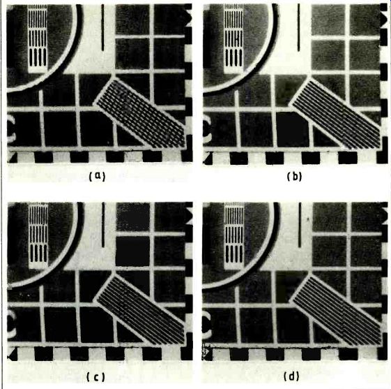
Fig. 2. Line-store conversion zero-order interpolation(a); 2-ordinate
linear interpolation (b); and 4-ordinate optimized.
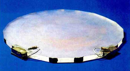
Fig.3. Quartz delay line.
Ultrasonic delay lines. In circumstances in which the input and output field rates are different, or where the input and output fields cannot be rigidly synchronized, much larger amounts of storage are required. This can be provided by storing the signal in quartz ultrasonic delay lines 11. In analog field store standards converters the basic conversion operation was achieved by a network of switched delay units and by-pass routes that determined the delay to which each television line was subjected. In this 'main store' process, lines could be repeated or omitted so that the average line frequency of the output signal from the main store was that of the final output standard 12.
Ultrasonic propagation through a solid medium can be up to 100,000 times slower than that of electromagnetic waves in free space. In addition, certain substances exhibit fairly low absorption of acoustic or ultrasonic energy and therefore make suit able transmission media for delay devices.
Class can be used for fairly short delays, although natural or synthetic fused quartz is preferred for longer delays in which lower absorption is needed. A long transmission path is obtained in a small volume by adopting a form of construction in which the acoustic wave is internally reflected between the facets of a polygon. The acoustic wave is launched into the quartz and collected from it by means of piezoelectric transducers, such as quartz crystals.
In the development field store standards converters, the main factors found to limit the performance of such delays were their insertion loss, their group-delay and amplitude-frequency characteristics, and their susceptibility to producing spurious signals. Many of these factors were improved by amplitude and group-delay equalization and by operating the longer delays at a high temperature (75°C) and at a common centre frequency of about 30MHz. Because the value of delay was temperature dependent, the quartz delay lines were housed in accurately controlled ovens to maintain stable temperature during operation.
Several factors contribute to the insertion loss of a delay line. The transducers, which use lead backing to damp their frequency and group-delay characteristics and to re duce reflections from the transducers, pro- duce about 36dB loss. Beam spreading and energy absorption losses in the quartz depend on the length of the delay, but can each contribute another 10dB, making a substantial loss overall.
Spurious signals could reach the output transducer either before or after the main signal. These could-arise partly through the presence of faster modes of propagation along the main path and through the existence of alternative paths in the quartz block.
Although very numerous, most, but not all, were of very low level. In the case of longer delays, the most serious spurious signal was the so-called 'third-time round' component.
This resulted from successive reflections at the output and input transducers, the unwanted signal finally emerging after having traversed the prescribed path exactly three times. In addition, direct electrical coupling between input and output circuits was found to cause an unwanted signal with zero delay.
These effects were covered by careful specification and minimized by using special design and manufacturing techniques.
Frequency modulation. In a field-store standards converter, the relative phasing of the input and output fields can very rapidly from zero to the maximum value. Delay changes were effected by the systematic switching of delay units in and out of circuit. Even a small change of delay could involve the switching in or out of several delay lines at once and any consequent variation in gain could appear on the output picture as flicker or moving horizontal banding, or both. Be cause of the large number and the wide range of switched delays used in field-store standards converters, care was necessary in equalizing the gains and responses of the many signal paths.
This problem was greatly reduced by using frequency modulation of the ultra sonic carrier used in the delay lines, instead of amplitude modulation. This not only suppressed the effects of gain inequalities, but it also substantially reduced the picture impairment resulting from the spurious signals produced in the delay lines.
Interpolation. The earliest experimental standards converters simply omitted or repeated the lines and fields of the input standard as necessary to produce the output standard signal. This use of the nearest line from the nearest field amounted to a zero order interpolation process and led to two important forms of picture distortion: geometric distortion and impairments to movement portrayal.
Geometric distortion is caused by the disturbance of the relationship between picture information and the line structure. This appears as serrations on moving edges and, due to the effects of interlace, spurious movement within the picture. For moving objects, the omission or repetition of fields results in smooth movement being reproduced as a series of jumps, known as judder.
Higher-order interpolation processes were, therefore, investigated as a means of producing improved performance.
Higher-order interpolation requires the weighted addition of delayed and un-delayed versions of the signal. Having chosen the use of frequency modulation, it was then desirable to use frequency modulated signals in the interpolation process; this calls for a frequency mixing process, such that the input frequencies (and hence their modulations) are added. Otherwise, each weighted addition would require the demodulation of each of the contributions followed by subsequent re-modulation. Conventional methods of mixing use, for example, a bridge-ring modulator to multiply the two carriers together to generate a carrier with a frequency equal to the sum of the two input frequencies. This is unsuitable here because the input frequencies are close to one another, so that second-harmonic components produced by the modulator would interfere with the wanted sum frequency.
Instead, a novel method of frequency averaging was developed from the principle that addition or subtraction of equal-amplitude carriers produces half-sum and half-difference frequencies. The frequency averaging process limited the complexity of the interpolation methods so that only relatively simple binary ratios could be used. Nevertheless, this produced useful improvements in picture quality. One of the early analog field-store color standards converters'" had three interpolation methods, known as 'field', 'line' and 'mixed' interpolation. The converter was normally operated in the mixed mode.
With field interpolation, the two lines from adjacent fields nearest to the required output line position were averaged. This avoided flickering impairments on vertical detail, but produced a double-image effect on moving vertical edges. Line interpolation, on the other hand, combined weighted proportions of the two adjacent lines from the input field nearest to the required output line position. Using proportions of three quarters of the nearer line of the two and one-quarter of the other line gave a good compromise between complexity and the suppression of serrations, but introduced flicker on vertical detail and did nothing to reduce judder. The mixed interpolation method consisted of a combination of line and field interpolation in which one or other method was used depending on the relative field phasing of the input and output signals.
When the input and output field timing was nearly coincident, the line mode was used, while when the output field position fell roughly mid-way between two input fields, the field mode was therefore to reduce judder on moving objects by producing a representation of the image closer to its actual position. The performance on vertical detail was somewhat poorer than that of the field mode alone, due to the introduction of flicker, but this was not as serious as that in the line mode and was offset by the consider ably improved movement performance.
For analog implementation, the mixed interpolation method, with its relatively large number of possible contributions and the switching required to change between the different modes, must have been close to the limit of practicable complexity. Also, the interpolation methods were generally thought of as time-domain processes, producing lines appropriately positioned in time and space. With this approach, there fore, it becomes increasingly difficult to visualize how the interpolation methods should be developed to improve their performance.
Electronic standards conversion of color signals. With normal PAL and NTSC color signals the instantaneous phase of the color subcarrier changes from line to line. If these signals were used for transmission through the interpolation processes of a standards converter, it would not be possible to average successive lines for interpolation.
To avoid this difficulty, the input signal was transcoded to an alternative 'intermediate' form.
The intermediate signal used a color subcarrier frequency which was an integral multiple of the input line frequency. In addition, the signal was similar to that of NTSC and did not include the alternate-line phase switching of PAL. Moreover, since it was necessary to separate the luminance and chrominance components of the intermediate signal after standards conversion, the chosen frequency of 4.5MHz placed the chrominance signal outside the rather limited luminance range. This particular frequency had the advantage of being an integer multiple of the output line frequency as well. This minimized the possible effect of beats, because it ensured a half- or quarter line offset with the NTSC and PAL subcarriers, respectively.
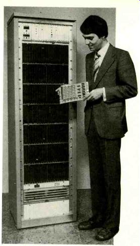
Fig. 4. A 1978 digital television field store on one board. The rack
is a 1973 field store.
DIGITAL STANDARDS CONVERTERS
Replacement line-store converters. The development of new digital integrated circuits with sufficient speed for video signal processing opened the door to the development of digital line-store converters’. At this stage it was clear that the UK 405-line service was going to be maintained for a considerable further period. In view of this, the replacement of the analog line-store converters by more stable and reliable digital equivalents was easy to justify. Moreover, the very high signal quality and immunity to distortion of digital implementation brought with it the possibility of using more contributions and a wider range of coefficients in the interpolation process. This held out the possibility of significantly improved interpolation.
The two fundamental numerical properties of a binary pulse code modulation system are the sampling or clock frequency and the number of binary digits (bits) used to describe the value of each sample. For 625/50 PAL color signals, a sampling frequency of about three-times the subcarrier frequency was conventionally used (about 13.3MHz). However, for 625-to-405-line conversion it was possible to reduce the sampling frequency because of the relatively restricted upper frequency limit of the 405-line system. This, coupled with the necessity of removing the color subcarrier and most of its significant sidebands, allowed the use of 729-times line frequency sampling (approximately 11.4MHz).
The number of bits used in a digital system must be sufficiently large to ensure that no visible 'contours' occur when an area of almost uniform brightness is being scanned. In common with other broadcast quality television signals, 8-bit digital signals were used for the conversions between analog and digital signals at the input and output. Also, somewhat greater precision was used internally at critical stages to avoid a build-up of quantizing distortion.
Apart from the input and output conversions, the main processes in a digital standards converter are digital signal storage and digital arithmetic to allow the summation of weighted contributions from different lines.
The store units of the digital converters were based on digital shift registers. Reasonably low power consumption was achieved by using mos technology, in which the individual transistors only draw appreciable cur rent when changing state. Even so, the maximum operating frequency of these de vices (2MHz at that time) was insufficient to carry the input samples directly and it was necessary to de-multiplex the signals into six parallel paths to achieve the necessary operating rate. Thus six 100-element registers were a convenient means of providing the storage necessary for one television active-line period.
New lines are formed by combining weighted proportions of lines from adjacent positions in the field. In digital arithmetic, the multiplication process consists of repeatedly shifting the significance of the input sample value and adding the result to a total under the control of the individual bits of the multiplier coefficient. In early line-store converters, each multiplier was assembled as an array of binary adders and gates. The complexity of this array grew in proportion to both the number of bits per sample and the number of bits per coefficient. Thus, at first, the precision of the coefficient was limited to three bits, allowing coefficient values of one-eighth, two-eighths, etc. to be used. Another means of limiting the complexity of the arithmetic in the early experiments was to use linear interpolation. Be cause the coefficient values were always C and (1-C), a single multiplier could be used operating on the difference between two sample values. In later versions, as the level of integration in the digital circuits was increased, the limitations on both the number of coefficients and their precision were progressively removed.
Interpolation in the frequency domain. Until this point, the design of interpolation methods had been restricted by the small number of coefficient values available. The particular set of coefficients to be used was in general determined by approximating the geometrical position of the required line relative to its neighbors. A more theoretical approach was therefore required in order to make full use of the much larger numbers of coefficients available in a digital interpolator. This was provided by using a frequency-domain interpretation of interpolation'".
The interpolation process can be considered as equivalent to the processes of low-pass filtering, to return the signal to the form of a continuous image, followed by rescanning on the new standard. This concept is very similar to the mode of operation of the optical, image-transfer converters. In the frequency domain, the scanned signal consists of a series of spectral components, which repeat the baseband spectrum of the image at harmonics of the sampling frequency (the line and field frequencies). The interpolator, in its low-pass filtering role, then suppresses the spectral harmonics to leave the baseband spectrum. Resampling at the scanning rates of the output standard then introduces new harmonic spectra in different positions from those of the original standard.
With this spectrum-based interpretation of the standards conversion process, the signal impairments can be explained in terms of imperfect operation of the low-pass filter. If the filter fails to suppress the harmonics adequately, then the resampling process will repeat the spectra with some components falling into the low-frequency region. As these residual components will be incorrectly related to the original baseband spectrum of the output scanning standard, they will appear in the picture as patterns of the wrong frequency, an effect usually known as 'aliasing'. Alternatively, if the filter has adequate passband response, then some of the wanted baseband components will be lost, and the picture will have a soft or blurred appearance.
Field-rate conversions. Whereas digital implementation and the freedom to use more coefficients improved both the basic signal quality and the interpolation performance of the line-rate converters, the quality of the conversion was always limited by the lack of access to the lines of the adjacent fields. In an interlaced scan, the high-frequency vertical information is shared between adjacent fields. So, by restricting access to only one field, some wanted component frequencies were replaced by unwanted alias patterns.
Although, in principle, field storage could have been used, it was always judged that the benefit in performance was unlikely to justify the high cost involved. However, in field-store conversion, digital storage was used almost as soon as it became practicable, despite its high cost.
Cost was still a considerable constraint in the design of early digital field-store standards converters. As in the line-storage converters, mos shift registers were used as the storage elements, but in this case the larger 1024-element devices were suitable.
Even so, the enormous number of devices involved resulted in power dissipation difficulties. Since, in these devices, most of the power dissipation occurs as the charge is transferred from one stage to the next, it was advantageous to clock the registers more slowly when access to the stored lines was not required. Unfortunately, the registers could not be stopped altogether, because the charge would leak away over a prolonged period and this led to the added complication of correct phasing of the data in the registers when the time came for them to be read-out.
This involved marking the start of the stored data with a code.
As well as complicating the store operation of early digital field-store converters, the high storage cost resulted in completely different modes of operation in the two directions of conversion. This also resulted, in part, from the converter initially being designed only for one direction of conversion, from 525/60 to 625/50. In this direction, two fields of the incoming signal were stored directly, still in composite NTSC form. This approach reduces the storage requirement in two ways: first, the 525-line standard has fewer lines and, secondly, storing the NTSC color signal avoids the extra capacity necessary for separate Y,U and V signals. However, separate decoders were needed at the outputs of the two field stores to convert the stored NTSC signals to multiplexed YIQ form for interpolation. This was followed first by movement interpolation, to produce a 525/50 signal, and then line interpolation, to produce a 626/50 signal, with a conventional analog PAL coder at the output.
Conversion from 625/50 to 525/60, which was added later, was constrained to use the same two field-stores, again in 525-line NTSC form. The PAL or SECAM 625-line input signal was first decoded and digitized to form a multiplexed YIQ signal. Line interpolation was then used to produce 525/50 signals which were digitally coded in NTSC form for storage. After leaving the field stores, the signals were decoded again to multiplexed YIQ form for conversion to 525/60 by the movement interpolator, be fore finally being encoded once again as NTSC.
In addition to the improved signal quality through using digital storage, the interpolation performance was significantly better than for either the optical or electronic analog converters. Line interpolation was very similar to the methods used in the earlier line-rate converters although, be cause the movement and line interpolation were carried out as separate processes, it was only possible to use vertical detail from one field, thus limiting the resolution. The field-rate conversion process was visualized in terms of the displacement of the input fields from their correct positions in time. To counteract this displacement, the movement interpolator used an approximation to linear interpolation, so that proportions of the adjacent fields were used, weighted according to their proximity to the required position. The complication of the multi pliers was still limited by cost considerations.
Subsequently, the costs of digital storage and arithmetic fell dramatically and a number of relatively low-cost digital field store synchronizers were developed. As storage was still the main cost, however, it was possible to add extra circuitry for features such as noise reduction, based on recursive temporal filtering, and special effects. The combination of these extra circuits provided the basic requirements for field-rate standards conversion, although the recursive temporal filtering tended to limit the performance of the movement interpolation. This was primarily the result of the asymmetrical impulse response of the recursive filter which tended to leave a trail of multiple images following moving objects, reminiscent of optical con version methods. In some cases, movement detectors were added to change the filtering between 'still' and 'movement' modes.
However, such converters were always prone to choosing the wrong mode because of the difficulty of detecting movement reliably over a wide range of signal conditions.
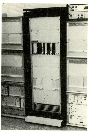
Fig.5. Rack of instrumentation for studying interpolation apertures.
Eventually, the constraints on interpolation were removed by the falling cost of random-access memories (rams) and the reduced complexity of making multipliers of full accuracy. In particular, the use of rams greatly simplified the provision of multiple outputs from the field stores. thereby removing the need for separate line stores for line interpolation23'24. Simultaneous access to four lines from each field was provided by arranging the field stores as four quarter-field blocks, each with its own output. The writing of successive items into different quarters then ensured that four consecutive lines were always available at the outputs. A consequence of this store organization was that it placed a limitation on the maximum size of ram device that could be used. Thus, 4096-by-1 rams could be used, whereas the later 16384-by-1 devices could not, because the minimum store block became too large and could not provide sufficient access points.
It also became possible to combine movement interpolation and line interpolation into a single process, so that lines of the output standard were synthesized directly from an array of stored input lines. This had the advantage that more use could be made of vertical detail carried in the two fields of an interlaced picture, without degrading movement performance.
Experiments showed that simultaneous access to four lines from each of four input fields gave useful improvements in interpolation performance over the use of fewer contributions. However, with such a large number of contributions, it was no longer feasible to visualize the movement interpolation process in terms of positional displacement. Because of this, the frequency-domain understanding of interpolation, applied successfully to the line interpolation process in the line-rate converters, was broadened to cover the movement interpolation process as well.
In this case, because of the two dimensional (vertical-temporal) nature of television scanning, it was necessary to define a two-dimensional interpolation aperture function to control the choice of the coefficient values used to weight the input lines. This function then defined the vertical-temporal low-pass filtering action of the interpolator, used to suppress the unwanted scanning products of the original scanning process. The size of the aperture determined the spacing at which the frequency characteristic could be defined. By setting the required frequency response values at this predetermined spacing, the associated aperture function could be calculated by two-dimensional Fourier transformation. Initially, the relative importance of retaining or suppressing parts of the spectrum was not known, but the apertures were optimized by comparing the performances of different apertures using a versatile experimental standards converter. With these techniques, further improvements in the conversion quality were made, virtually eliminating impairments to still pictures and substantially reducing those on movement. Nevertheless, some residual movement judder effects remained, which became particularly noticeable on moderately fast camera panning.
In practical terms, this later generation of digital field-store converters benefitted from a rationalization of the organization of earlier converters. Thus, the converters were truly reversible, having the same organization in both directions of con version. Cheaper storage allowed the signals to remain as multiplexed digital YUV components throughout, so that the storage and interpolation processes were common to luminance and color interpolation. Because of the relative bandwidth requirements of the luminance and color components, the input standard video was stored as an interleaved sequence of five words YUYVY. At the multiplexed data rate of 16MHz, this provided sufficient samples for bandwidths of 4.2MHz for luminance and 1.3MHz for each color difference signal. However, a further feature of this converter was the use of different interpolation apertures for the luminance and color difference signals. This required the multiplier coefficients to change at sample rate rather than line rate, but allowed the interpolator to re duce the vertical and temporal bandwidths' of the converted chrominance signals, thus suppressing un wanted noise and cross-color components left by the input standard color decoder26.
Fig.6. Split-screen picture with two apertures. Apertures 10 (left half)
gives vertical aliasing visible in the diagonals, while aperture 27 virtually
eliminates the aliasing.
FUTURE DEVELOPMENTS
The full potential of the frequency-domain approach has been exploited by the present generation of converters, but their performance is limited by aliasing built into the input signal. This is present because the camera integration process fails to filter temporal frequencies in the signal to within the Nyquist bandwidth. Because of the resulting overlap of true and aliased frequencies, it is impossible to separate the two.
Experimental work on high-definition television (h.d.t.v) has produced a promising new approach to the standards conversion problem27. This uses a technique known as movement compensation to overcome most of the residual judder effects of standards conversion. When the motion of an object from field to field is reasonably predictable, such as during camera panning, the probable position of the object during an arbitrarily-timed output field can be calculated. Whereas a conventional interpolator would just combine the input fields in weighted proportions, the movement compensator would alter the positions of the moving object to match the required output position and then interpolate. Thus, pro vided that the boundary of the moving object could be identified accurately, judder would could be identified accurately, judder would be eliminated. Less predictable movements, however, such as the leg movements of a galloping horse, could riot be accommodated.
The development of standards converters over a considerable period of time has been the result of successive improvements, both in the technologies used and in the supporting theories. Each change of technology, first from optical to electronic analog and then from analog to digital, has been accompanied by the need for new ways of visualizing the conversion methods to obtain a better understanding of the processes involved. In particular, the alternative approaches of viewing conversion either in the time domain or the frequency domain have now almost come full-circle, with the time-domain method of movement compensation perhaps about to take over from frequency-domain methods.
ACKNOWLEDGEMENTS
Many individual engineers and many enterprises deserve credit for the evolution of television standards converters. However, it is felt that it would be invidious to name individual engineers or enterprises in this paper. Nevertheless, the list of authors in the reference does give a fair indication of the key innovators in the field.
The permission of the BBC Director of Engineering to publish this paper is gratefully acknowledged.
References
1. Lord, A.V., 1953. "Conversion of television standards”. BBC Quarterly, Vol. VIII, No. 2, Summer 1953.
2. Lord, A.V. and Rout, E.R., 1964. "A review of television standards conversion". BBC Engineering Monograph, No. 55, December 1964.
3. Jones, A.H., Lent, S.J. and Reed, C.R.G., 1964. "Image-transfer standards conversion: modulation due to a difference between field frequencies". BBC Research Department Report No. T-130 (1964/9), July 1964.
4. Dillenburger, W., 1971. "Problems of electro-optical color standards converters". Radio Mentor ( Germany), Vol. 37, 3, 1971.
5. Lord, A.V. and Rout, E.R., 1962. "An outline of synchronous standards conversion using a delay-line interpolator". BBC Research Department Report No. T-096 (1962/31), July 1962.
6. Jones, A.H., 1964. "Line-store standards conversion: the subjective determination of the necessary number of stores". BBC Research Department Report No. T-123 (1964/13), February 1964.
7. Devereux V.G., 1963. "Line-store standards conversion: the subjective effect of certain switch and store imperfections". BBC Research Department Report No. T-120 (1963/64). December 1963.
8. Rainger, P., 1962. "An. o system of standards conversion". Report of the International Television Conference, London, 31st. May-7th June, 1962. IEE Conf. Rep. No. 5, IEE London, 1963, pp. 170-172.
9. Rainger, p. and Rout, E.R., 1966, "Television standards converters using a line store". Proc. IEE. 1966, Vol. 113, 9, pp. 1437-1456.
10. Jones, A.H., 1965. "Line-store standards conversion: the design of video transmission lines". BBC Research Department Report No. T-150 (1965/35), November 1965.
11. Brocklesby, C.F., Palfreeman, J. and Gibson, R.W. (of Mullard Limited), 1963. "Ultrasonic delay lines", Hiffe, London, 1963.
12. Wharton, W. and Davies, R.E., 1966. "Field-store standards conversion: conversion between television signals with different field frequencies using ultrasonic delays". BBC Research Department Report No. T-164 (1966/12), March 1966.
13. Harvey. R.V., 1971. "Field-store standards conversion: equalizers for ultrasonic quartz delay lines". BBC Research Department Report No. 1971/36, October 1971.
14. Dalton, C.J., 1968. "The performance and specification of ultrasonic delay-lines for use in television broadcasting". BBC Research Department Report No. EL-13 (1968/3), February 1968.
15. Mortimore, M.J. and Le Courteur, G.M., 1970. "A method of averaging frequency modulated signals". BBC Research Department Report No. 1970/14, April 1970.
16. Edwardson, S.M., 1968. "An advanced form of field-store standards converter". International Broadcast ing Convention 1968 (IBC 68), 1EE Conf, Pub. No. 46, Part 1, September 1968.
17. Davies, R.E., Edwardson, S.M. and Harvey, R.V., 1971. "Electronic field-store standards converter". PROC. IEE, Vol.118, No. 3/4, March/April 1971.
18. Walker, R., 1971. "Digital line-store standards con version: a feasibility study". BBC Research Department Report No. 1971/44, November 1971.
19. Drewery, J.O., Chew, J.R. and Le Couteur, G.M., 1972. "Digital line-store standards conversion: pre liminary interpolation study". BBC Research Department Report No. 1972/28, August 1972.
20. Le Couteur, G.M., 1973. "Digital line-store standards conversion: determination of the optimum interpolation aperture function". BBC Research Department Report No.1973/23, October 1973.
21. Baldwin, J.L.E., Stalley, A.D., Coffey, JA, Greenfield, R.L., Lever, I.R. and Taylor, J.H., 1974 "DICE: The first intercontinental digital standards converter". Royal Television Society Journal, September/October 1974.
22. Baldwin, J.L.E., Lever, I.R., Connolly, W.P., Corbyn, T.E., Greenfield, R.L., Thirlwall, A.C., Barrett, K.H., Taylor, J.H., Bellis, A., Carmen, P.R., Dunne, J.F., lye, J.G. and Wilkinson, J.H., 1976. "Digital video processing-DICE". IBA Technical Review. No. 8, September 1976.
23. Clarke, C.K.P. and Roe, G.D., 1978. "Developments in standards conversion". IBC 1978, IEE Conf. Pub. No. 166, September 1978.
24. Astle, J.M. and Shelton, W.T., 1980. "Digital television standards converter with random access memory storing four fields." IBC 1980, IEE Conf. Pub. No. 191, September 1980.
25. Clarke, C.K.P. and Tanton, N.E., 1984. "Digital standards conversion: interpolation theory and aperture synthesis". BBC Research Department Report No. 1984/20, December 1984.
26. Clarke, C.K.P., 1982. "Digital standards conversion: comparison of color decoding methods." BBC Re search Department Report No. 1982/6, June 1982.
27. Tanaka, Y., Ohnura, T., Okada, K., Ohtsuka, Y., Kurita, T., Goshi, S., Ninomiya, Y. and Nishizawa, T., 1986. "HDTV-PAL standards converter". NHK Laboratories Note No.326, January 1986.
------------
Also see: Electrometer amplifiers for sub-pico-amp currents
==========
(adapted from: Wireless World , Jan. 1987)