AMAZON multi-meters discounts AMAZON oscilloscope discounts
Electronic organs have become big business and are found frequently in a goodly percentage of homes. A small electronic organ can produce sounds that at one time could be generated only by conventional organs many times the size and price. Tubes were used initially in electronic organs, but in recent years the transistor has taken over. Transistorized circuits are tiny and take up a small percentage of space.
Different manufacturers use radically different physical and electronic designs. It is not the purpose of this discussion to cover the field, but to explore a typical organ circuit and the means to test and align it.
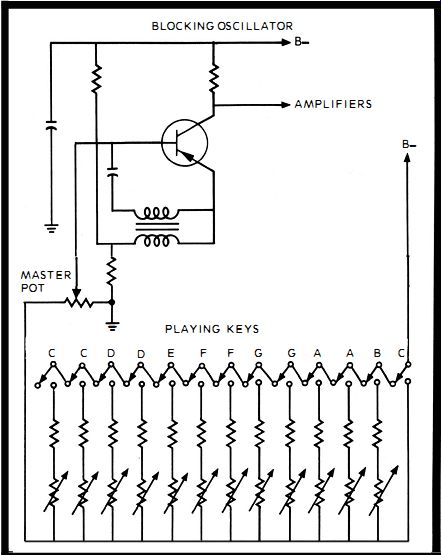
Oscillator: All organ circuits are based around an oscillator. The oscillator reproduces electronically the sound of reeds or strings in non-electronic musical instruments. The electronic organ oscillator, in addition to its fundamental frequency, also generates many harmonics. These harmonics are desirable in order for the organ to simulate mechanical musical instruments. The typical electronic organ uses one transistor in a blocking oscillator circuit configuration (Fig. 96). In the oscillator base circuit are twelve sets of series resistors. Each set of resistors is designed to make the oscillator run at a frequency corresponding to the twelve keys in an octave.
Large keyboard organs have a separate oscillator for each octave, or use the same oscillator and simply have more series resistor sets for the additional keys. Each resistor set can have one fixed resistor and one potentiometer. The pot is used for accurate tune-up.
The playing keys are actually specially designed switches. As the key is depressed, it closes the circuit on one of the series se t of resistors. A spring on the key pushes it back open as the hand pressure on it is relieved. The oscillator transistor is biased off by returning the base through a master potentiometer to the chassis ground. As a key is pressed, the set of series resistors is shunted across the master pot and the resultant change in bias turns on the transistor. The oscillator starts and produces the called for tone. Releasing the key places the master pot back into the circuit, reverse bias is developed and the oscillator quits. When another key is depressed, the same sequence occurs, except that another oscillator frequency is generated and thus another note.

Fig. 96. A typical organ circuit is a simple blocking oscillator. The playing
keys vary the base bias as they are pressed.

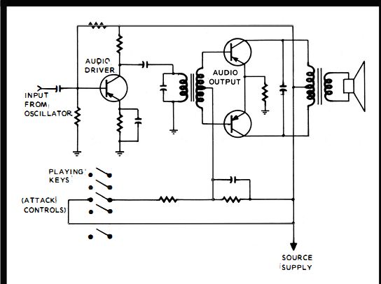
Fig. 97. Attack controls are attached to the playing keys and control a simple
pushpull amplifier.
Amplifier : After the note is generated, it must be amplified and fed to a speaker system. For pleasant music to be heard, the notes should blend together instead of turning on and off quickly, producing a staccato effect. The blending of the notes is called the "attack" and an attack type amplifier must be used.
The attack amplifier (Fig. 97), also has to be turned on and off with each key. The switch for the amplifier is attached in such a way that it does not shut off simultaneously with the oscillator switch but slightly afterwards. That way the attack effect is helped along. An attack amplifier looks quite like any audio amplifier. Typically, it can be a push-pull type. The input from the oscillator is fed to a driver transistor. The output of the driver is sent to the primary of a push-pull type transformer. Both ends of the transformer are attached directly to the bases of the twin transistors. The center tap of the transformer passes through an RC network to the attack control switches. There is one switch for each note, which is closed when the musician depresses a key. The key closes the oscillator and amplifier together. The time constant of the RC network determines the amount of attack.
The push-pull transistors are biased off until the attack switch is closed. Then they turn on and stay on until the switch is reopened and the RC network permits the bias to gradually become reversed and turn off the transistors. The speaker system is carefully designed for the organ. When you replace a speaker, it's best to use an identical unit.
Many of the speakers are inexpensive and the tendency during replacement is to use a better, more expensive speaker. Should you do that and the better speaker sounds bad, it's because the less expensive speaker was designed for that organ. You have upset the delicate tonal qualities with the better speaker. Before doing anything else, try the correct speaker. It probably will prove better.
No. 148: ORGAN TUNE UP
As an organ ages, the electronic components age, and instead of a pure note emanating from the speaker, the note is out of tune. Each note can be tuned by a variable resistor. Changing the setting of the resistor changes the oscillator frequency slightly and sets the note that is heard (Fig. 96), The manufacturer's service notes will pinpoint the location of each variable resistor. They can be set by an experienced musician for exact tone. Some of the service notes provide procedures for the average organ owner to tune his own organ .
No. 149: WHEN ONE NOTE DOESN'T WORK
If you are playing the organ and discover that one of the notes is inoperative, locate the oscillator circuit. In the oscillator there are as previously described a separate series 2-resistor setup for each note. One resistor is fixed and the other is variable. Also in that specific circuit leg is the switch attached to the playing key. They are the three suspects that can cause the loss of the one note. Test them one at a time. Replace the bad component with an exact replacement. Then retune the note for the correct tone.
No. 150: TESTING A CIRCUIT WITHOUT SERVICE NOTES

Fig. 98. A scope ca n be used to trace through the organ circuitry, since
it only has to follow the oscillator signal.
Electronic organs, like any other electronic gear, are easier to troubleshoot if you have the manufacturer's service manual. However, unlike most consumer type gear, organs can also be easily tested without the service notes. That's because the circuitry in an organ is repeated over and over and over again.
When a particular circuit seems to not be working properly, while other circuits just like it are, try this : Make a sketch of the circuit, then with the aid of an identical circuit that is operating, take voltage readings at test points like transistor junctions. Then, compare the voltages you've obtained at the known good test points, with what is present at the defective circuit test points. By comparing the two sets of readings, you can quickly obtain voltage clues.
No. 151: SIGNAL TRACING ORGAN CIRCUITS
When a complete keyboard quits, the oscilloscope is very useful. All the signals generated and passed through the circuits are in the audio range. Using a scope with internal horizontal sweep, the vertical input will display what's going on inside the circuit.
The first test point to check is the output of the oscillator (Fig. 98 ). One of two displays will be seen. One is the audio signal developed by the oscillator. If it is present at the oscillator output the oscillator is cleared as the troublemaker. The amplifier is indicated next. Should there be no oscillator output, the oscillator is defective, and you can find the reason by checking back into the circuit.
A typical oscillator output uses an emitter-follower circuit to deliver the signal to the amplifier. At the emitter output test point, the fundamental frequency can be picked off. When the fundamental is not present, the next test point is the collector of the preceding transistor amplifier. If the signal is displayed at that point, the emitter-follower circuit is suspect. Should the frequency still not appear, the base of the amplifier is the next logical test point. The same rules apply. No display clears the amplifier. A good display at the base indicates a defective amplifier circuit.
No. 152: TESTING THE OSCILLATOR FREQUENCY
When there is still no display, it could mean trouble in the oscillator frequency divider which contains a number of resistors, capacitors and a switch. The scope probe is touched on the collector of the oscillator. If a signal is present, the oscillator is running.
The oscillator frequency itself can be confusing. Some organs use an oscillator that runs at the fundamental frequency which involves a low bass note at about 250 Hz. When the scope is attached to the collector and the lowest key is held down, a 250-Hz signal would be displayed. 'However, in other organs the oscillator runs at multiples of the fundamental frequency ; for instance, six times the fundamental, which in this case would be 1500 Hz. On these organs the scope should display the 1500-Hz frequency when the lowest note key is held down. If no display is produced during the time a key is held down, the oscillator is not running and the oscillator circuit should be examined by voltage and resistance tests.
No. 153 : TESTING DIVIDER CIRCUITS
For these tests you should have the schematic of the organ. As mentioned previously, some organs use an oscillator running at multiples of the fundamental frequency; for instance, 6f or six times the fundamental. When there is a 6f oscillator, in order to end up with the fundamental frequency f, there must be divider circuits in the organ.
The reason for the multiplier oscillator and then the divider circuits is so the organ can generate strong second and third harmonics, which when mixed with the fundamental produces realistic musical instrument imitations. All types of circuits are found in actual use. The schematic of the individual organ provides the actual functions. The scope tells all. Set the horizontal internal sweep for the fundamental as produced in the emitter follower. Then touch down on the divider circuits ; the binary divider divides the oscillator frequency by two. If the oscillator is 6f, the output of the binary divider should display 3f. The scope display should show three sets of fundamentals as the internal sweep runs at the fundamental. A ternary divider circuit divides the oscillator by three. This makes the 6f into 2f.
Therefore, the output of any ternary divider should display two sets of fundamentals on the scope .

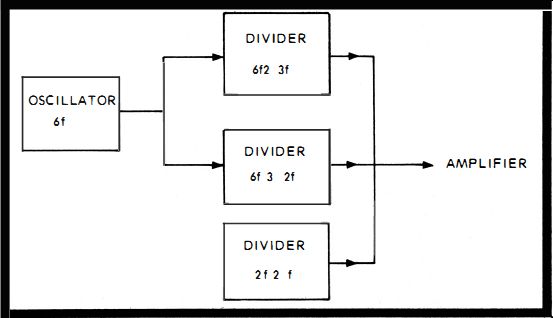
Fig. 99. Frequency divider circuits are used to produce the various harmonic
tones needed for music.
No. 154 : BLOCK DIAGRAM SIGNAL TRACING
Working your way through fundamental, binary, ternary divider and multiplier circuits can be a confusing experience.
But most of the confusion can be eliminated if, once you discover it is necessary to ascertain the actual output frequency numbers, multiples and divisions, you quickly draw a block diagram similar to that in Fig. 99. For instance, suppose you see from the schematic that there are three outputs from an initial 6f oscillator. The three outputs are f, 2f and 3f.
Then you see that the f is finally produced by first dividing the 6f by three in a ternary divider, which produces 2f. Then the 2f is made into f by passing the 2f through a binary divider.
Meanwhile, the 2f from the ternary is utilized as another direct output. Then, finally, you analyze that the 3f is obtained individually by-passing the 6f through another binary divider. Even though the mathematics is elementary, confusion can result from the maze. A block diagram reduces the confusion and guides you to the correct analysis.
No. 155: SIGNAL INJECTION TESTS
While scope signal tracing is an adequate technique, an alternate procedure, equally as good for localizing trouble, is signal injection. With an audio generator tuned to a note about or under 1 kHz, inject ions can be made. The best place to start is the center point between the amplifier and the oscillator circuit output. The speaker will provide the output. if the injection produces a good tone, the amplifier and speaker outputs are good and the oscillator area is suspect. When the injection produces no tone, the oscillator, by elimination, is cleared and the amplifier and speaker circuits are suspect.
The indicated trouble area can be further narrowed down by starting at the center. A test signal should be injected at the appropriate test points one at a time such as the base and collector or control grid and plate. When injecting a signal through the amplifier, as soon as a note is heard, the defective circuit has just been passed over.

Fig. 100. A binary frequency divider changes the oscillator output to one
ha lf of its opera ting frequency.
No. 156 : FINDING SOURCE OF OSCILLATION
The binary and ternary divider circuits are usually designed in such a way that they resemble a multivibrator circuit (Fig. 100). The main difference between them and such an oscillator is the bias on the transistors. On occasion, the bias will be lowered and the stages, when energized, go into oscillation.
When the organ starts making noises, suspect these stages immediately and test the bias. Chances are good you'll find the bias has decreased and is sending the stage into oscillation.
No. 157 : INCORRECT MUSICAL NOTES-NOT ENOUGH BIAS ON DIVIDER CIRCUITS
This is a companion to the above trouble. Too little bias, instead of causing the stage to oscillate, causes the stage to not do any dividing. Instead of amplifying the 6f output from the oscillator, the divider stage is triggered into oscillation and it produces an output frequency of 6f. Then when it mixes with the other two outputs, the resultant frequency is all wrong.
No. 158: INCORRECT MUSICA L NOTES-TOO MUCH BIAS ON DIVIDER CIRCUITS
Following along the same line of reasoning, too much bias on the ternary divider turns off the stage. Since this stage in this circuit configuration produces the fundamental as well as 2f, they both will be missing. Only 3f is produced with the resultant incorrect sounding music. Incorrect bias on the stages, when suspected by the symptoms, is easily localized by signal injection or signal tracing and then pinpointed by voltage and resistance tests.
Organs are quite simple mechanisms in comparison to home electronic equipment such as color TV. If you are an organ owner, then in addition to the electronic understanding, even more symptoms will be obvious to you, during testing, from the sound of your instrument. With long use of an organ, you can almost tell what has gone wrong from the sound of it.