AMAZON multi-meters discounts AMAZON oscilloscope discounts
INTRODUCTION
Up to this point all the drawings and diagrams discussed have primarily shown the functional or electrical relationship between parts and components. The physical relationship is also important in an electronic or electrical drawing. This type of drawing is called the wiring diagram and, as its name implies, is a diagram that aids in the assembly or production of the entire electronic package.
WIRE
The correct drawing or representation of wire is critical. There is not just one type of wire used for all assemblies. There are many different sizes, styles, and types of wire and many methods of wiring. Wire is made of material like copper or aluminum that will allow current to flow through it with very little resistance. Since the primary purpose of wire is to connect two points together, it should not alter the overall electrical characteristics or function of the circuit.
Connecting wire is generally either a single strand of wire or several strands fixed together as one wire. This wire can be insulated or covered with a material like nylon, enamel, polyester, rubber, or other material that does not conduct electricity very well. The size, or cross-sectional area, of wire can vary. In addition, the size of the insulating material on the wire can vary. The insulating material can be made in many different colors to aid the technician in identifying the wire and its function.
All this information must be included on any wiring diagram, since the diagram is often used as the assembly or production drawing. This drawing may be included in a service or instruction manual, and without identification of color and type or size of wire, it would be very difficult for the technician to trace the circuit paths or repair the equipment.
Wire Gauge
The size of the wire is called the gauge. Wires come in standard sizes identified by whole numbers, which have been set by the American Wire Gauge (AWG) Standards. The smaller the number, the larger the wire is. For a complete list of available wire sizes, search Google for "American Wire Gauge".
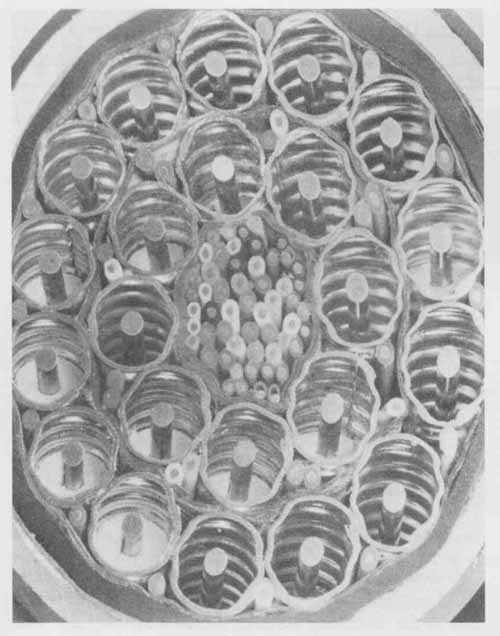
FIG. 1 Bundle of large-size wires surrounded by coaxial cable. (Courtesy
of Western Electric Co.)
Wire ranges in size from about as fine as a piece of hair to as big around as a small finger, as shown in FIG. 1. All different sizes have specific uses, and each size has different electrical characteristics in terms of how much resistance there is in the wire or how much current can safely flow through it. Wire formed from many strands of wire is not gauged in the same manner as solid wire; however, stranded wire does have similar electrical characteristics and limits. The biggest advantage of stranded wire is that it is more flexible than solid wire and should be used where the wire is likely to be moved or when vibrations can occur. The primary disadvantage is that stranded wire with the same overall cross-sectional area as solid wire can only handle about 60% of the current that solid wire can handle.
To find the equivalent solid size of stranded wire, multiply the number of strands times the cross-sectional area of each individual strand. The total cross-sectional area corresponds to an AWG equivalent size for the stranded wire on the AWG chart of solid wire. Stranded wire, however, is normally identified by the actual strand, not by the equivalent solid wire. It is identified first by the number of strands and then by the AWG number of the individual strands. The numbers are separated by a slash. For example, 8/34 means a wire made up of 8 strands of #34 wire. Since the cross-sectional area of #34 wire is 39 circular mils, this wire is equivalent to approximately AWG #25 solid wire (8 X 39 = 312 circular mils). Remember that although these strands have approximately the same gauge or physical size as solid wire the maximum amount of current must be derated to about 60%.
Insulation
Many different types of materials are used to insulate conductors. The insulating material is necessary to provide protection to people and to make certain the wires do not make contact with other wires or the metal cases. Any time two conductors touch, an electrical connection is made. If a wire is to be used to connect two components, then it may only touch the leads of those two components. It is physically impossible to keep a long loose wire from making contact with anything else, so insulation is used to cover the length of the wire. Only the ends are exposed so that they may make contact.
Different materials have different insulating properties; therefore, the type of insulation is determined by the particular application. Insulating materials come in a number of different solid colors or in a solid color with one or two stripes of different colors, called tracers. The colors aid in tracing circuit connections of equipment, as well as in fabricating a system.
Method of Termination
A wiring diagram has three main labels: the size and type of wire; the size, type, and color of the insulation; and the type of connection to be made. AU connecting wires will end either in bare wire that must be soldered or in terminals, clips, jacks, plugs, or other mechanical means of making connections. All this information must be included on the wiring diagram. The choice between soldering or using some other form of connection is determined by how often the connection might need to be removed, either for repair or for multiple use of the equipment. Equipment with interchangeable sections does not have soldered interconnections. A sliding con tact or quick-disconnect, plug-type assembly is used in stead.
PARTS OF A WIRING DIAGRAM
All wiring diagrams must include at least the components, the connection lines, and the means of connection. The components are frequently represented by a geometric shape showing physical characteristics, as in FIG. 2, rather than the unique symbols used for electrical characteristics. The connection lines may be represented in a number of different methods (covered in detail later in this Section). The method of termination is designated by either a pictorial representation of the connector or simply a note identifying the type of terminals.
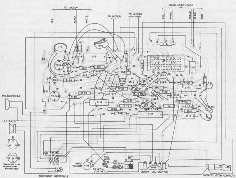
FIG. 2 Geometric shapes showing components in wiring diagrams. (Courtesy
of International Business Machines Corporation)
As with all other diagrams, the wiring diagram starts with a rough sketch. The circuit is divided into smaller sections based on the manner in which it will be assembled. For very simple circuits this may include just one main assembly.
The rough sketch establishes the initial space requirements for the final drawing, as shown in FIG. 3. All components are represented by their physical characteristics. Even though there is no proper size for these components, guidelines need to be followed. If the wiring diagram will be used in production or assembly, the picture must help locate the actual part. Components are frequently represented larger than life on the sketch. The size of each pictorial representation must show the location of parts and some proportional relationships to adjacent components.
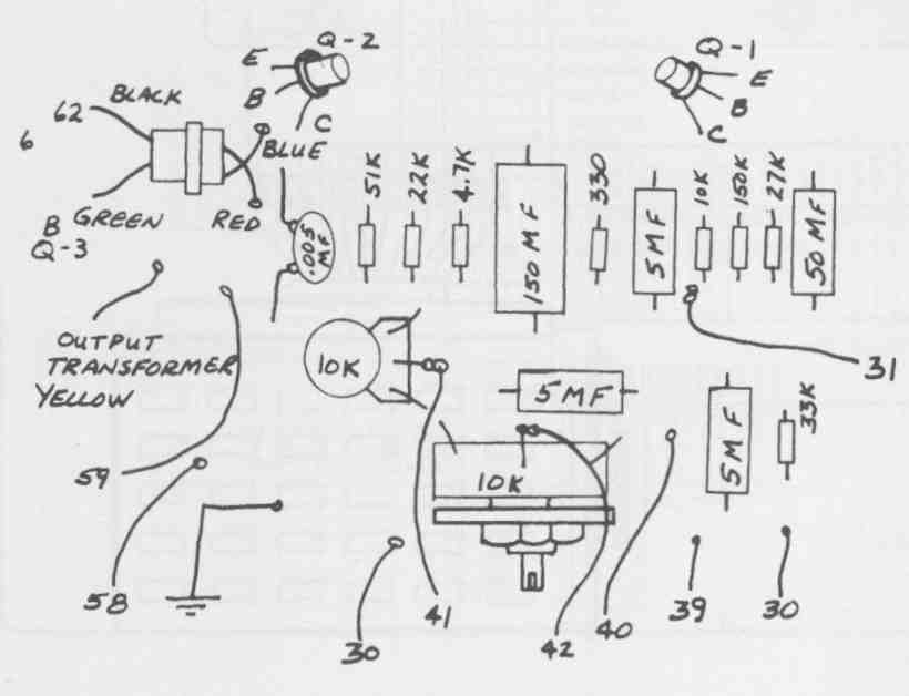
FIG. 3 Rough sketch establishing preliminary space requirements.

FIG. 4 Component outlines, identifying all tabs, slots, and spacing.

FIG. 5 Bottom view of chassis indicating all wiring. (Used with permission
from Radio Shack, a division of Tandy Corporation, Fort Worth, TX 76102)
For components with multiple leads, any identifying characteristics—such as tabs, slots, and polarity—must be shown on the drawing to ensure proper connections, as in FIG. 4. The pictorial representations are usually not pictorials in the sense of showing entire physical characteristics with multi-views or other pictorial methods, but are simply outlines best showing the required mounting space. If all the information cannot be shown in one view, then additional views may be required for final assembly. In many instances a single view of the bottom or actual wiring side of a chassis is sufficient to represent all components and their interconnections, as shown in FIG. 5.
Unfortunately, like all other electronic or electrical diagrams, there is no easy way to achieve a well-designed, well-balanced, and well-presented wiring diagram. The trial-and-error method must be used to achieve the final drawing. With practice and experience, fewer trials with fewer errors should be possible.
TYPES OF DIAGRAMS
According to ANSI there are three major categories for wiring diagrams: (1) continuous line, (2) interrupted line, and (3) tabular types.

FIG. 6 Point-to-point wiring diagram. (Courtesy of Motorola, Inc., Semiconductor
Products Sector)
Continuous Line
The continuous line diagram shows all connections and the location or travel of the wire from one point to another. This diagram is convenient for simple circuits not containing an excessive number of parts, where the actual assembly can be done one wire at a time. This type of drawing, illustrated in FIG. 6, has also been called a point-to-point connection diagram because it shows the drawing with the most specific details as it uses an individual line for every wire. As the circuit becomes more complex, this type of diagram can get very confusing. Showing every wire can be either a disadvantage or an advantage, depending on how many wires there are. The advantage is that it allows direct tracing of every circuit path and every component connection. The disadvantage is that too many paths are difficult to trace and may lead to mistakes or wrong connections. A trial sketch may be a good point-to- point sketch to get an idea of the overall needs of the finished drawing.
Another continuous line diagram is a modified point-to-point diagram. This diagram is frequently called a highway or trunkline diagram. If a group of wires flows through the circuit in the same direction, they can be represented by a single line, with each individual wire entering and leaving the main line, as shown in FIG. 7. As a wire enters or leaves the main trunk or highway, the connection is made by a short 45° diagonal line or a small ¼-in.-diameter circular arc, as seen in FIG. 8.
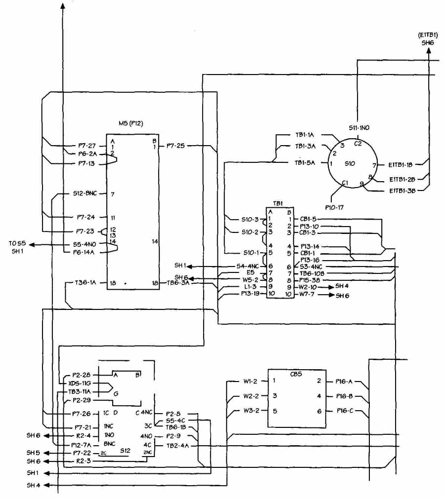
FIG. 7 Highway diagram with feeder lines joining main highway, forming short
45° lines. (Courtesy GTE Communication Systems Division)
Each wire entering or leaving must be identified by some type of code, as shown in FIG. 9, or the circuit paths cannot be traced. FIG. 10 is an example of this code, which identifies some or all of the following: wire number, size, type, and color; standard component designators; terminal numbers; harness number; origination; and destination. This code can be as simple as a number for every component in sequence, a number for all leads of the component, and a list of the destination by the component number, lead number, and color of wire.
When you draw a trial layout and many wires seem to go through the circuit in the same direction, you may decide that a highway diagram may be the most efficient method of preparing the final drawing. Keep in mind, however, that wires traveling through the assembly in approximately the same direction may not be bundled together or take exactly the same path. When a number of wires do, in fact, go through the circuit in the same direction, it may be advantageous to assemble the wires in precut lengths with the correct bends and terminations. You can then connect this group of wires as an assembly.
When a group of wires is assembled together in this manner, the assembly is called a harness. This is not the same as a cable. A cable is two or more wires or conductors insulated from each other and formed as a single unit. Cables are used when every installation is the same and when all the individual conductors originate and terminate in the same approximate location. (Harnesses and cables are covered in more detail later in this Section.)
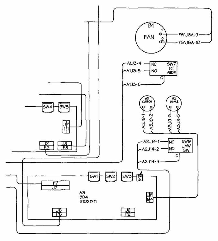
FIG. 8 Highway diagram with feeder lines joining main highway forming a small
1/4 in. arc.
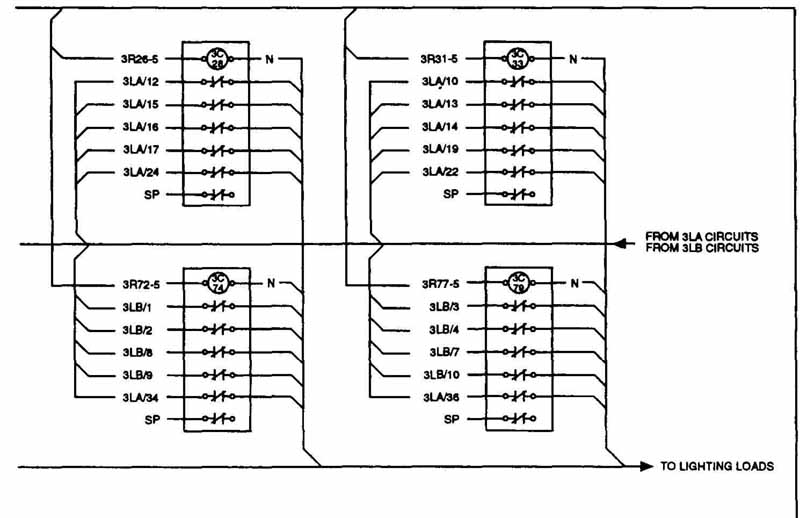
FIG. 9 Wire destinations for every connection. (Courtesy California Computer
Products, Inc.)
FIG. 10 Number code indicating every component in sequence, all leads, and destinations. (Courtesy GTE Communication Systems Division)
Interrupted Lines
Continuous line diagrams become impractical when circuits become too complex. An interrupted line diagram is used for complex wiring diagrams. This type of diagram is frequently called the baseline or airline method. In this method the placement of the lines may have very little to do with the actual routing of the wires. All wires go into one mainline, as shown in FIG. 11, no matter where they terminate or what path they take to get there.
This type of diagram may not be very convenient for production or assembly, since components are not drawn in their true physical relationships. It is, however, a means of presenting interconnections of many wires in a well-organized, easy-to-follow format. This type of diagram tells very clearly the organization and termination of every wire, although it does not show the exact path in which the wire travels. Diagrams of this type are very useful for service manuals and allow large, complex circuits to be drawn in a much smaller space.
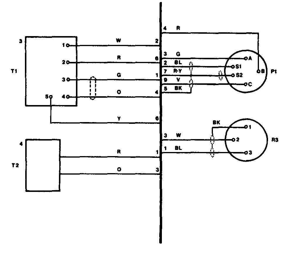
FIG. 11 Typical baseline diagram.
A baseline diagram consists of an imaginary main line located either vertically or horizontally. Short feeder lines run from the baseline to every terminal. These lines are drawn in the most direct path possible and terminate perpendicular to the baseline, as shown in FIG. 12. This diagram should be prepared with as few changes in direction as possible. When terminal markings are located in a circle and a direct line cannot be drawn to the baseline without passing through the component, all changes in direction must be formed at 900 angles, as in FIG. 13.
The baseline is usually represented as a heavyweight dark line, and the short feeder lines are normally medium-weight lines. The baseline can be located through the center of the drawing with the components divided and spaced on either side, or it can be located along any side (frequently the bottom) based on the type of circuit and number of components. As shown in FIG. 14, the baseline extends just past all feeder lines, far enough to avoid confusing it with the highway method, which at least implies the direction of wire routing. In more complex circuits, more than one baseline can be used. This allows a feeder line to enter one baseline and leave from a different one.
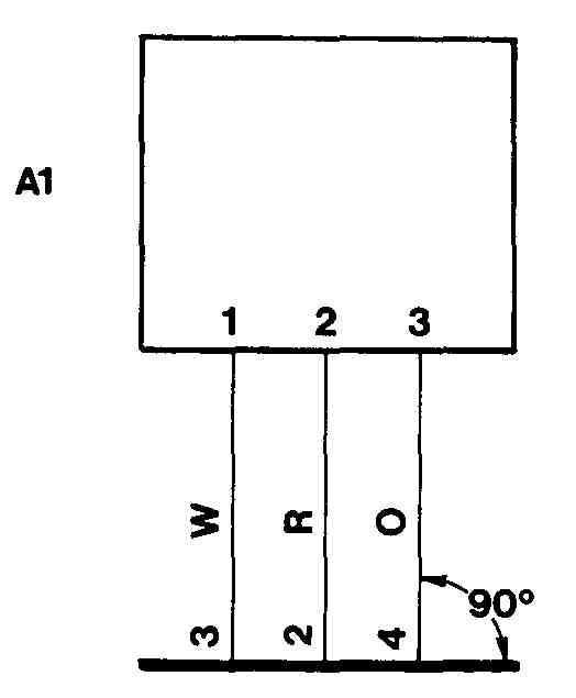
FIG. 12 Short feeder lines terminating perpendicular to the baseline.
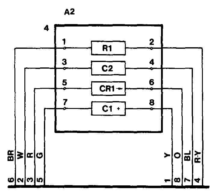
FIG. 13 Changes in direction at 90-degree angles.
Tabular Form
The third major classification of wiring diagrams is the tabular form. This form can be called a lineless diagram.
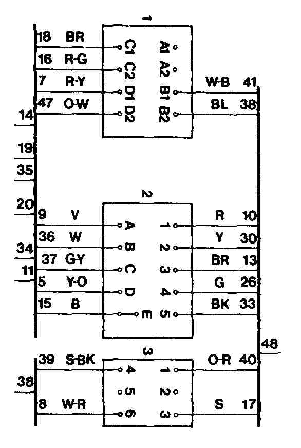
FIG. 14 Baselines extending just past last feeder line.
This type of presentation is the most incomplete visual representation of the interconnections, but it allows a large and complex diagram to be presented in a very limited amount of space. All connections are listed in tabular form, as shown in FIG. 15. This table should include some means of identifying each wire and should define the destination or endpoints. Like all other forms of identifying wires, a table can include the AWG number, color, type, and insulating material. It should definitely include the origin and destination points, as shown in FIG. 16.
CABLES AND HARNESSES
As stated earlier, a cable is a group of two or more insulated conductors confined in the same outer protection. Generally, all the conductors at either end terminate in the same approximate location. Frequently, a cable assembly terminates in a multiple connector. Typically, cable assemblies are used to connect one subassembly to another with mating connectors, as shown in FIG. 17. One common type of cable is the flat ribbon cable, where the conductors are side by side and the assembly looks like a flat ribbon. Although this type of cable is wide, it takes up very little routing space when used to interconnect subassemblies because it fits through a small slot between the assemblies. This can be seen in FIG. 18, where ribbon cables are used by Chrysler Corporation in the assembly of their travel computer.
When a group of wires is routed in the same direction, the wires can be tied together with a cord or other mechanical means, as in FIG. 19. This group of wires fs normally formed before the wires are connected to the circuit assembly. This large group of wires is called a harness, or wiring harness. Unlike the cable, there does not need to be any outside protective covering, or coating over all the wires. A wiring harness can have some type of clear coating to protect it against environ mental factors. In general, however, the primary difference between a cable and a harness is that the cable includes the protective outer covering, and a harness is simply a group of wires that for convenience have been bundled together. Also, harness wires can have many different lengths and can branch off at many different locations.
Both cable assemblies and harnesses need special attention and typically require individual drawings separate from the wiring or interconnection diagrams.
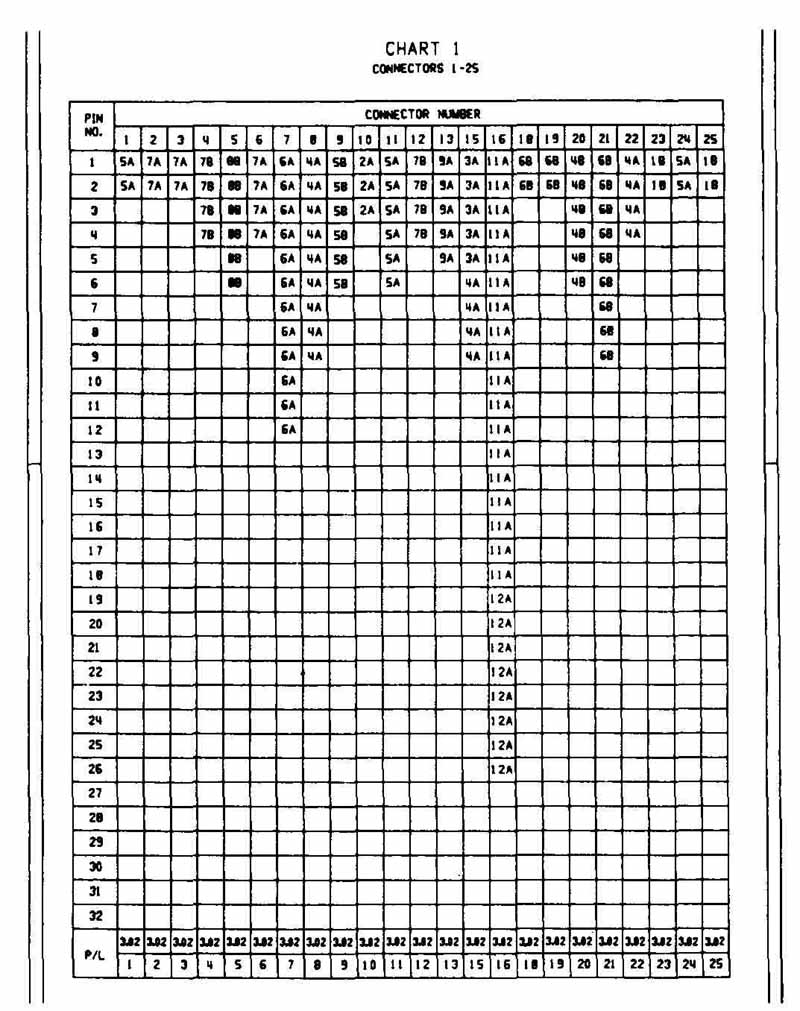
FIG. 15 Connections identified in tabular form. (International Business Machines
Corporation)
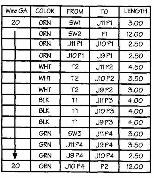
FIG. 16 Another tabular form method of showing connections.

FIG. 17 Wires connected with a mating connector. (Motorola, Inc., Semiconductor
Products Sector)

FIG. 18 Ribbon cable used in Chrysler’s travel computer. (Chrysler Corp.)
The preliminary step in preparing a harness diagram is to check the wiring diagram. If the wiring diagram is prepared on a highway-type drawing, the overall shape of the harness can be obtained directly from the wiring diagram. The highway diagram does show physical relationship, size, and location of all components. Usually, the harness diagram is prepared true size, whereas the wiring diagram or other electronic drawings are not. This makes sense because the harness diagram is frequently used to prepare the actual harness, and the wiring diagram is used only as a road map to trace circuit functions.
In the preparation of the actual harness, the entire assembly must be considered. Wires will not go through partitions unless holes are provided. When a harness must go through a hole, special strain relief or other protection is required. If the harness must travel around an unusually large component, the bend must be included in the preparation of the harness because the wires will not stretch to fit as the harness is being in stalled. The overall size of the harness must also be considered. Perhaps two or more harnesses may be simpler to install than one large one.
Once the layout of the harness is complete, the harness diagram is prepared. As shown in FIG. 20, the overall outline of the harness is used, rather than a drawing of individual conductors. The conductors are individually identified where they branch out from the harness. Some identification code is necessary at that point, similar to the identifications used on other wiring diagrams. The primary use of the harness diagram is in the preparation of the harness itself; therefore, it is drawn to full size. The drawing is mounted on a board, and pins or nails are inserted into the board to form a type of track in which to lay the wires. All the precut wires are placed on this board, sometimes called a jig, and they are bent to the correct harness shape. Once all the wires are in place, cords or other clamps are secured around the bundle to form the harness, as illustrated in FIG. 21. Usually, all the individual conductors have been properly terminated before being placed on the jig because some termination methods may affect the overall length of wire.
Details for every conductor are included in a table or bill of material that includes specifications for every conductor in the harness: color, termination, origination, destination, AWG number, and type. The drawing numbers of the schematic diagram. wiring diagram, and any other associated diagrams should also be included on the diagram.
FIG. 19 Wiring harnesses with wires bundled together and terminating in mating
connectors.
DIAGRAM CONSTRUCTION
As with other diagrams, the wiring diagram must be clear, accurate, and pleasing to the eye. You can only achieve this by careful planning and using trial sketches.
FIG. 20 Wire harness assembly. (Courtesy of Motorola, Inc., Semiconductor
Products Sector)
FIG. 21 Wire harness assembly showing location of cable ties. (Courtesy of
Motorola, Inc., Semiconductor Products Sector)
The trial sketch helps you determine the size requirements of the final drawing, the need for cable or harness assemblies, and the type of final drawing desired.
The use of grid paper or grid underlay is helpful in preparing wiring diagrams because they are generally prepared on a vertical and horizontal format. Many of the same rules must be followed that have been established with block, logic, and schematic diagrams. Crossovers and jogs should be kept to a minimum. Connection lines should be spaced in equal increments and should be no closer than ½6 in. after reductions. Unlike schematics, where connections or junctions are made at convenient locations, on wiring diagrams the connecting lines must go from one terminal to another. Junctions, joints, or splices are very seldom made in electronic assemblies.
FIG. 22 Wrong identification inserted into break in line. (Courtesy of GTE
Communication Systems Division)
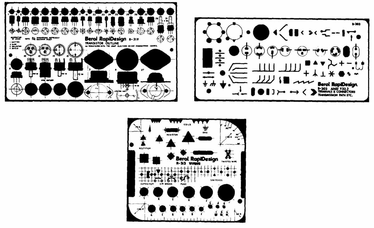
FIG. 23 Typical templates used in preparation of wiring diagrams. (Courtesy
of Berol RapiDesign)
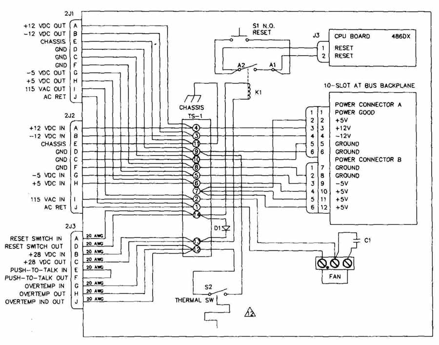
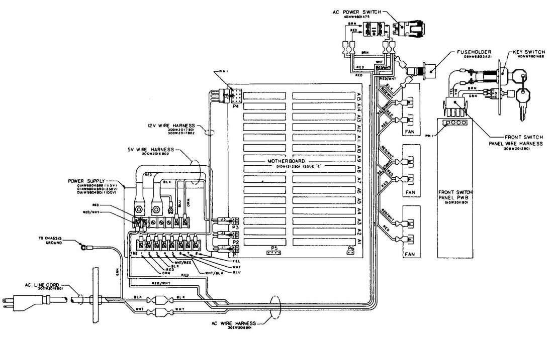
FIG. 24 Data-acquisition computer wiring diagram.
In general, all lineweights are the same on wiring diagrams and should be black, medium-weight lines. If necessary, you can use thin-weight lines for component outlines or symbols to avoid confusion and for the base line method, where the imaginary baseline is drawn with a black heavyweight line for emphasis.
Lettering is the same for wiring diagrams as for other diagrams. The wiring diagram requires extensive lettering. In addition to including some type of identification or reference designation for every component, each wire includes identification of all specifications. The lettering can be inclined or vertical and should be aligned to be read from no more than two sides. Frequently, to avoid confusion the wire- identification lettering is done with a break in the line representing the wire. The lettering is inserted in the break, as in FIG. 22, so that it is in line with the wire it is describing. This eliminates any doubt as to which line the identifying code accompanies.
Templates are strongly recommended for use in the preparation of wiring diagrams. FIG. 23 shows typical templates that are used to draw the component outlines in wiring diagrams.

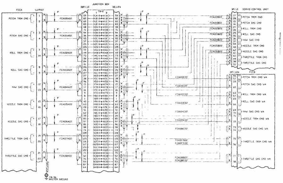
FIG. 25 Wiring diagram for junction box.
CAD WIRING DIAGRAMS
Remember that the use of CAD to prepare wiring diagrams and other drawings does not eliminate the need for a complete understanding of how these drawings are to be prepared. It is still the drafter’s responsibility to ensure accuracy and completeness in all drawings.
Figures 24 and 25 show examples of CAD-generated wiring diagrams.
REVIEW QUESTIONS
1 Why do wires come in many different sizes?
2 What is the primary purpose for the insulating material used on wires?
3 What characteristics should be considered when you choose wires?
4 What are AWG numbers and what are they used for?
5 What advantage does stranded wire have over solid wire?
6 Since stranded wires do not use the same type of AWG code as solid wires, how are stranded wires identified?
7 Why would a cable assembly be used?
8 When is a wiring harness most beneficial?
9 What are the major classifications of wiring drawings?
10 What kind of information is desired on wiring diagrams?
11 When is it most practical on a drawing to include every wire that is to be connected?
12 Which type of wiring diagram gives the least information of true physical relationship?
13 Why is it unnecessary to draw most wiring diagrams to scale?
14 Why should grid paper be used in the preparation of the wiring diagram?
15 When a harness assembly drawing is prepared, why is it often drawn full size?
PROBLEMS
1. Draw the geometric shapes of various component case styles shown in the following figure.

PROBLEM 1 Component shapes. (Courtesy of Texas Instruments, Inc.)
2. The telephone cable diagram in this figure demonstrates two types of terminations being used. Redraw this circuit on a B size sheet. Practice lettering by including the assembly instructions that are listed.
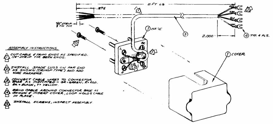
PROBLEM 2 Telephone cable diagram.
3. The following figure is a wiring diagram for a telephone recording attachment. Redraw this diagram on a B size sheet.

PROBLEM 3 Telephone recording attachment. (Courtesy of International Business
Machines Corporation)
4. A piggyback connector is used for a foot control microphone. Draw the piggyback connector shown in this figure on a C size sheet. Complete all the lettering on this drawing with the use of some lettering tool such as a Leroy letter set.
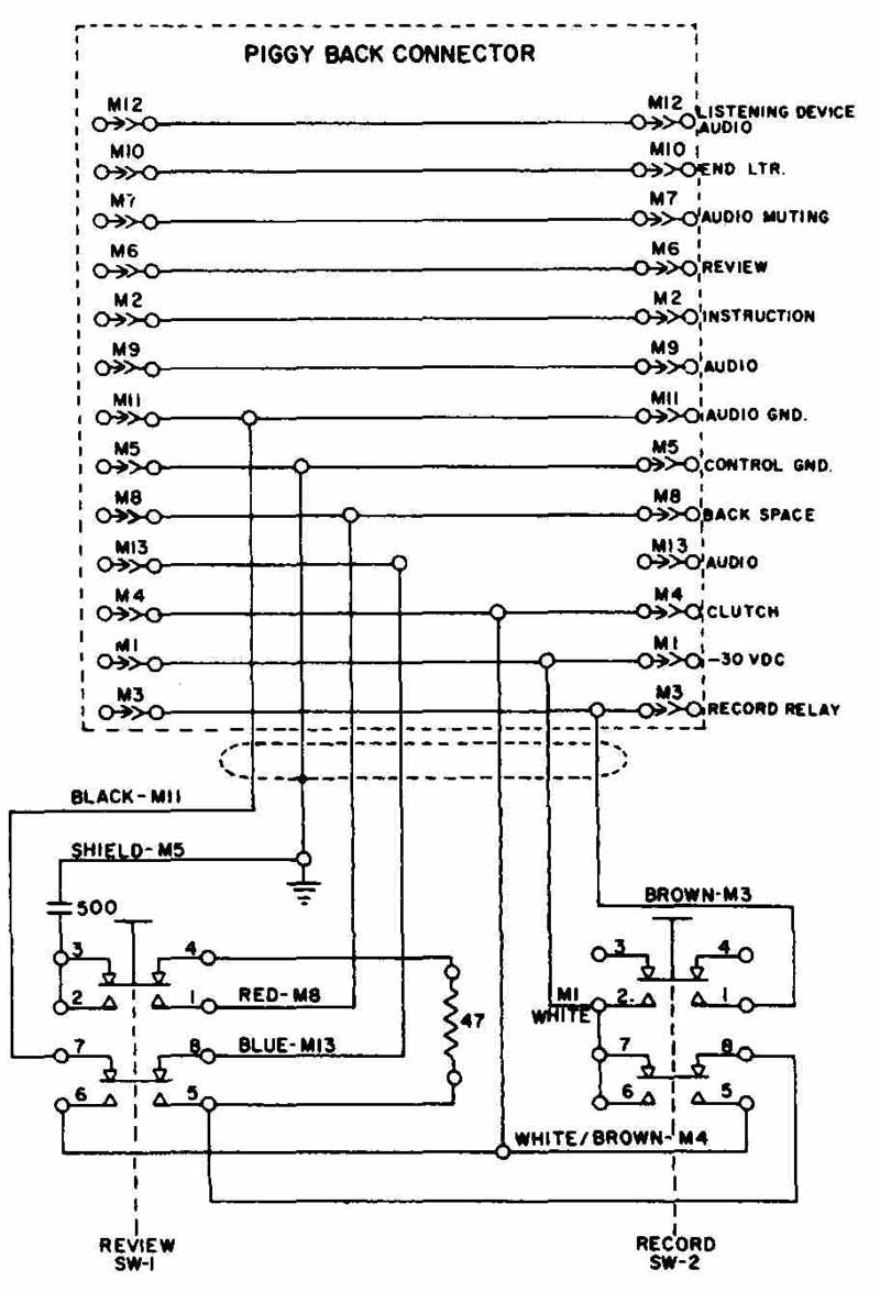
PROBLEM 4 Piggyback connector. (Courtesy of International Business Machines
Corporation)
5. Redraw FIG. 10 illustrating the use of numbering codes.
6. FIG. 14 demonstrates how the baseline extends just past the short feeder lines. Redraw this diagram on an A size sheet. Use ink and a lettering template.
7. Produce a table similar to the one in FIG. 16 for the baseline diagram shown in FIG. 14.
8. Redraw the wire harness assembly shown in FIG. 21. Include the additional views to fully describe the terminals.
9. (Advanced problem) A wiring diagram for a direct connection to a computer is shown in the following figure. Draw this on a C size sheet or larger.
PROBLEM 9 Chassis wiring diagram. (Courtesy of Motorola, Inc., Semiconductor
Products Sector)
10. Draw the wiring diagram on a D size sheet.
PROBLEM 10 Wiring diagram.

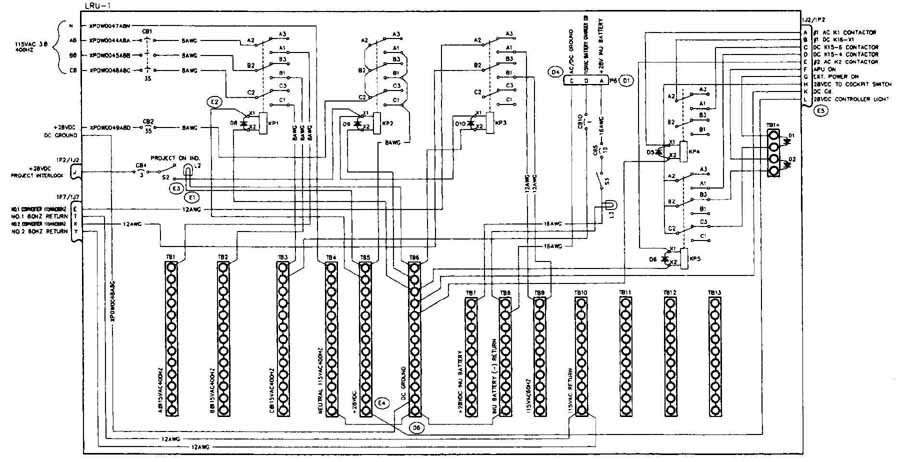
PROBLEM 11 Power distribution box wiring diagram.
12 Draw the air data system on a C size sheet.

PROBLEM 12 Air data system wiring diagram.
13. Draw the diagram of the data-acquisition computer shown in FIG. 24.
14. Draw the wiring diagram for the junction box shown in FIG. 25.
PROBLEM 15 Power and control wiring diagram.