By SKIP CAMPISI
Measure the voltage values of waveforms accurately and easily on your oscilloscope with the Voltage Cursor Adapter.
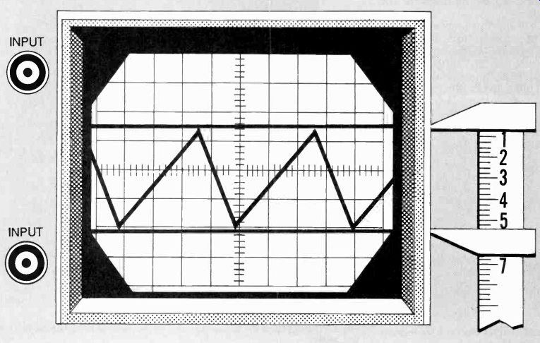
-------- THE CURSOR ADAPTER superimposes horizontal cursor lines on the
top and bottom of a waveform.
HAVE YOU EVER HAD TROUBLE measuring the voltage value of a waveform on an oscilloscope screen? Are you tired of counting graticule squares and "guesstimating" those values? If so, you need the Voltage Cursor Adapter, It superimposes horizontal cursor lines on the top and bottom of the wave form-a kind of electronic calipers-to permit direct readout of the voltage value. The cursor lines extend across the entire screen.
The lower cursor (think of it as the floor) is the zero-volt cursor and the upper cursor (think of it as the ceiling) is the precision DC reference voltage. The cursors can be placed on any parts of the waveform that you want to measure, and the voltage can be read directly from a turns counter coupled to a precision potentiometer.
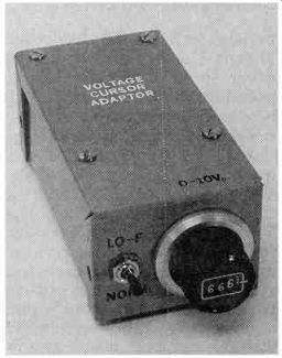
Figure 1 is the schematic diagram for the voltage cursor adaptor. The required 15 to 25-volt power to the circuit can be supplied either by batteries or a wall-mounted AC to 15-volt DC adapter. The author's prototype has a jack that will accept a plug from either the adapter or a battery pack consisting of two 9-volt batteries taped together.
The MC78L12 voltage regulator (IC1) supplies regulated 12-volts DC to the rest of the circuit. The ICM7555 timer (IC2), a CMOS version of the industry-standard 555, drives the CD4066B, a CMOS bilateral switch (IC3). This drive frequency can either be a normal frequency (NORM) of 100 Hz or a low-frequency (Lo-F) of 10 kHz, depending on the setting of switch S1. Set S1 to LO-F for in puts below 500 Hz.
The DC reference voltage supplied to pin 3 of IC3 is set by R3, a 10-turn, 5000-ohm precision potentiometer. The voltage can be read directly from a turns counter dial coupled directly to the potentiometer's wiper. The accuracy of this reading can be 1% or better. Trimmer potentiometer R1 permits the voltage to R3 to be calibrated to precisely 10 volts.
The circuit is calibrated by setting the digital reading on the turns counter of R3 to the full clockwise position and adjusting R1 for a reading of 10 volts at the wiper of R3 with a digital voltmeter.
Bilateral switch IC3 converts the DC reference to a square-wave with exactly the same wiper amplitude. The square-wave output appears on the common pins 4,9, and 10 of IC3 and coaxial plug PLI.
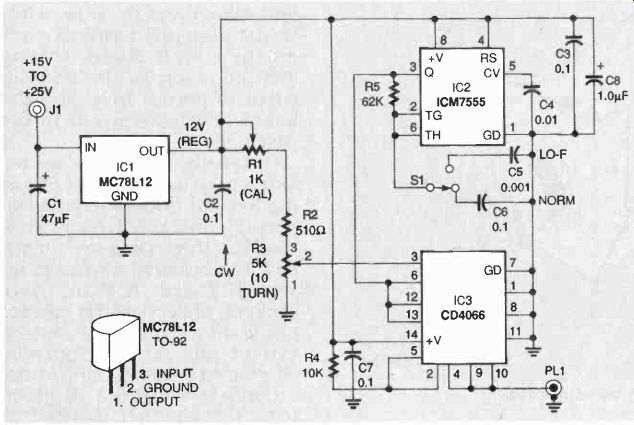
FIG. 1-SCHEMATIC DIAGRAM for the voltage cursor adapter. Power can be supplied
by batteries or an AC adapter.
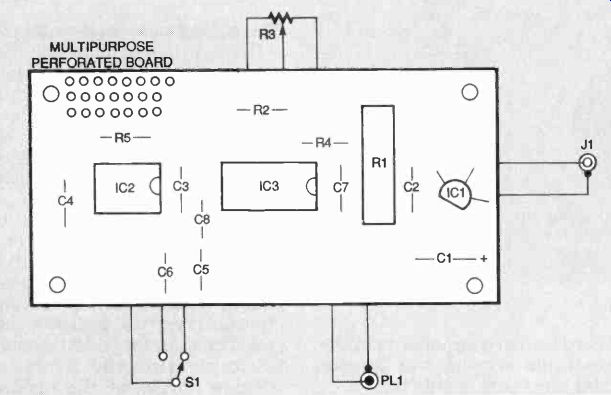
FIG. 2-USE THIS AS A GUIDE for positioning the parts on the perforated construction
board.
--------
PARTS LIST
Resistors: all fixed are 1/4-watt, 5%
R1--1000-ohm multiturn trimmer potentiometer, Bourns 3005P 101 or equiv.
R2-510 ohms
R3--5000-ohm, 7/8 in. precision potentiometer, ten-turn with matching multiturn dial, Clarostat 73JB with a 15-turn dial or equiv. (See text)
R4--10,000 ohms
R5--62,000 ohms
Capacitors:
C1--47µF, aluminum electrolytic, 35 VDC
C2, C3, C6, C7--0.1µF, ceramic
C6--0.1µF, polyester
C4--0.01µF, ceramic
C5-0.001µF, polyester
C8--1.0 uF, solid tantalum dipped
Semiconductors:
IC1-MC78L12 12-volt voltage regulator, Motorola or equiv.
IC2-ICM7555 CMOS timer, Harris or equiv.
IC3-CD4066B CMOS quad bilateral switch, Harris or equiv.
Other components:
S1-SPDT switch, miniature, panel-mounted. 3A
J1-coaxial jack, panel-mounted (to mate with power plug)
PL1-panel-mounted phone plug 1/2-inch dia.
Miscellaneous: multipurpose perforated board 12 1/2 2 x 22 7/32 (Radio Shack 276-150 or equiv.); project case, aluminum, 4 x 2 1/2. 1 5/8 in. (Radio Shack 270-239 or equiv.); one 8 pin DIP socket and one 14-pin DIP socket; four standoffs with screws, 13/46 inch; two 9-volt batteries with two snap connectors and attached plug or wall-mounted line AC to 15-VDC adapter, 50 mA; insulated hookup wire; solder; screws.
--------
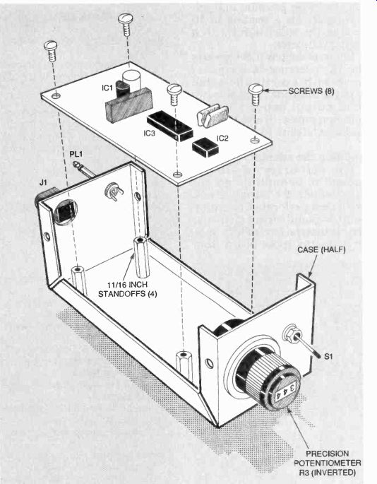
FIG. 3-HERE'S howeverYTHING MOUNTS inside the case.
------- EVERYTHING FITS EASILY inside the case.
Building the adapter
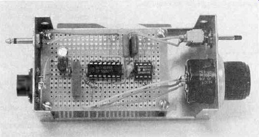
The circuitry is simple enough to be built on an approximately 2 x 3-inch stock predrilled perforated board by point-to-point wiring methods.
(The prototype circuit was built on a multipurpose board from Radio Shack.) There is nothing critical about component selection or placement. Figure 2 is a guide for positioning components on the circuit board.
The prototype was mounted in a two-part aluminum case that measured approximately 4 by 2 by 1 5/8 inches. If you intend to put the circuit in similar project case, use the blank circuit board as a pattern and mark the hole locations on that part of the case with the ends folded up.
It is recommended that both IC2 and IC3 be inserted in sockets. Insert and solder an 8-pin socket for IC2 and a 14-pin socket for IC3, as shown in Fig. 2. Insert and solder all other on-board leaded components in the positions shown, but do not trim any leads at this time.
Set the circuit board aside.
Refer to Fig. 3, the mechanical assembly diagram, and drill the holes that you marked on the case half for mounting the 3/4-inch standoffs. Then drill the holes for mounting jacks J1 and J2, precision potentiometer R3 with counter and switch SI in the case end surfaces.
Mount the jacks, potentiometer and switch on the case half.
Cut 3- to 4-inch lengths of No. 22 AWG stranded, insulated, hookup wires for making all connections to the board-mounted components, as shown in Fig. 2.
Note: A lower cost counter can be substituted for the digital readout dial used in the author's prototype.
Solder one end of the wires from the jacks, potentiometer and switch and the other ends to the assigned terminal pads on the circuit board, leaving enough slack in the hookup wires to permit inverting the board and fastening it to the case half.
Carefully check all solder joints to be sure they are free of inadvertent bridges or cold soldering. Check IC1 to be sure that the three pins are identified and soldered correctly. Insert IC2 and IC3 in their sockets, observing the correct pin locations. After the Voltage Cursor Adapter is completely assembled it is ready for testing.
Connect the times 10 probe from the channel B input of your oscilloscope to the output plug (PL1) of the Voltage Cursor Adapter.
Measuring waveform voltage
Display the signal whose voltage you want to measure by plugging a lead from the signal source into the channel A vertical amplifier jack of your oscilloscope. Set the triggering on channel A. The output is variable from 0 to 10 volts.
Set your oscilloscope's attenuators to accommodate the 0 to 10-volt range. Using the CHOPPED/ALTERNATE mode, position in the zero cursor with the channel B vertical position control. Then adjust potentiometer R3 to position the reference voltage cursor at the correct level on the signal waveform you want to measure.