By DOYLE WHISENANT
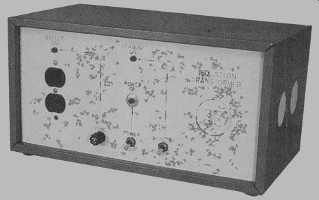
Bulls this inexpensive transformer to protect yourself--and your test equipment while you service and repair electronic appliances.
EVERYONE WHO REGULARLY services television sets really should have an isolation trans former. One side of the chassis of most line-powered TV receivers and tube-type radios is connected directly to the AC line. Therefore, servicing this electronic equipment can be very dangerous because the chassis can be "hot." An isolation transformer isolates the chassis of the equipment being serviced from the AC line. This article explains how to build an isolation transformer for a fraction of the price of a commercial product. It will even supply more current than most commercial units.
The heart of this project is the transformer. The author obtained the two transformers required from two discarded microwave ovens. Buying a new transformer for this project will not save you much money over buying a commercial isolation transformer because the trans former required can cost more than $150. For example, B&K Precision sells an isolation transformer for $189.00. Al though electronics distributor Mouser Electronics sells one for $63.50, it will supply only 2.17 amperes, or about 250 watts.
Even this modest price is al most three times what our complete project will cost!

Operation
Figure 1 is the schematic for the isolation transformer. Fuse-protected AC line power is first applied to power switch S1.
When S1 is closed, neon power indicator NE1 lights up, and power is applied to a cooling fan and to standby switch S2. This arrangement allows trans former power to be turned off, while permitting the fan to continue cooling the transformer.
Neon standby indicator NE2 is wired across switch S2 so that it lights when S2 is open.
When S2 is closed, power is applied to the primary side of 1:1 isolation transformer T1. The secondary side of T1 supplies isolated AC power to receptacle S01. Neon indicator NE3 lights when power is applied to the receptacle SO1.
The isolation transformer will supply 1000 watts for short periods of time, and 500 watts or less continuously. However, it will run too hot if 500 watts is exceeded for more than about half an hour.
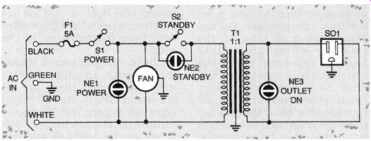
FIG. 1--ISOLATION TRANSFORMER SCHEMATIC. Switch S2 allows power to the
transformer to be turned off while the fan continues to cool the transformer.
The transformer for this project was made from the windings of two microwave-oven transformers. Microwave ovens have heavy-duty transformers (see Fig. 2) that consist of three windings: a 120-volt AC input coil, a 2000- to 3000-volt AC output coil, and a 3- to 5-volt AC coil that serves as the filament winding for the oven's magnetron. The magnetron is the vacuum tube that produces the microwave energy for the oven.
The filament winding is easily identified; it consists of three to five single turns of 12- or 13-gauge enamel-covered wire.
This winding is usually wound directly over the 120-volt AC winding which is wound from approximately the same size wire as the filament, but it has more turns. The high-voltage winding, which will be discarded for this project, consists of many turns of much smaller gauge wire.
The microwave oven's fan or blower that cools the magnetron is also needed for this project. The transformer will run warm under load, and the oven fan is an economical way to keep it cool. None of the other parts (see the Parts List), while commonly available, will be found in a microwave oven.
Modifying the transformer
Locate two surplus or discarded microwave ovens that are identical, or as similar as possible. As stated earlier, the transformers from two ovens are needed to build the isolation transformer. These transformers usually remain in good working condition. As an alter native, two surplus transformers might be easier for you to obtain than two scrap micro wave ovens.
The pencil in Fig. 2 points to one of the welds that must be removed from the microwave-oven transformer. With a hand held grinder, very carefully grind away the welds on both sides of the transformer and separate the top core from the base. Figure 3 shows a trans former that has been disassembled. Remove the windings from the core, being careful not to disturb the insulation on the windings. Discard the high-voltage windings.
The 120-volt AC input coils from the two transformers will be used to make the isolation transformer. Place both 120-volt coils back on the core of one of the transformers to form a 1:1 isolation transformer. Do not disturb the insulation on the windings when reinstalling them on the core. Place the windings very close to one an other to ensure satisfactory transformer coupling. Some transformers have spacers be tween the coils and the core (see Fig. 4) that must be replaced in the correct locations.
Once the windings are correctly positioned back on the core, reinstall the base of the transformer. To do this, weld the base back onto the trans former. If you have access to an electric welder and know how to use it, do this yourself. Other wise, take the transformer to a welding shop and let a skilled welder do the job for you. Regardless of who does the welding, make sure that the trans former core does not get too hot and that sparks from the welder don't burn the insulation on the coils.
Check the completed transformer with an ohmmeter to make sure that there are no short circuits to the core and from coil to coil. Test the trans former by connecting a volt meter to the leads of one coil designated as the output coil.
Connect the leads from the other coil to an AC line cord through a 5-ampere fuse. Insulate all exposed connections.
Power up the transformer just long enough to get a reading on the voltmeter. Record the output reading, disconnect the AC power, and reverse the input and output coil connections.
Repeat the procedure and check the output voltage again. Deter mine which output coil voltage measures closest to 120-volts AC; it will be the output side.
The prototype transformer had a lower voltage reading in one direction than in the other.
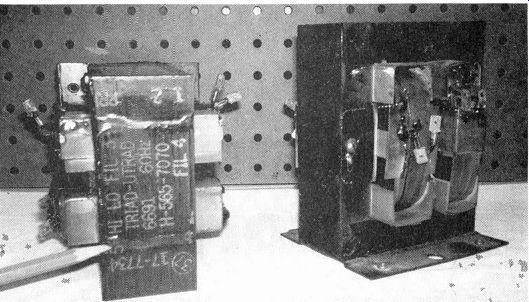
FIG. 2--THE TRANSFORMER for this project was made from two discarded micro
wave-oven transformers.
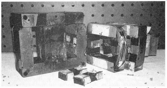
FIG. 3--DISASSEMBLED TRANSFORMER. Remove the windings from the transformer
core. being careful not to disturb the insulation on the windings. Discard
the high-voltage windings.
Construction
This project requires a sturdy metal case that measures approximately 14- x 7- x 9-inches to hold both the fan and the transformer, and still have room for all connections.
This project consists of only a few parts, so point-to-point wiring can be used throughout.
Figure 5 shows the inside of the prototype unit. Test fit the fan and the transformer before drilling any holes in the case. The fan should be mounted so that its air stream is directed at the transformer. Once the correct positions are determined for the fan and transformer, mark the locations and drill the mounting holes, but don't mount any thing yet.
If you purchase the case specified in the Parts List, you will find that many of the necessary holes are already punched out.
Otherwise, prepare the en closure by drilling a hole and mounting the line cord to the back of the enclosure. Prepare the front of the enclosure by drilling holes to mount the neon indicators, NE1, NE2, and NE3.
Then drill holes for switches S1 and S2. The prototype unit has two large holes punched in each end to allow the fan to draw in cool air and exhaust hot air.
Place a screen over those holes to prevent debris from being drawn inside the unit. Prepare an opening for the duplex receptacle on the front panel with a nibbling tool.
Once all the metal working on the enclosure is complete, It can be painted. Next label the en closure; the labels can be protected with clear spray enamel.
When the enclosure is completely dry, the transformer and fan can be mounted. Start with the transformer, mounting it to the base of the enclosure with rubber washers to reduce vibration. Mount the fan in the direction so that the cooling air flow will be blowing over the trans former. Next install the fuse holder, the line cord, the three neon indicators, switches S1 and S2. and the duplex receptacle S01.
=======
PARTS LIST
T1-Modified microwave oven transformer (see text)
F1-5-ampere fuse and panel-mount fuse holder
S1, S2--SPST 15-ampere toggle switch
NE1-NE3--120-volt AC neon indicator lamp
S01-Standard duplex AC receptacle
Metal case (Mendleson Electronics, 1-800-344-4465, Part No. 160-1782F or other suitable en closure), grounded AC line cord, cooling fan from old microwave oven (see text), 14- to 16-gauge wire, terminal blocks, solderless connectors, wire ties, hardware
=======
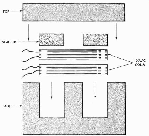
FIG. 4--SOME TRANSFORMERS have spacers between their coils and the core.
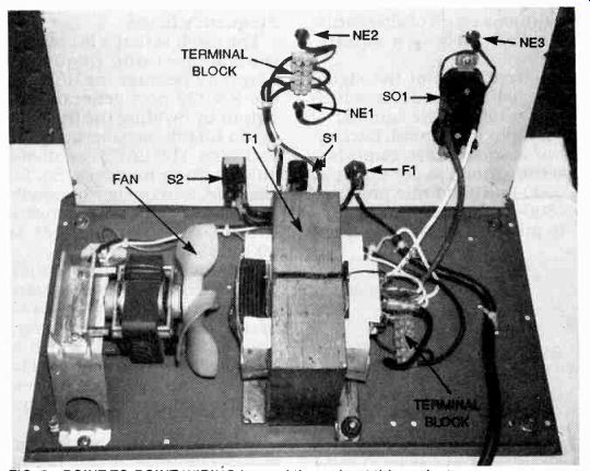
FIG. 5--POINT-TO-POINT WIRING is used throughout this project.
The isolation transformer can produce several amperes of cur rent, so use 14- to 16-gauge wire for all connections to and from the transformer. However, smaller gauge wire can be used for connecting the fan and neon indicators.
Refer to the schematic diagram (Fig. 1) and begin the wiring by connecting the hot side of the line cord (black wire) to one side of the fuse holder. Next solder a wire from the other side of the fuse holder to one terminal of the main power switch, S1.
Connect the other terminal of Si to the other side of the fan and to one terminal of S2. Connect power indicator NE1 across the fan terminals so it will indicate when power is applied to the fan and to S2.
Standby switch S2 allows power to the transformer to be shut off while still allowing the fan to work. Wire indicator NE2 across S2 so that it illuminates when S2 is open, or when the unit is in the standby mode.
Next, connect S2 to the other side of the transformer. Connect the neutral (white) wire from the line cord to one side of the fan and also connect it to one terminal on the input side of the transformer.
Connect both output leads of the transformer to the AC receptacle S01. Next connect the output-power indicator NE3 across the receptacle. As a last important step, run a ground connection from the line cord (the green wire) to the base of the transformer and to the fan. If the transformer has not been grounded to the chassis, be sure to do so now with a separate wire.
Before closing up the case, plug an appliance such as a coffee maker, a lamp, or another appliance that draws about 500 watts into the isolation trans former outlet and turn on the power. Run the transformer with the load turned on for approximately 30 minutes while checking it every five minutes or so for excess heat.
The prototype was tested with an 800-watt coffee maker, and the transformer ran warm--but not hot--to the touch. Do not use the isolation transformer to power anything with that high a power rating for extended periods of time.
adapted from: Electronics Now--Electronics Experimenter's Handbook 1996