by CARL J. BERGQUIST
Build this full-featured breadboard laboratory, and add custom features to suit your own needs.
One of the most gratifying benefits of being an electronics hobbyist is the opportunity to design and build custom projects for a particular need or purpose. The incredible number of new integrated circuits that are introduced each year provides building blocks for circuits and fertile ground for experimentation in electronics.
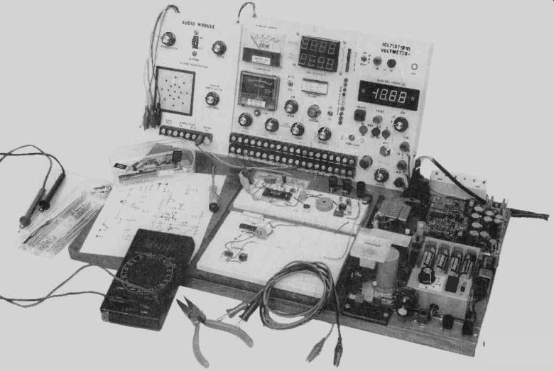
One requirement for successful prototyping and experimentation is a quick, convenient way to connect and disconnect components. Solderless breadboards are a good start, but all too often one is likely to end up with the board in the center surrounded by a maze of wires that connect switches, potentiometers, meters, power supplies, and any number of other components that dangle in all directions. The arrangement of components can be both frustrating and irritating. The solution is to combine the bread board, power supply, and other commonly used parts into a self-contained unit.
Factory-made laboratories like that are available, but they can be quite expensive. The lab described in this article, how ever, combines economy. expansion, and easy customization you can use many of the parts you might already have on hand in your junkbox.
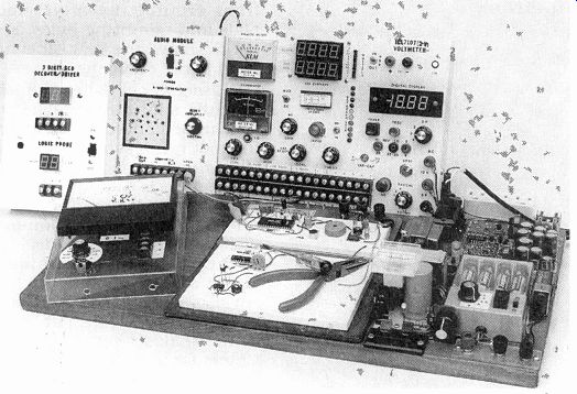
FIG. 1--BASIC PROTOTYPING LAYOUT. The base can be raised to make room for
plastic drawers, power transformers, or other equipment.
Design
The prototyping station base consists of a 20-inch length of 1-by 12-inch pine board that is sanded, stained and finished.
The various power supplies are located to the right; the center section is reserved for three breadboards and the main equipment backboard. The left side is left open to accommodate additional modular back boards, or any other peripherals such as keypads or data-entry terminals. The base can be raised to make room for plastic drawers, power transformers, or other equipment. Rubber feet can be used to ensure that the lab is stable on the bench. That basic layout is shown in Fig. 1.
Power supplies
Since the availability of power is always a requirement for successful prototyping, a variety of different power sources is incorporated on the right-hand section of the station (Fig. 2 shows a close-up view of the power section). The first power supply on the upper left is a surplus Texas Instruments computer board, bought at a clearance sale for $5. With the addition of an LED indicator, it provides a good clean source of ± 5 volts and +12 volts. Being a computer-grade supply, the outputs are well-regulated, well-filtered, and can output about 1 ampere each. Power for this supply comes from an off-board wall-outlet transformer, and it is in put to the supply via a two-position pushbutton terminal (the kind you might see on the back of a speaker).
Since a standard dry cell is appropriate to power many circuits, the second supply shown on the upper right of Fig. 2 consists of four AA cells and one 9-volt battery. The case from an old nickel-cadmium battery charger holds the AA cells, and a rotary switch and power indicator were added. The battery holder is tapped at each of the four positive battery pads, and each pad is wired to one pole of the rotary switch. The 9-volt battery is wired to a fifth pole on the rotary switch. This allows the selection of 1.5, 3, 4.5, or 6 volts DC from the AA pack, and 9 volts from the 9-volt battery.
The LED indicator is a 0.3-inch high, seven-segment display, with all segments turned on to form an "8," which is a more noticeable reminder of the "on" status of the battery pack than a single LED. The output from this supply is connected to two of three binding posts for easy access. The third binding post is the negative 5-volt supply from the TI computer supply.
Another voltage source is provided by a +1.2- to 20-volt DC variable power supply that was built from a kit some years ago.
The potentiometer next to the battery pack allows for adjustment of the output voltage, which is available at another two-position pushbutton terminal. An analog meter indicates the voltage at the pushbutton terminals.
Next to the variable supply is a 12.6-volt, center-tapped trans former, complete with a switch and indicator LED, that provides 6- and 12-volts AC. An SPST slide switch is connected to one side of the 120-volt AC input to the transformer primary. The outputs are wired to multipurpose posts on the main backboard.
AC power is made available at a triple-outlet AC strip, which gets its power via a heavy-duty line cord. The power inputs for the AC and variable supplies are also connected to this line cord.
The five separate power sup plies can be customized to suit your needs. If you decide to en close the power supplies, be sure to provide for adequate ventilation to allow heat to escape. The main 120-volt AC in put should be protected against surges and spikes if you anticipate prototyping computer circuits.
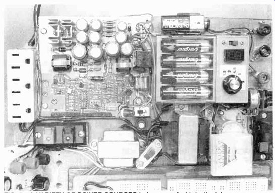
FIG. 2--A VARIETY OF POWER SOURCES is incorporated into the lab.
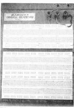
FIG. 3--THREE 640-POINT breadboards are laid out side-by-side. The top bread
board is on a metal base with three multipurpose posts, and the other two are
plug-in panels mounted on a plywood base.
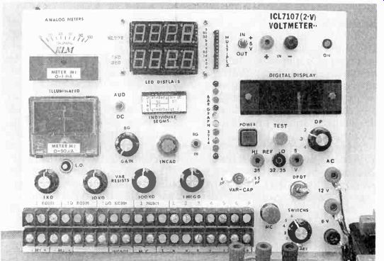
FIG. 4--THE MAIN BACKBOARD occupies about 10 Inches across the back edge of
the base. The backboard holds many of the accessories.
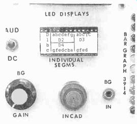
FIG. 5--A BARGRAPH is mounted in the center of the backboard.
Breadboards
In the center of the base board are three 640-point solderless breadboards, laid out side-by-side (see Fig. 3). The top bread board is a Radio Shack unit on a metal base with three multipurpose post's. The other two breadboards are plug-in panels mounted on a plywood base. All three breadboards have dual two-connection bus lines at their tops and bottoms, and will accommodate SIPs, DIPs, discrete components, and jumper wires. While this breadboard arrangement has provided the author with enough space and has been versatile enough for all of his projects to date, it is certainly not the only arrangement possible. The breadboards are available in a variety of shapes and sizes, with from 250 con tact points to 2500 or more.
Some thought about the types of circuits you’ll be working on will help you make a final decision on this part of the lab.
Backboards and modules
The main function of the backboard is to support more cumbersome components, modules, and any other circuits that the builder wants to add items such as switches, potentiometers, meters, displays. The main backboard occupies about 10 inches across the back edge of the base (see Fig. 4).
Two 19-position terminal strips provide access to the parts mounted on the back board. The strips on the prototype were removed from a surplus alarm board. The screw terminals allow connections to be made with alligator clips, bare wire, and spade lugs. How ever, spring-loaded terminals, SIP sockets, or any other connector you might have on hand can be used here. Each point on the terminal strips is wired to a connection on the component, and labeled for identification.
The row of components above the terminal strips consists of four potentiometers (1-, 10-, and 100-kilohms and 1 megohm) and a 4- to 55-pF vari able capacitor. lb the right of that row is a DPDT toggle switch, momentary control (MC) switch, and six-position rotary switch. The binding posts on the extreme right out put the 6- and 12-volts AC, previously mentioned.
========
PARTS LIST--MAIN UNIT
Resistors:
1K panel-mount potentiometer 10K panel-mount potentiometer 100K panel-mount potentiometer 1 megohm panel-mount potentiometer
Capacitors:
4 to 55 pF variable capacitor
Semiconductors:
One 0.3-inch 7-segment display, common anode
Four 0.56-inch 7-segment displays, common anode (MAN6710) or four 0.56-inch 7-segment displays, common cathode (MAN6740)
Power supplies:
Texas Instrument surplus computer power supply, or equivalent 12.6-volt AC transformer
4-AA battery holder
9-volt battery connector
1.2 to 20 volt variable DC supply
120 VAC power strip
Other components:
Two spring-loaded speaker-type terminals, six binding posts, 6-foot AC line-cord, plastic project cases, three 640-point breadboards, two 19-point terminal strips, heavy-duty DPDT toggle switch, momentary pushbutton switch, 6-position rotary switch, 0 to 1 mA analog meter movement, small push-on push-off switch, 11-pin SIP socket, 28-pin DIP socket, bayonet lamp socket with lens and bulb assortment, hookup wire and zip cord, hardware, seven pan el knobs, TO-220 10-watt heatsink, 4-contact tie point.
PARTS LIST--BARGRAPH
IC1-LM3914 bargraph driver and 18-pin DIP socket. National Semiconductor R1-1000 ohms, 1/4-watt resistor R2-5000 ohms, panel-mount potentiometer with switch
T1--audio transformer, 1K primary, 8-ohm secondary (Radio Shack 273-1380)
J1--1/2-inch phono jack and plug
D1-1N4001 diode
LED1-LED10-light-emitting diode, any color
S1--DPDT switch
=========
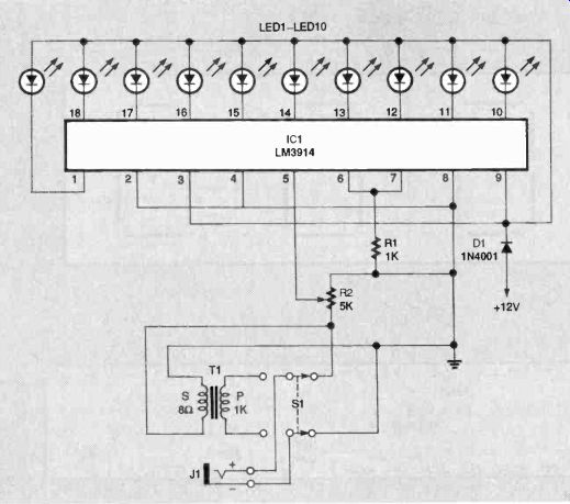
FIG. 6--LED BARGRAPH SCHEMATIC. The circuit consists mainly of an LM3914 bargraph
display driver IC. X
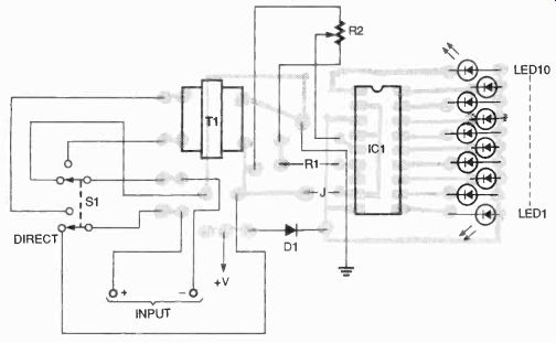
FIG. 7--PARTS-PLACEMENT DIAGRAM for the bargraph circuit.
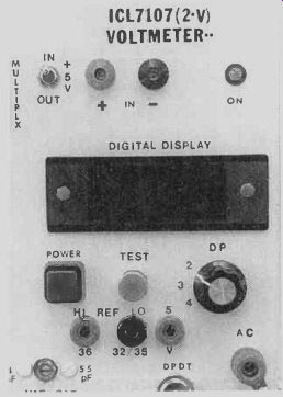
FIG. 8--A 3 1/2-DIGIT VOLTMETER occupies the upper right hand corner of the
backboard.
On the left side are two analog meters (M1 and M2). Meter M1 is rated for 0 to 1 milliampere, which is a useful value for many circuit designs, and M2 is 500 microampere, ± center scale unit. This is essential when de signing a circuit where the out put can swing either positive or negative. Meter M2 is illuminated, and the small push-but ton switch labeled L.O. activates the 6-volt lamp.
A bank of seven-segment LED displays is mounted in the top center of the backboard. The first row of four is in a multiplexed arrangement, with all like segments tied together.
Connection to the multiplexed displays is accomplished via the SIP socket to the right, which is labeled accordingly. The second row of seven-segment displays is wired as a 3 1/2-digit display that allows individual access to each of the 24 segments and the common anode. Connections to this display row are made via the DIP socket below it, which is marked appropriately for use with digital circuits having that type of output.
Below the DIP socket is an in candescent lamp indicator with a bayonet-type socket. Bulbs are easily changed, and they are available in 6-, 12-, 14-, and 28-volt versions.
========
PARTS LIST--VOLTMETER
IC1-ICL7107CPL A/D converter/LED display driver, Harris
DISP1-two 2-digit common-anode 7-segment displays (MAN6710 or equiv.)
C1--0.22 uF, mica capacitor
C2--0.047 uF, mica capacitor
C3--0.01 uF, mica capacitor
C4--0.1 uF, mica capacitor
C1--100 pF ceramic disc capacitor
R1--470,000 ohms, 1/4-watt, 5% resistor
R2--1 megohm, 1/4-watt, 5% resistor
R3-25,000 ohms, PC-mount potentiometer
R4-22,000 ohms, 1/4-watt, 5% resistor
R5-100,000 ohms. 1/4-watt, 5% resistor
S1-SPDT toggle switch
Miscellaneous: pushbutton switch, 3-position rotary switch, five banana jacks. green LED
PARTS LIST--BCD DECODER
IC1-74LS48 BCD to 7-segment decoder
IC2-CD4553 3-digit BCD counter, Harris
Q1-Q3-2N3906 PNP transistors
R1-R7-220 ohms, 1/4-watt, 5% resistor
R8-R10-1000 ohms. 1/4-watt, 5% resistor
C1-0.001 µF, ceramic disc capacitor
DISP1-three common-cathode 7-segment displays
=========
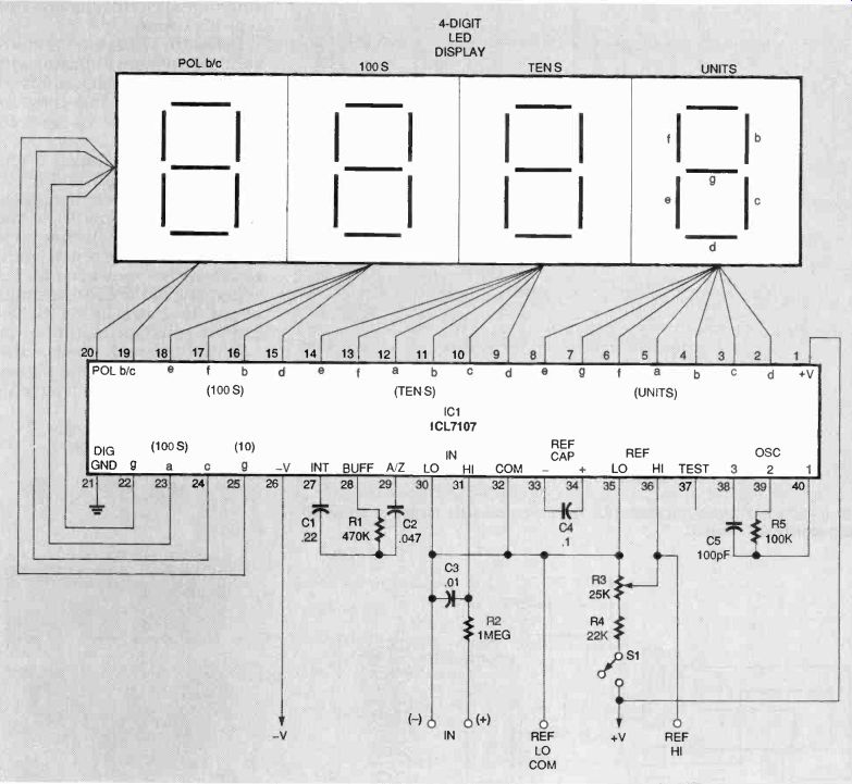
FIG. 9-THE SCHEMATIC DIAGRAM of the voltmeter circuit.
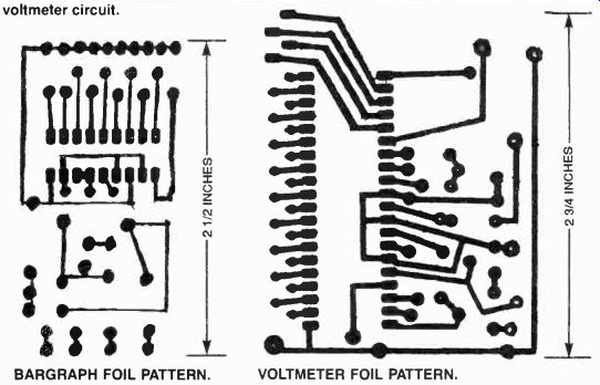
---------- BARGRAPH FOIL PATTERN --- VOLTMETER FOIL PATTERN.
The author installed a ten-step LED bargraph and a 3 1/2-digit voltmeter on the back board, both as a matter of personal preference. The bargraph is mounted in the center of the backboard as shown in Fig. 5. A schematic of the LED bargraph circuit is shown in Fig. 6. The circuit consists mainly of an LM3914 bargraph display driver IC. Switch S1 allows signals to be input to the driver chip directly, or through a matching transformer T1 for audio.
Signals are input to the bar-graph circuit at J1, a 1/2-inch mini phono jack. The 5-kilohm potentiometer (R2) controls gain. The author used a potentiometer with a built-in on/off switch so that power to the bar-graph display could be turned on and off independently. You can either do the same, or use a separate switch for power.
Power for the bargraph circuit is provided by the TI computer supply.
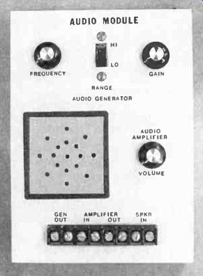
FIG. 11-THE AUDIO MODULE consists of an audio generator, an amplifier, a speaker,
and a terminal strip.
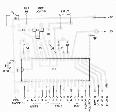
FIG. 10-PARTS-PLACEMENT DIAGRAM for the voltmeter circuit.
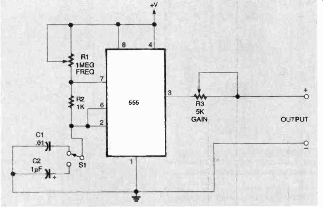
FIG. 12-SIGNAL GENERATOR. Potentiometer R1 sets the output frequency.
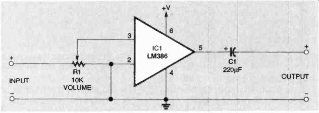
FIG. 13-AUDIO AMPLIFIER. This circuit has a gain of about 20.
=========
PARTS LIST--AUDIO AMPLIFIER
IC1-LM386 audio amplifier, National Semiconductor
R1--10,000 ohms, panel-mount potentiometer with switch (or use separate potentiometer and switch)
C1--20 uF, 25 volts, electrolytic 8-position terminal strip 1 1/2-inch, 8-ohm speaker
PARTS LIST--METER
M1--4- to 6-inch, 0 to 1 mA analog-meter movement
S1--8-position rotary switch
D1--1N4002 diode
R1--10 ohms, N-watt, 5% resistor
R2--100 ohms. 1/4-watt, 5% resistor
R3--1000 ohms, 1/4-watt, 5% resistor
R4--10,000 ohms, 1/4-watt, 5% resistor
R5--100.000 ohms, 1/4-watt, 5% resistor
R6--1 megohm, 1/4-watt, 5% resistor
R6--10 megohms, 1/4-watt, 5% resistor
Two banana jacks
====
PARTS LIST-AUDIO MODULE
ICI-LM555 timer R1-1 megohm, panel-mount potentiometer with switch R2-1000 ohms, 1/4-watt, 5% resistor R3-5000 ohms, panel-mount potentiometer C1-0.01 uF, Tantalum C2-1 F, Tantalum S1-SPDT switch
=====
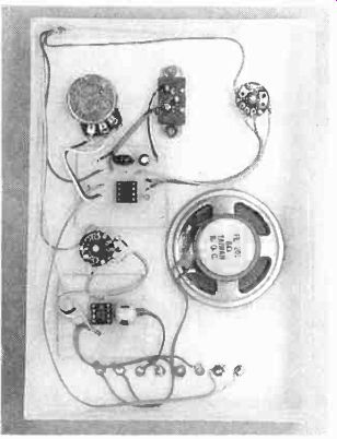
FIG. 14--THE AUDIO MODULE is too simple to call for a PC board, so point-to
point wiring was used.
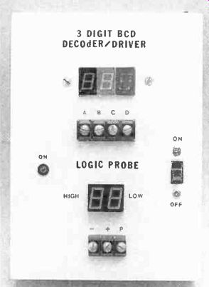
FIG. 15--3-DIGIT BCD DECODER-driver is another practical function block.
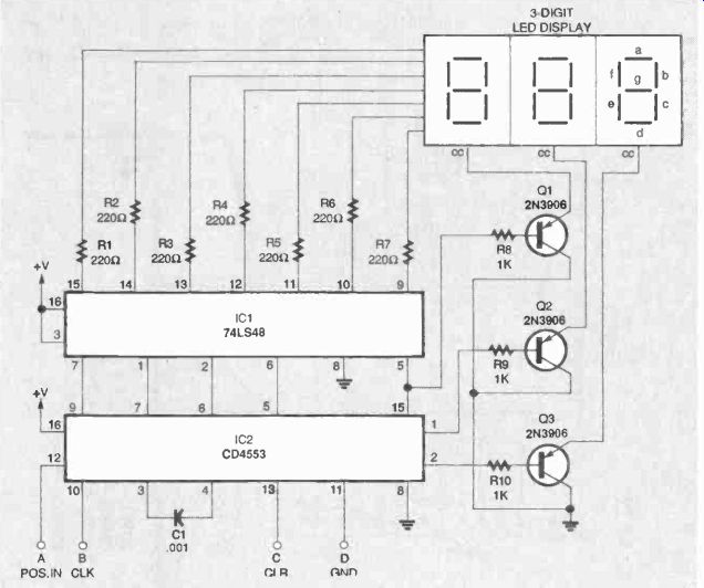
FIG. 16--THE BCD DECODER-DRIVER circuit will interface with any standard BCD
output to produce a digital display.
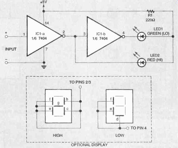
FIG. 17--A LOGIC PROBE is also included in BCD decoder module. The red LED
lights to indicate a logic high, and the green LED lights to indicate a logic
low.
PARTS LIST--LOGIC PROBE
IC1--7404 hex inverter
R1--220 ohms, 1/4-watt, 5% resistor
LED1--green light-emitting diode
LED2--red light-emitting diode
Two common-anode 7-segment displays (optional. see text) source
A foil pattern is provided for the bargraph circuit, and the parts-placement diagram for it is shown in Fig. 7.
The 3 1/2-digit voltmeter occupies the upper right hand corner of the backboard, as shown in Fig. 8. Figure 9 is the schematic diagram of the voltmeter circuit. A foil pattern is provided for this circuit, and Fig. 10 is its parts-placement diagram. This circuit can also be point-to-point wired. The circuit contains a Harris ICL 7107 analog-to-digital converter/ display driver. A standard 2-volt configuration was chosen for this circuit. Switch Si allows the + 5-volt source to be routed either to the on-board 25-kilo-ohm potentiometer, or to an external jack, depending on the need. To calibrate the meter, apply 1.2 volts from the variable power supply to the input, and adjust R3 until the display reads 1.200. Then, switch the input leads, and the display should read (-1.200).
The left side of the base is re served for add-on modules, which can have a number of different functions depending on what is needed. The audio module shown in Fig. 11 consists of an audio signal generator, an amplifier, a speaker, and a terminal strip. The signal generator circuit, shown in Fig. 12, consists of an astable 555 oscillator circuit, in which R1, in conjunction with C1 or C2, sets the output frequency. Switch Si selects either the 0.01-µF capacitor that generates frequencies from 20 hertz to about 5 kilo hertz, or the 1-µF capacitor that generates frequencies from 2 to 10 kilohertz. Potentiometer R3 controls gain or volume.
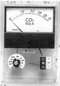
FIG. 18-THE METER MODULE contains a factory-made 0- to 1-milliampere movement.
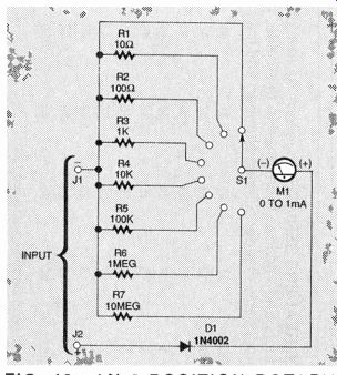
FIG. 19-AN 8-POSITION ROTARY SWITCH allows the input to be connected either
directly to the negative meter pole, or through one of seven dropping resistors.
The audio amplifier circuit (Fig. 13) uses an LM 386 in a basic configuration. With just three components, a gain of about 20 is achieved: that can amplify the signal from a micro phone, a Walkman-type radio, or any similar audio gear. The amplifier outputs about 500 milliwatts; if more power is needed, install an LM 380 amplifier IC that produces about 2 watts. Potentiometer R1 acts as a volume control by limiting the input voltage. The input and output to the amplifier are accessed from the terminal strip, as are the speaker and signal generator. This circuit is so simple that point-to-point wiring is used, as shown in Fig. 14.
The three-digit decoder-driver shown in Fig. 15 adds an other practical function block.
The circuit, shown in Fig. 16, will interface with any standard BCD output to produce a digital display. The circuit contains a CD4553 three-digit BCD counter and a 74LS48 seven-segment decoder. The decoded data is routed to a three-digit, common-cathode display.
A logic probe is also included in the BCD decoder module.
This simple circuit will indicate logic status, either high or low, at any given test point. Figure 17 is the schematic of the logic probe, which lights the red LED (LED2) for high logic levels, and the green LED (LED1) for low. If desired, common-anode, seven-segment displays can be substituted for the single LEDs.
The cathodes of the b, c, e, f, and g segments of one display can be wired together to form an "H" to indicate a high, and the f. e, and d segments of the second display can be wired together to form an "L" to indicate a low.
The meter module shown in Fig. 18 makes use of a factory-marked 4 1/2-inch. 0- to 1-milliampere movement. bought at surplus. As shown in Fig. 19. an 8-position rotary switch (S1) al lows the input to be connected either directly to the negative meter pole, or through one of seven dropping resistors ranging in value from 10 ohms to 10 megohms. When using this meter, it is best to start with the highest setting, and then work down to prevent pinning the pointer.
adapted from: Electronics Now--Electronics Experimenter's Handbook 1996