By MARC SPIWAK
Build an accurate, 3 1/2-digit, handheld thermometer from a kit or from scratch.
THE LIQUID-CRYSTAL DISPLAY (LCD) and the single-chip analog-to-digital converter (ADC) have made possible an almost endless list of battery-powered, hand held test instruments.
The most prominent of these are the digital multimeter (DMM) and the digital panel meter (DPM), but others include digital capacitance meters, thermometers, timers, sound-level meters, and light meters.
The single chip ADC eliminated a slew of discrete components and increased circuit re liability, while the LCD presents large characters that are easily seen in daylight. But of more importance in battery-powered instruments, both of these components are miserly in power consumption. This is especially important for battery conservation.
Within recent years the prices of single-chip ADC ICs and large-character LCDs have fallen, and they are now readily available as low-cost, off-the-shelf items from electronics stores and distributors.
The digital thermometer de scribed here can be made from an available kit or the parts can be obtained from most electronics distributors. By building the thermometer, the builder will gain experience in working with advanced ICs and display modules, and at the same time gain insight into circuitry common to many different instruments.
The digital thermometer can make accurate, reliable, and repeatable temperature measurements in the laboratory or in the field over a wide range of temperatures. It will save money over the price of a factory-built instrument and, as a bonus, it provides circuit board space for adding extra components for experiments.
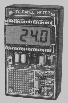
The basic digital thermometer circuit displays temperature in degrees Celsius to a an accuracy of a tenth of a degree on its 3 1/2-digit LCD in half-inch high characters. The PC board can be purchased as part of the kit or made with the foil pattern included here. The electronic components are visible on the top surface of the instrument case, as shown in the illustration of the meter.
How does it work? Figure 1 is a schematic for the digital thermometer. The key semiconductor device in the circuit is IC1, an ICL7106CPL single-chip analog-to-digital converter from Harris Semiconductor. It is a 3 1/2-digit ADC with a built-in LCD display driver, BCD to seven-segment decoders, clock and voltage reference. The ADC is packaged in a 40-pin plastic DIP In the digital thermometer described in this article, IC1 will be set to display 200 millivolts full scale (199.9), plus or minus.
The temperature sensor for this digital thermometer is an NPN transistor modified to act like a silicon diode.
The base of transistor Q1 is short-circuited to the collector, so it functions as a diode. How ever, it has a response curve that is more linear over a wider tempera ture range than a diode.
Transistor Q1 provides a variable input voltage to ICI. The voltage drop across the effective diode, typically about 0.7 volt, depends on the temperature of the diode's junction and the current flowing through it. The voltage drop is nearly linear, and will typically vary by 2.2 millivolts per degree Celsius.
A silicon diode has a negative temperature coefficient. Thus, in this application, as the temperature rises, voltage falls, and as the tempera ture falls the voltage rises. For example, if the ambient temperature rises by 2° Celsius, the voltage drop across the diode will decrease by about 4.4 milli volts. This linear voltage drop is measured to determine temperature.
The kit for the digital thermometer includes two transistors (Q1 and Q2) identified as BC-547s (but marked C547B).
Pin identification is shown in Fig. 1. However, more readily available, industry-standard 2N2222 transistors can be substituted, although they have different pinout arrangements.
Refer to the instructions given later if you want to make this substitution.
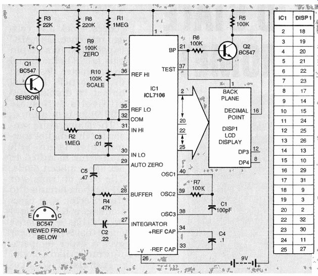
FIG. 1--SOLID-STATE THERMOMETER SCHEMATIC. The ICL7106 contains an analog-to-digital
converter, BCD to 7-segment decoders, display drivers, a clock, and a reference
voltage source.
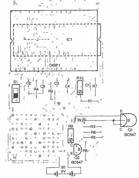
FIG. 2--PARTS-PLACEMENT DIAGRAM. IC1 is located beneath the liquid-crystal
display module.
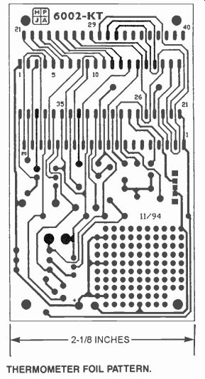
------- THERMOMETER FOIL PATTERN.
Trimmer potentiometers R9 (zero control) and RIO (SCALE control) can be set to zero the meter and make scale adjustments in the input voltage to IC1. A display of 00.0 must correspond to zero degrees Celsius and the display temperature must increment in degrees Celsius. The multiturn potentiometers permit precise settings.
Because IC1 can also indicate the polarity of the input voltage, the digital thermometer is theoretically capable of displaying temperature measurements from- 200 to + 200 degrees Celsius. However, the transistor used as a temperature sensor and its leads could be damaged by those temperature extremes.
The digital thermometer is effectively a solid-state volt meter that could be adapted for making other measurements such as voltage, current, power, light level, and sound intensity, and more. If the output of the sensor for the variable you want to measure can be scaled be tween 0 and 200 millivolts, the circuit presented here can display that variable in appropriate standard units with little or no circuit modification.
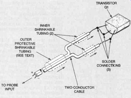
FIG. 3--THERMAL PROBE. The base and collector leads of transistor 01 are bent
together and soldered near the transistor's base and a two-conductor cable
is attached.
======
PARTS LIST
All resistors are 1/4-watt, 1%, unless otherwise noted.
R1, R2-1 megohm
R3-22,000 ohms
R4-47.000 ohms
R5-R7-100,000 ohms
R8-220,000 ohms
R9, R10--100,000 ohms, potentiometer 10-turn PCB
Capacitors:
C1-100 pF, polyester
C2-0.22 uF, polyester
C3-0.01 µF. polyester C4-0.1 uF, polyester C5-0.47 uF, polyester
Semiconductors
IC1-ICL7106CPL ADC, Harris or equiv.
Q1, Q2-BC547 NPN transistor (or 2N2222, see text and Fig. 5)
Other components:
S1-slide switch, SPST, PCB –mount
DISP1--V1-302-DP-RC LCD module, 3 1/2-digit, 40-pin package, Varitronix or equivalent)
Miscellaneous:
PC board; three 40-pin IC sockets (see text); five machined pin sockets (optional); insulated hookup wire, 9-volt battery, battery clip with wires, project case with cover; miscellaneous hardware; solder.
Note: A kit for the digital thermometer (No. 6002-KT) can be purchased for $29.95 plus $4.00 for shipping and handling from Marlin P. Jones & Associates, Inc., P.O. Box 12685, Lake Park, FL 33403-0685, Phone: 407-848-8236, Fax: 407-844-8764. Florida residents please add local sales tax.
=======
The PC board for this project contains a small space where additional components can be located and powered to perform experiments and make other kinds of measurements.
Figure 2 is the parts placement diagram for this meter.
The circuit could be wired point-to-point, but that would call for a lot of wiring, especially in the display section. Consequently, the use of a PC board is recommended.
Insert all leaded components and sockets, and solder them in place on the solder side of the board. Insert resistor RI and trimmer potentiometer R10 in individual machined pin sockets (two for R1 and three for R10) if you might want to re place those components with others having different values for different applications.
However, if you have no intention of experimenting with the finished meter, solder all resistors directly to the board. If you intend to substitute 2N2222 transistors, insert Q2 with its flat side opposite that shown in Fig. 2. More instructions on the substitution of 2N2222s will be given later.
Notice that analog-to-digital converter, IC1, is located under the LCD display, DISP1. When IC1 is installed, mount the LCD directly above it while orienting it to the opposite polarity (the notches are on opposite sides of the board). First install a socket for IC1. Then cut two 40-pin sockets apart along their long axes to provide four single in-line (SIP) sockets. Insert one SIP socket within another to form two double-height SIP sockets.
These will leave enough "head room" for positioning IC1.
Solder the two double-deck SIP sockets to the board for DISP1, as shown in Fig. 2, and then install ICI. Then insert DISP1 in the double-height SIP sockets. This arrangement makes it easy to remove DISP1 by leaving the upper socket strips attached to the LCD and prying them away from the two lower socket strips that are soldered to the board.
CAUTION:
Do not attempt to remove the LCD from the upper sockets be cause the display pins can bend, and the glass body can break.
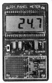
FIG. 4--THE TEMPERATURE-SENSING transistor can be located on the PC board,
but leads must be attached for calibration.
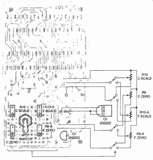
FIG. 5--THE CIRCUIT CAN BE MODIFIED as shown here to display part of the Fahrenheit
scale in addition to the Celsius scale. Alternative 2N2222 transistors are
installed as shown.
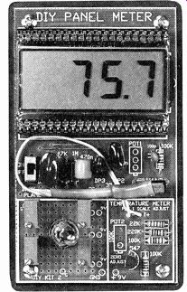
FIG. 6--MODIFIED THERMOMETER can display the full Celsius range and Fahrenheit
from about 60 to about 80°.
Cut a scrap of tinned lead wire to form jumper "J," insert and solder it. If you buy the digital thermometer kit, a case is included. The PC board fits securely in the top of the case to form a cover. Therefore, the in side the case provides enough space for the 9-volt battery. Solder the battery clip leads to the solder side of the board at the points shown in Fig. 2.
Refer to Fig. 3 and short-circuit Q1's base lead to its collector lead near the body of the transistor by bending them together and soldering them. Slip short lengths of heat shrinkable tubing over each input end of a two-conductor cable. Solder the two shorted transistor leads to the positive sensor input wire and the emitter lead to the negative input wire.
Slip a short length of heat-shrinkable tubing on both leads and pull it over the end of the transistor to form an outer protective jacket, as shown in Fig. 3. Heat the tubing so that it forms a tight shrink fit around both the end of the transistor and the cable.
Standard insulated hookup wire leads are suitable for the temperature probe up to about 6 inches long. However, if the probe is to be mounted on leads longer than 6 inches, use thin shielded cable.
The temperature probe can also be mounted on the PC board directly with leads soldered to the " + " and "- " probe inputs. This arrangement will, however, make thermometer calibration more difficult. If you elect this option, temporarily at tach the probe to the board with leads for calibration and mount it permanently to the board afterward. Figure 4 shows the completed digital thermometer.
Modifying the meter
As mentioned earlier, a small area on the PC board is set aside to accommodate components for experiments. We added two more potentiometers and a 4PDT switch to the circuit so the digital thermometer could be calibrated in Fahrenheit as well as Celsius degrees. Those modifications are shown in Fig. 5. The same figure also gives de tails for installing the alter native 2N2222 transistors, should you decide to substitute them.
Our tests showed that the meter's response is not perfectly linear for the Fahrenheit scale, and it is impossible to calibrate it at the boiling point of water because 212° cannot be displayed on the 3 1/2-digit display.
However, the response was linear enough for the display to give an accurate Fahrenheit reading from about 60 to 80°, the range in which most temperature readings are likely to be taken.
Calibrating the meter
Carefully inspect the circuit board for soldering errors and correct them before proceeding.
If the board passes visual inspection, connect a 9-volt battery to it and switch on power.
The display will either indicate a "1" or some other reading. If the display shows a "1," adjust potentiometers R9 and R10 to obtain a reading other than a "1." Fill a container with ice cubes and add a small amount of water. 'Rim on the digital thermometer and submerge its temperature probe in the ice water, holding it in close contact with an ice cube. Wait until the display stabilizes and then adjust ZERO control potentiometer R9 until the display reads 00.0.
Boil water in a kettle and care fully hold the probe over the kettle spout in the steam with tongs to prevent accidentally scalding yourself. When the display reading stabilizes, adjust SCALE control potentiometer R10 until the display reads 100.
If you have access to a digital multimeter with a temperature probe that is known to be calibrated, compare readings and adjust trimmers R9 and R10 more precisely.
If you added the Fahrenheit potentiometers, as shown in Fig. 5, calibrate the Fahrenheit scale next, bearing in mind the limitations discussed earlier. It is recommended that the temperature of ice water (32°F) and 80°F water be the test points.
The temperature of the hot water can be determined accurately with a standard laboratory mercury thermometer, but a high-quality, liquid-filled confectioner's thermometer will also give satisfactory results.
Measuring temperature
Observe common sense pre cautions when measuring temperature with your digital thermometer. If the transistor/ sensor is held near an open flame or heating coil it will be damaged or destroyed.
If you put the digital thermometer in a protective case to protect it from dust, rain, and salt spray, it will work reliably out of doors, in boats, or even on camping trips.
Keep the digital thermometer's temperature measurement limits in mind. The Harris ICL7106CPL has a rated temperature range of 0 and 70° Celsius.
adapted from: Electronics Now--Electronics Experimenter's Handbook 1996