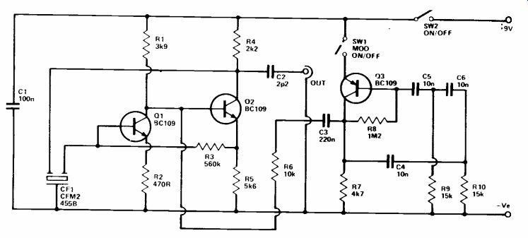
I.F. Alignment Oscillator
This simple piece of test equipment can be very helpful when aligning or realigning an AM superhet receiver. It provides an output at 455kHz, which can be modulated by an audio tone if the set is being adjusted for maximum AF output.
The circuit consists of two oscillator, Q1 and Q2 being used in the one which generates the 455kHz signal and Q3 in the one which provides the modulation signal.
Q1,2 are connected in a straightforward two stage, direct coupled, common emitter configuration. However, neither of the emitter resistors are bypassed in this case as only a low voltage gain is required. The input and output are in phase and positive feedback between the two is provided by ceramic filter CF1 (available from Ambit International). A significant amount of feedback is only provided at the 455kHz operating frequency of the filter and so the circuit oscillates at this frequency.
A ceramic filter gives good frequency stability, requires no adjustment in order to produce the correct frequency and is cheaper than using a crystal. C2 provides DC blocking at the output, al though it should normally only be necessary to connect the "hot" output to the receiver, no chassis connection being necessary.
A straightforward phase shift oscillator is used to provide the modulation signal and the specified C-R values give an operating frequency of about 500Hz. C3 and R6 couple this signal to the base of Q2 where it amplitude modulates the 455kHz signal. SW7 can be used to cut the supply to Q3 and thus remove the modulation.
+++++++++++++++++
Crystal Set
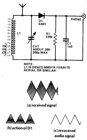
The most simple form of radio for receiving broadcast stations is the crystal set, or more precisely, a modern equivalent using a semiconductor diode to provide detection. This simple set covers the normal medium wave broad cast band, has an output for a crystal earpiece and, in most areas, should give reception of Radios 1, 2 and 3 at reasonable volume (plus any local radio stations where these are in operation on the medium waveband). It re quires no battery or other form of power source since energy de rived from the received transmission is used to drive the earpiece.
However, this does bring the disadvantage of needing an external longwire aerial to operate the set, as an ordinary ferrite aerial does not give sufficient pick up.
The tuned circuit is formed by L1 and CV1. This selects the desired transmission and rejects other stations. CV1 permits full coverage of the normal medium wave broadcast band to be achieved. In order to obtain good volume from the unit it is necessary to directly couple the aerial to the tuned circuit. For the same reason it is necessary to take the output to the detector direct from the tuned circuit. This inevitably gives the set rather poor selectivity, but it should still be adequate in this respect.
The form of modulation used on the medium wave band is AM (amplitude modulation). D1 half wave rectifies the RF signal to leave only the positive half cycles.
R1 and C1 are used to smooth the RF half cycles, but their time constant is too short to produce a steady DC output. Instead the output rises and falls in sympathy with the mean RF signal level, so that the original audio signal is recovered at the output and fed to the earpiece.
The only adjustment the finished unit requires is to slide the aerial coil (L1) along the ferrite rod to find a position that permits full coverage of the medium wave band. The coil is then taped or glued in this position. The smaller winding of the ferrite aerial is not required and is either removed or just ignored. The aerial should preferably be an outdoor type about 10m or so long, but a few meters of hook-up wire fixed around the walls of a room or in a loft should give reasonable results.
NOTE:
LI IS DENCO MIN5FR FERRITE AERIAL OR SIMILAR.
(a) received signal (b) action of D1 (c) recovered audio signal
++++++++++++
FET TRF Receiver
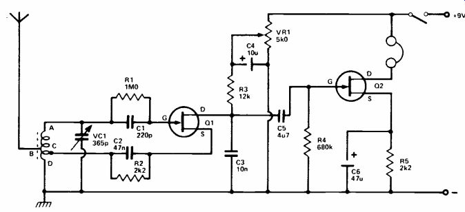
This circuit gives good headphone reception and can be constructed as a miniature receiver with a short throw-out aerial or it can be used with reduced range by relying on the ferrite rod alone.
Q1 is the detector and regeneration is obtained by a tap from the tuning coil to the source. The use of regeneration greatly improves selectivity and sensitivity to weak signals. Potentiometer RV1 allows manual adjustment of the drain potential of Q1 and so acts as a regeneration control.
Audio output from Q1 is coupled to Q2 by C5. This FET is an audio amplifier, operating the headphones. A complete headset is preferable for general listening and phones of about 500 ohms DC resistance, or about 2k impedance, will give good results here. If a miniature earpiece is used, it should be a medium or high impedance magnetic unit. A crystal earpiece will require RC coupling.
The tuning inductor is fifty turns of 26swg wire, on a ferrite rod about 5 in x 3/8 in. If the turns are wound on a thin card sleeve which can be moved on the rod, this will allow adjustment of band cove rage. The winding begins at A; aerial tapping B is at about twenty five turns and D is the grounded end of the coil. The best position of the tapping C depends some what on the actual FET, on the battery voltage, and on whether or not the receiver is to be used with an external aerial wire. Should the tapping C be too near to end D no regeneration will be obtained or regeneration will be weak, even with RV1 rotated for maximum voltage. On the other hand, with too many turns between C and D, oscillation will begin with RV1 only slightly advanced. Best results are expected when regeneration begins smoothly with RV1 about halfway through its rotation. It was found that only one to two turns were required between C and D. The best method is to make C two turns from D then, if necessary, unwind half a turn or more at D.
When regeneration is obtained, a heterodyne will be heard if the receiver is tuned through a transmission. RV1 should then be turned back very slightly. Maximum sensitivity is achieved when Q1 is almost in oscillating condition. RV1 has to be set to suit the frequency tuned by VC1, so that final critical adjustment can be made. It is useless to regard RV1 as a gain control, and set it at maximum.
A metal case is suitable where an external aerial wire will be used. Where the ferrite rod only will be employed the box or case must be of plastic or other insulating material.
++++++++++++++++
Morse Practice Oscillator
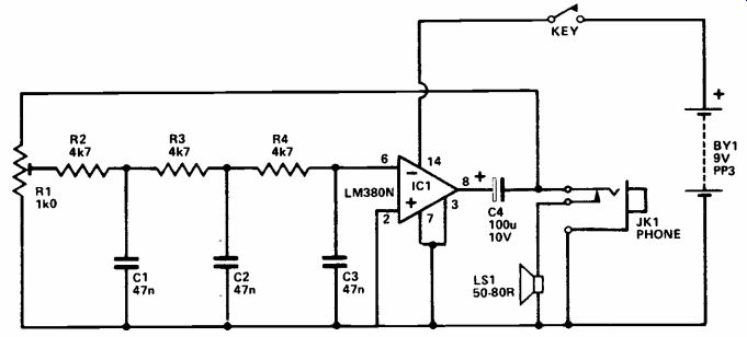
A Morse practice oscillator can be of considerable help when learning the Morse code. The simple unit described here has provision for an internal loudspeaker, and also has an output for a crystal earpiece, high impedance headphones, or a recorder.
The circuit is based on an audio power amplifier device (IC1) which is used in a phase shift oscillator circuit. Feedback is applied between the output and inverting (-) input of IC1 by way of a three section phase shift network. The three sections are formed by R2 -C1, R3 - C2, and R4 - C3, each of these sections providing 60 degrees of phase shift at a certain frequency. Thus, at this frequency there is a total phase shift of 180 degrees through the three sections. The circuit oscillates at approximately 1k5Hz with the specified values.
Ideally a circuit of this type should provide a sinewave output, as a pure tone is easy to listen to for long periods and is the wave form produced by an actual CW (Morse) transmission when it is resolved by a receiver. This circuit will provide a reasonably pure sinewave if the gain of the amplifier just slightly more than compensates for losses through the feed back circuit. This is achieved by adjusting R1 to give the appropriate loss level through the feedback path. In practice it is backed off close--close to the point where oscillation ceases, due to a lack of feed back.
The output signal is fed to the loudspeaker via C4 and a break contact on the output socket. The latter automatically cuts of the speaker when a plug is inserted into the socket. The unit provides an output power of about 100 mW rms, and has a current consumption of approximately 20mA with the key down.
+++++++++++++++
Crystal Calibrator
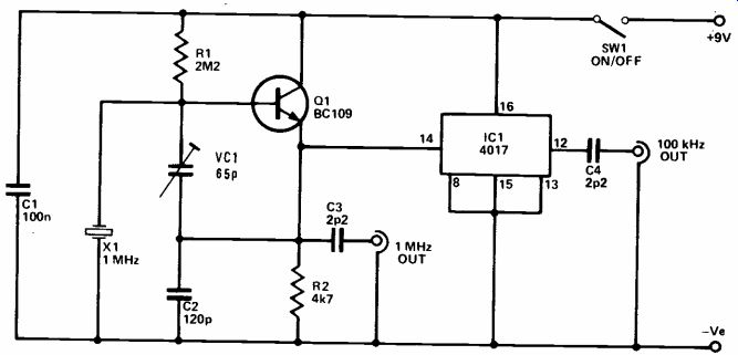
A problem with home-constructed short wave receivers is that of providing an accurately calibrated tuning dial. A crystal calibrator solves this problem.
The calibrator circuit shown here has fundamental outputs at 100kHz and 1MHz. However, it does not merely provide calibration signals at these frequencies, but also at harmonics of these frequencies. The 1MHz output therefore provides calibration signals at 2MHz, 3MHz, 4MHz, etc., while the 100kHz output provides signals at 200kHz, 300kHz, 400kHz, etc. These additional frequencies are produced because the circuit is designed to give an output signal that is virtually a squarewave. This gives a signal rich in harmonics at frequencies that are readily detectable up to 30MHz (the upper limit of the short wave spectrum) on any reasonably sensitive receiver.
Q1 is used in a simple 1MHz crystal oscillator, and it operates in the emitter follower mode. VC1 and C2 effectively form a tap on the crystal which acts as a parallel tuned circuit. The output of Q1 is coupled into this tapping, and this gives the positive feedback path needed to produce oscillation. The circuit oscillates at the resonant frequency of the crystal since there is only an efficient feedback path at this frequency, sufficient to produce strong oscillation and an output rich in harmonics. A crystal is used rather than an ordinary L-C tuned circuit as a crystal gives better accuracy and stability. The 100kHz output is obtained by feeding the 1MHz- signal to a CMOS 4017 divide by ten circuit.
VC1 must be adjusted to give optimum accuracy and this is easily achieved by connecting a short lead to the 100kHz output and placing it near a radio tuned to the BBC LW 200kHz transmission. This will produce a low frequency beat note (heard as a cyclic rise and fall in the volume of the station), and VC1 is simply adjusted for the lowest attainable beat rate. A beat rate of under one per second should be easily obtained.
++++++++++++++++
10 to 30MHz Preselector
Many older or less expensive SW receivers give a relatively poor level of performance on the high frequency bands. One way of improving the performance is to add a preselector at the input.
A preselector is a tuned RF amplifier which boosts the aerial signal before it is fed to the receiver.' Apart from giving improved sensitivity, the decreased RF bandwidth helps to attenuate any spurious responses by the receiver.
The aerial signal is taken to the low impedance primary winding of T1. VC1 can be used to resonate the tuned circuit at any frequency between about 10 and 30MHz; in practice, VC1 is simply adjusted to peak received signals, and is the tuning control of the unit.
Q1 is a JFET which is used in the common source mode, and has R1 and C1 as its source bias resistor and bypass capacitor respectively.
It directly drives the input of Q2, which is an ordinary bipolar device used in the common base mode. This has R2 as its collector load, R3 and R4 to provide base biasing, and C2 as the base decoupling capacitor. This two stage amplifier is a form of "cascode" circuit, and gives good performance at the fairly high frequencies involved here. The voltage gain of the circuit is well over 20dB. C3 provides DC blocking at the output of the unit.
Construction of the unit is not critical, but try to keep all the wiring reasonably short. As supplied, the core of T1 is fully screwed into the former, and in order to obtain the correct frequency coverage the core must be unscrewed so that approximately 10mm of metal screw thread protrudes from the top of the coil. T1 can be mounted in a B9A valveholder, incidentally. The twin lead connecting the output of the preselector to the aerial and earth sockets of the receiver should be reasonably short to minimize losses.
+++++++++++++++
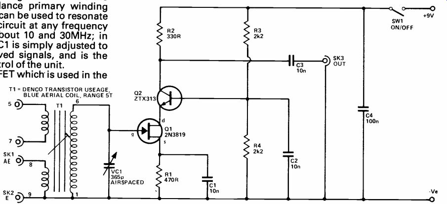
Medium Frequency Amplifier
This circuit is primarily intended for use over the 1.7MHz to 30MHz range and will be found to provide considerable gain. RF amplifiers of this kind are generally used to improve long distance short wave reception, to increase volume, and to reduce second channel interference on the higher frequencies.
To avoid winding coils and permit easy band changing, Denco ( Clacton) miniature plug-in coils may be used; these are the "Blue" (Aerial) ranges. The most useful coils will be Range 3, 1.67 5.3MHz, or 580 to 194 meters; Range 4, 5-15MHz, or 60 to 20 meters; and Range 5, 10.5-31.
5MHz, or 28 to 9.5 meters. Exact coverage depends on the setting of the adjustable cores, and will also be modified if VC1 is of different value. The coils are inserted in a B9A type holder. If only a single range is wanted, the coil can be mounted by its threaded end, and leads are then soldered directly to the pins.
RV1 is an adjustable aerial input control, as overloading may easily arise with strong signals. R1 and R2 provide the voltage for gate 2, and If3 is for source bias.
The drain circuit is arranged for capacitive coupling by C4 to the aerial socket of the receiver. This lead should not be unnecessarily long, as this may cause losses, as well as picking up signals which cause second channel interference. If the lead is screened, it must be no longer than necessary.
A 2.6mH short wave sectionalized radio frequency choke will be satisfactory for the frequencies mentioned.
Construction is best in a metal case, which can have a hinged lid if plug-in coils are to be fitted. No ganging difficulties can arise with VC1, which is adjusted for best volume.
Second channel interference is caused by signals which are 2 x IF frequency from the wanted signals. With a 470kHz intermediate frequency, these offending signals will be 940kHz from the wanted transmission. As a result, interference from this cause is unlikely at low frequencies, but very probable at high frequencies. Such second channel interference is considerably reduced, or completely avoided, by using a tuned RF stage of this kind; actual results depend on the receiver IF, and frequencies tuned.
A 9 V supply is adequate and may be drawn from the receiver if convenient; only 2mA to 3mA or will be wanted. The MEM618, 40602, and 40673 will be found satisfactory here.
++++++++++++++++
Two-Transistor Radio
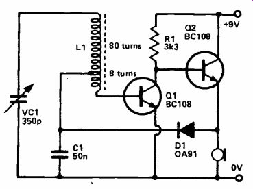
Although transistors are cheap, this was certainly not true some years ago, and transistors were made to work at maximum efficiency. A common technique in simple radio circuits was to use a reflex circuit; that is, one transistor amplified both at RF and AF.
The circuit shown uses very few components yet the operation is surprisingly complex. The coil L1 is made from 88 turns of enameled copper wire, 32 swg for example, on a 5/16in ferrite rod about 4in long with a tap at 8 turns. The tuned circuit is made up from VC1, the 80 turns of L1 and C1. The latter has practically no effect upon the circuit as it is a very high value for RF purposes.
The RF signals picked up in circuit appear at a very high impedance which does not connect well to a regular transistor amplifier, but the 8 turns act as an auto transformer giving a good match to the base of Q1. This transistor amplifies the RF which is fed to Q2, acting as an emitter follower.
The RF appears at the emitter of Q2 but the high impedance magnetic earpiece acts as an RF choke so the signal is passed through D1 and is detected by it and smoothed by C1. The signal is now at audio and it is connected to the base of Q1 via the 8 turns and is again amplified but this time it drives the earpiece; some audio is fed back but this acts as negative feedback. The base bias for Q1 is also supplied via the diode.
Most general purpose small signal transistors such as a BC 108 will work well in this circuit. R1 is worth experimenting with to obtain the best possible performance.
Note that most earpieces are 8 ohm types and will barely work in this circuit, high impedance types are less common than they used to be but are available - the impedance should not be less than 250 ohms. The value of VC1 is not very critical - almost all of the transistor type tuning capacitors will work.
+++++++++++++++++++++
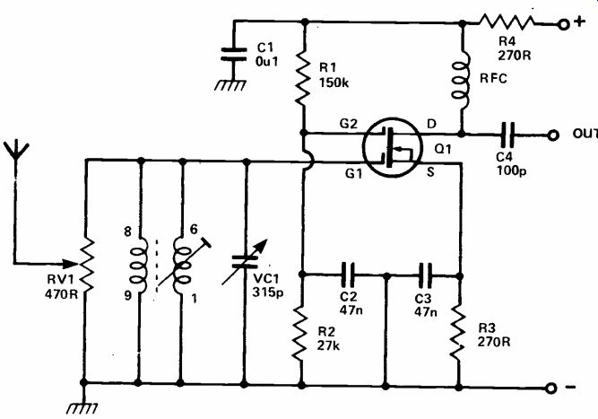
Simple SW Radio
This simple SW set tunes from about 5 to 17MHz, covering the 19, 25, 31, 39 and 49 meter broadcast bands. It can be used with an external aerial and earth (which connect to SK1 and SK2 respectively), but it provides reception of a large number of stations using a short telescopic aerial.
VC1 is the tuning control, and forms the tuned circuit together with the main winding of T1. Signals from a long wire aerial are coupled to the tuned circuit via a small coupling winding on T1, but if a telescopic aerial is used it is necessary to directly couple it to the tuned circuit. Signals at the frequency selected by the tuned circuit are fed into the gate of Q1 which is used as a common source RF amplifier/regenerative detector. The process of regeneration merely entails sending some of the output from Q1 drain back to the input of the circuit so that it is amplified for a second time.
This achieved by using a third winding on T1, with C1 providing DC blocking and RV1 controlling the amount of regeneration.
There are several reasons for using regeneration; the obvious advantage is that it gives increased gain and sensitivity. A less obvious one is that it increases the detection efficiency of the circuit. This type of detector relies upon the fact that it will amplify one set of half cycles more than the other set, giving a crude form of rectification. Thus, by adding an RF filter (R3 and C3) at the output of the amplifier, the RF signal is removed to leave the detected AF signal. Regeneration increases the inequality between the levels of amplification received by the two sets of half cycles, giving improved detection efficiency. Re generation also produces improved selectivity, enabling the set to pick out just one station at a time from the crowded SW broad cast bands.
The audio output from the detector is considerably amplified by a common emitter stage based on Q2 before being fed to a crystal earphone or a pair of high impedance headphones. Current consumption of the set is about 2mA. Construction would not be difficult, but all the RF wiring should be kept reasonable short and direct. T1 can be mounted in a B9A valveholder by the built-in screw-thread and nut.
++++++++++++++++
27 MHz Radio Control Monitor
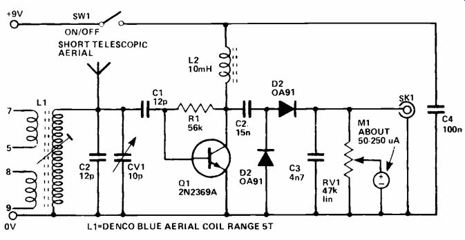
A radio control monitor such as that described here is invaluable when setting up a radio control transmitter. This circuit has good sensitivity and it is unnecessary to have the monitor in close proximity to the transmitter in order to obtain a signal of adequate strengths even when it is used with a low power transmitter.
The signal picked up by the telescopic aerial is coupled directly into the tuned circuit. The core of L1 is adjusted so that CV1 is able to tune the monitor to any frequency within the 27MHz band.
The setting of this core is not too critical, since the unit covers somewhat more than the entire band.
Q1 is used as a common emitter amplifier with L2 as its collector load and R1 to provide base biasing. C1 couples the signal in the tuned circuit to the input of the amplifier. The value of C1 is chosen to give optimum signal transfer. The high impedance signal in the tuned circuit is matched to the low input impedance of Q1 by a sort of capacitive divider action (the input capacitance of Q1 forming the other section of the capacitive divider).
C2 couples the output of Q1 to a straightforward rectifier and smoothing circuit. This produces a positive voltage which is roughly proportional to the strength of the received signal. This voltage is used to drive M1, which gives a comparative indication of received signal strengths. An inexpensive meter is perfectly suitable for use in the unit due to the arbitrary scaling. RV1 can be used to reduce the sensitivity of the unit, if necessary. The modulation signal of the transmitter (if it is an AM type) can be monitored using a crystal ear phone connected to SK1.
+++++++++++++++++++
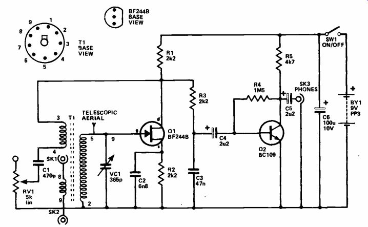
Simple M.W. Radio
This simple radio gives many hours of use from a PP3 battery, and will give good volume from a crystal earphone when tuned to all but the weakest of MW transmissions.
L1 is the tuned winding of the ferrite aerial, and VC1 is the tuning capacitor. The signal picked -up and selected by the aerial is coupled via low impedance winding L2 to a conventional common emitter amplifier stage based on Q1. Some of the output from Q1's collector is coupled back to the ferrite aerial by R1 and C1. R1 controls the amount of feedback, or regeneration as it is normally known in this application. One purpose of the regeneration is to produce increased amplification, and thus give improved sensitivity. It also improves the ability of the set to select just one of several closely spaced transmissions. This is very important, since the selectivity of the set is provided by a single tuned circuit, and performance would be very poor in this respect without the use of regeneration.
Most of the output from Q1 is fed to a simple diode detector circuit which uses D1, D2, C4 and R4.
This halfwave rectifies the RF signal and smoothes the remaining RF half cycles to leave the audio signal. This is then fed to a low noise audio stage which uses IC1 in the inverting mode. IC1 is a low noise BIFET operational amplifier; its closed loop voltage gain is set by the ratio of R5 to R8 at about 550. The current consumption of the set is only about 2mA.
The aerial coil must be positioned on the rod so that the full MW band can be received. This is a matter of trial and error. The coil is then glued or taped in place. R1 is adjusted for the lowest value that does not cause the circuit to oscillate at any setting of VC1 (oscillation causes a tone to accompany the received station). If regeneration cannot be obtained, re verse the connections to L2. Keep the wiring to the "hot" ends of VC1 and L1 well away from the wiring to Q1 collector or uncontrollable regeneration may result.
++++++++++++++++++
144 MHz Converter
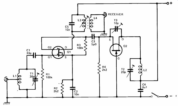
The reception of 2 meter signals is generally possible using a converter and standard short wave receiver. With such an arrangement the 144MHz or other VHF signal is changed in frequency so that the converter output falls within the tuning range of the receiver.
A converter of this type often uses an RF amplifier and a low frequency crystal controlled oscillator followed by frequency multipliers. This allows high sensitivity and excellent frequency stability but is relatively complicated and expensive item. It is possible to use a much simpler circuit.
L1 is broadly tuned to the wanted frequency band by T1 and signal input is to gate 1 of Q1. Q2 is the local oscillator with the operating frequency determined by L2 and T2. Oscillator injection is via C3 to gate 2 of Q1. The frequency of the output from drain of Q1 is the difference tween G1 and G2 frequencies.
Thus if the signal at G1 is 144MHz, and Q2 is tuned to oscillate at 116MHz, output will be at 28MHz.
Therefore 144-146MHz can be covered by tuning the receiver from 28MHz to 30MHz. L3 is broadly tuned to this band, and L4 couples the signal to the receiver.
The oscillator can actually be tuned above or below the aerial circuit frequency of the converter, Radio as it is the difference between converter signal input and oscillator frequencies which determines the converter output frequency. It is also possible to choose other reception and output frequencies, provided L1, L2 and L3 are chosen to suit.
L1 and L2 are wound in the same way, except that L1 is tapped one turn from its grounded end. Each coil has five turns of 18 swg wire, self supporting, formed by winding the turns on an object 7mm in diameter. Space turns so that each coil is 1/2in or about 12mm long.
L3 is fifteen turns of 26swg enameled wire, side by side on a 7mm former with adjustable core.
L4 is four turns, overwound on the earthed (positive line) end of L3.
Layout should allow very short connections in the VHF circuits. A co -axial aerial socket is fitted near L1. A screened coaxial lead is preferred from L4 to the receiver to avoid unnecessary pick-up of signals in the 28-30MHz range. The converter will operate from 9-12V.
L3 should first be peaked at about 29MHz. If a signal generator is available, couple this to Q1 drain by placing the output lead near the drain circuit. Tune generator and receiver to 29MHz, and adjust the core of L3 for best results. Otherwise, couple an aerial by means of a small capacitor to the drain circuit, and tune in some signal in the 28-30MHz range.
It is now necessary to tune L1 to about 145MHz, and L2 to 116MHz, or 174MHz. If an absorption frequency indicator is available, this will permit an approximate setting of T2. A dip oscillator will also allow T1 to be adjusted. Subsequently adjust T2 to bring the wanted signals in at the required frequencies and peak these for best volume with T1, then check the setting of L3 core.
The converter is best assembled in a small aluminum box, completely closed, which can be placed behind the receiver. Note that if Q2 is not oscillating, no reception is possible through the converter. Q2 should be a VHF FET, such as the BF244, MPF102 or similar and if necessary T3 may be adjusted to secure oscillation. The 40602, 40673, or similar VHF types will be satisfactory for Q1. If needed, frequencies can be brought within the swing of T1 and T2 by stretching or compressing L1 or L2.
The aerial may be about 381/2in long, constructed as a simple self supporting or wire dipole, with a feeder descending to the converter. Amateur activity is most likely to be greater at week ends, and in many areas a whip or very short wire aerial will provide local reception.
+++++++++++++++
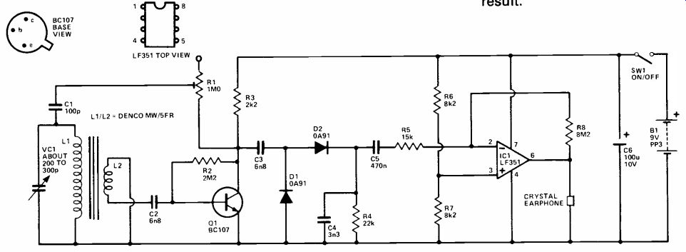
Radio 4 Tuner
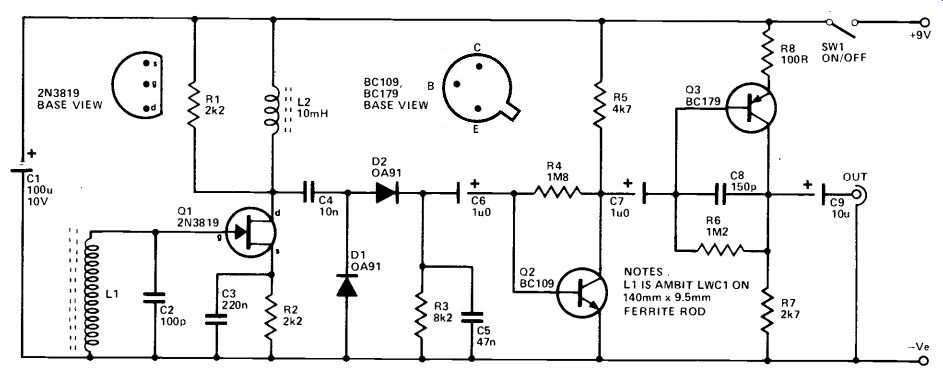
This tuner is designed for use with a tuner/amplifier which does not have long wave coverage and is therefore to receive BBC Radio 4.
However, it can also be used as a personal receiver for reception of Radio 4 if the output is fed to a crystal earphone or a pair of high impedance magnetic headphones.
Q1 is used as a JFET common source amplifier and its gate terminal is fed direct from the ferrite aerial (L1). This is quite acceptable since a JFET has an extremely high input impedance and will not place a significant degree of loading on the aerial. L1 is used to bias the gate of Q1 to the negative supply rail. C2 brings the ferrite aerial to resonance at approximately the Radio 4 frequency of 200kHz, and L1 is simply slid along the ferrite rod to tune the unit to the correct frequency. L2 forms the main source load for 01, but it was found to be necessary to damp this using R1 in order to prevent instability.
The amplified RF output from Q1 is fed by C4 to a straight for ward AM detector circuit, D1, D2, R3 and C5. The demodulated AF signal is then coupled by C6 to a high gain, low noise, common emitter amplifier based on Q2.
This considerably boosts the signal, but it is still at an inadequate level to drive many amplifiers. A second common emitter stage using Q3 is therefore used to further boost the signal, and this gives an output amplitude of several hundred millivolts RMS. The full gain of Q3 is not required, and R6 is used to provide local negative feedback which produces the required reduction in gain. C8 rolls off the high frequency response; this aids stability and improves the signal to noise ratio of the unit.
The tuner only has one control, on/off switch SW1. The current consumption of the unit is about 2.5mA. When the correct position on the ferrite rod has been located, it should be firmly taped or glued in position.
++++++++++++++++++++++++
Bedside Radio
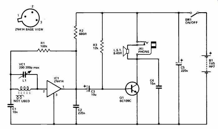
This very simple MW radio provides low but adequate loud speaker volume for use as a bed side set, and also has provision for a low impedance magnetic ear phone. The radio frequency circuitry is based on a ZN414 IC which provides considerable amplification for the signals picked up in ferrite aerial L1. VC1 is the tuning capacitor and R1 is a bias resistor for the ZN414. C1 provides an RF path to earth for the "cold" end of L1. The ZN414 has a transistor detector stage at the output, but this requires discrete load resistor R2 and RF filter capacitor C2 in order to give an audio output.
When strong signals are received there is a slight drop in the voltage at the output of IC1, effectively reducing the supply voltage fed to the device and giving a fall in gain. This produces a crude but reasonably effective form of automatic gain control (AGC) which reduces the possibility of overloading and gives a more consistent audio output level when tuning to stations of differing signal strengths.
The output stage is a simple common emitter class A type based on Q1. Interstage coupling is provided by C3, and R3 is the base bias resistor. The speaker or earphone form the collector load for Q1; JK1 is a normal 3.5mm jack having a single break contact which is used to automatically mute the speaker when the earphone is plugged in. Ideally the speaker should have an impedance of about 15 to 26 ohms, but any unit having an impedance in the range 8 to 40 ohms can used. C4 filters out any RF signal that breaks through to the output and which might cause instability.
The layout of the unit is not too critical, but C2 should be mounted physically close to IC1. As with any set having a ferrite aerial and internal speaker, the two should not be positioned very close to one another as this could cause instability. A metallic case cannot be used as it would shield the aerial and prevent any significant signal pick up. Large metallic components positioned right along side the aerial can have a similar effect.
+++++++++++++++++
Short Wave Converter
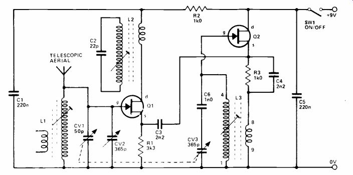
This SW converter tunes over 5 to 15MHz approximately and also enables an ordinary MW broadcast receiver to pick up stations operating on the 19, 25, 31, 41 and 49m broadcast bands.
Signals picked up by the telescopic aerial are directly coupled into the aerial tuned circuit as these signals will be quite weak, necessitating a tight coupling.
CV2 is the main tuning capacitor and CV1 is the aerial trimmer control. The signals selected by the tuned circuit are coupled directly into the gate of mixer transistor Q1, no coupling winding being needed here due to the use of a JFET transistor with a very high input impedance. The drain load for Q1 is a MW ferrite aerial, but it is used in reverse in this application, to radiate the 1.6MHz output of the converter. This is picked up by the MW radio, which is placed near the converter and tuned to a quiet spot on the band in the vicinity of 1.6MHz. The position of the coil on the ferrite aerial is adjusted to resonate L2 at the appropriate frequency and effect optimum signal transfer.
The oscillator uses JFET device Q2 in the source follower mode, with positive feedback provided by L3. At the resonant frequency of L3 there is sufficient feedback to cause oscillation and CV3 tunes the oscillator over a frequency range which is 1.6MHz higher than the range of the aerial tuned circuit, so that the required difference frequency of 1.6MHz is produced at the output. C6 is a padder capacitor which gives reasonably good tracking between the aerial and oscillator circuits.
Perfect tracking is not required since CV1 can be used to keep the unit peaked for optimum results.
C3 is used to couple the output from the oscillator to the input of the mixer stage. The circuit has a current consumption of only 4mA.
(adapted from: Electronics Digest (Vol. 2 No. 3--WINTER 1981))
NEXT: Test Gear